1
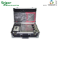
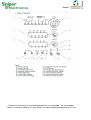
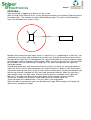
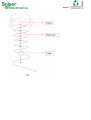
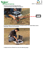
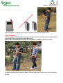
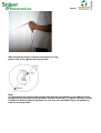
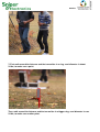
Member
INTRODUCTION:
Sniper Electronics System is an advanced Metal
Detector System utilizing advanced technology that is both an audio and
visual detector. This metal detector was first used in the field in 1984 and the
technology that it uses has proven to be (by far) the most successful.
This system was originally developed for professional archaeologists and treasure hunters and
has been used on many stations. With the development of faster and more complex processing
units and a reduction in the cost of materials, we were able to begin offering this breakthrough
technology to the general public at a much more affordable cost. Part of the success of this metal
detector system is that it does not look like a standard ‘metal detector’. Instead, it has the
appearance of a fine, well manufactured piece of scientific equipment that one might expect to
find at an archaeological site.
The SNIPER ELECTRONICS-UG050M is ‘custom built’ in a sturdy, hard side, padded case with two
locks. The
transmitter is case mounted and includes the ‘Standard Seven’ elements with selector switch.
The system includes an installed, rechargeable gel cell battery with charger, transmitting antenna,
receiving rods and receiver with belt clip, headphones and user manual all inserted into the
specially fitted case.
To obtain maximum performance, we urge you to take a few minutes to read this manual
carefully.
PARTS AND NAMES:
1. Carefully unpack and familiarize yourself with the components of your SNIPER ELECTRONICSUG050M
Remote Sensing Detector System. The components are:
• A black case with aluminum trim, a handle and two locks. This case contains the
transmitter unit and all other components. The transmitter is permanently mounted in the
case.
Member
Member
• Besides the transmitter, the remaining components are removable. The rechargeable
battery is already installed in this unit. Battery must be charged overnight prior to first use.
Member
It should not be recharged until LED’s indicating the elements begin to dim or there is no
longer interference on the AM radio when transmitter is turned on.
• Head Phones - one set of head phones. Plugged in the bottom right corner of Belt
Receiver
• Enhancer
Member
• The Belt Receiver - this is a gray box. It is labeled “SNIPER ELECTRONICS-UG050M ”. On
the face (front) is an ON/OFF/VOLUME knob. In the top left corner there is Enhancer, in
the right there is an LED (light). This light is on at any time the receiver is on. To the left of
the knob there are two jacks (plug receptacles). They are labeled Head Phones and Rods
respectively. There is a belt clip on the back of the box. This component takes
rechargeable batteries. The batteries are factory installed.
Enhancer
Plug Socket
Head Phones
Plug Socket
ON/ OFF/
VOLUME Knob
Plug Sockets of
Antenna
(Receiving) Rods
Jack of Charger
Member
• Antenna (Receiving) Rods - these are sealed copper cylinders, and black and red wires
that terminates with plugs, these plugs fit the black and red receptacles on the belt
receivers. Extending perpendicularly from each cylinder is a brass rod sheathed in copper
tubing. The copper tube slides forward to extend the rods.
• Battery Charger of Belt Receiver; AC/DC adapter, input AC 220V 50Hz, output DC 3.6V
450mA.
• Battery Charger of Transmitter. DO NOT reverse sequence. 1000mA, 240V.
Member
• Antenna (Sending) - the antenna is red and black rectangle, approximately 6.5” x 16”.
There is a black cord extending from the top of the antenna that terminates with two plugs,
one red and one black. The bottom of the antenna is red up to approximately 3.5” from the
bottom of the antenna on each upright of the antenna. The antenna is stored in the top of
the case.
• Mark Flag
• Keys of the Outer case and the On/Off Switch on the Transmitter.
2. Move toggle switch to the ON position to test lights. Transmitter may be tested by placing a
Member
small transistor radio, tuned to the lowest AM frequency, next to transmitter while it is on.
There should be interference on the radio if the transmitter is functioning. Turning the largest
knob on the transmitter will cause each light to light in sequence. The interference will change
tone when the different elements are selected.
3. After unpacking the antenna rods, and before you plug them into the Belt Receiver, you will
need to practice with them to ‘get the feel’ of them.
• Extend the rods approximately six inches.
• Take one rod in each hand.
• Hold hands about twelve inches apart.
• Start with the ends of the rods about five inches apart and tilted slightly downward about
two inches.
• RELAX
• Walk at a normal pace.
• Do not raise or swing rods.
• Practice walking with rods until you can walk without swinging them. Mastering the use of
the rods may take some practice, but is one of the key skills needed to effectively use your
system.
4. After you have mastered using the rods, attach the Belt Receiver to your belt in the center front
of your body. This is the optimum location for the receiver.
• Plug the antenna rods into the Belt Receiver.
• Test the rods as you did in step three. This is to make sure that there is no interference.
5. Now that the components have been tested and found functioning it is time to field test the
system. Field test system in an area as free of metal debris as possible.
6. To field test the system, place transmitter on the ground, plug the antenna into corresponding
receptacles (labeled output jacks). NEVER PLUG IN OR UNPLUG ANTENNA WHILE
TRANSMITTER IS ON. DOING THIS WILL CAUSE DAMAGE TO THE SYSTEM AND
SERIOUS INJURY TO THE OPERATOR. Dig a small trench, approximately 3.5” deep, in
front of the transmitter, in which to bury the antenna up to the black lines. Set the selector to
the desired element. Turn on transmitter. Turn the horizontal and vertical knobs
counter-clockwise as far as they will turn. Then, turn them clockwise just until the LED above
the corresponding knob starts to brighten. Not all the way to the right. (This sets the
transmitter to the ground conditions where you are working.) After three to five minutes, while
standing approximately 25’ from the transmitter, plug in receiving rods and the head phones
into the receiver and place head phones on head. Turn on receiver set to half volume, there
should be no sound. Walk slowly toward the transmitter. When you hear the same noise
that you heard on the radio as you were testing the transmitter, note your distance from the
transmitter. Back up approximately five feet, example, if you walked to within 15 feet of the
transmitter, back up until you are approximately 20 feet from transmitter. Using 20 feet as an
example. Using the rods, as practiced, walk a circle around the transmitter, staying
approximately 20 feet from the transmitter. If the area is clear of target element, the rods
should not cross.
7. To practice using the system bury a test object, approximately the weight of several coins or
pieces of jewellery, about 50 feet from the transmitter.
8. Repeat Step 6. As you approach the line between the antenna and your test target, you will
Member
begin to hear a frequency in the headset. When you are on the line between the antenna and
the test target the sound will be the loudest. Now the rods should cross when the line
between the test target and the transmitter is crossed. (Remember the line will form between
the antenna in the ground and the target - not the transmitter and the target.) As you pass the
line, the volume will be reduced to nothing and the rods will uncross. Mark where the sound
was the loudest and the rods crossed. Now move another ten feet from the transmitter (if you
were 20 feet away from the transmitter, move out to 30 feet). Repeat the process, again
marking where the noise was the loudest and the rods crossed. By drawing a straight line
from the transmitter through the two places you marked you will have your X Axis. Shut off
belt receiver and transmitter. Wait 15 minutes, then move the transmitter and antenna to a
new location, repeat the process. Remember to bury the antenna. The line that is developed
this time will be your Y Axis. Where the X Axis and Y Axis intersect will be your target.
9. After Steps 4 through 8 have been mastered it is time to try to locate unknown targets.
10. Select search site. It is suggested that you bury a test target at the search site to test the
system and conditions. Repeat Steps 6 through 8. After successfully completing Step 8,
remove test target and turn off transmitter. Wait about fifteen minutes before beginning
actual search. Repeat Steps 6 through 8 while searching for desired target element
NOTES:
1. Test each search site at least twice. Locate the transmitter at least 50 feet from the first
location for the second test. This will eliminate the possibility that a null reading was caused
by the transmitter being placed directly on or within a few feet of the target.
2. Remember that you should not have any electronic devices or metal objects attached to your
body, (especially cellular phones and pagers).
3. The line is developed from the antenna in the ground not from the case and/or transmitter.
4. Turn off transmitter when changing elements or when changing position of transmitter for
triangulation, and wait at least fifteen (15) minutes before turning it back on. (This is to allow
the first line to fade before developing the intersecting line.)
5. Do not add any metal or other test objects to the area being tested while the transmitter is
turned on.
6. Under certain conditions, the line formed between the transmitter and the target may function
as an antenna. Therefore you may hear AM radio transmissions hear the transmissions when you
are on the line.
Member
PROPOSAL :
Now, we provide a suggestion of how to use the system.
After finishing all the field test of this system, placing transmitter on the ground. Plug the antenna
into output jacks. This antenna can cover 360° detecting range. The most sensitive detecting
area is as the dotted lines shown in Fig1.
antenna
Between the antenna and your target, there is a signal line (it is a suppositional, virtual line). You
should carry the receiver rods and attach the receiver unit, and walk around the antenna to find
one point of the signal line. As you approach the signal line between the antenna and your target,
you will begin to hear a frequency in the headset. When you are on the signal line, the sound will
be the loudest, and the receiving rods should cross. Pls. note, every point on the signal line
should be marked.
According to above way, walk around the Antenna and the Transmitter for seeking the point of
signal line. At the 1st time, distance between you and the Antenna is about 5~10m. And make a
mark when receiving rods cross. At the 2nd time, choose another place, the distance between you
and the the Antenna should be 20~25m. then walk around the Antenna. When the rods cross,
make another mark. See Fig2. Note: all marks and the Antenna should be in one signal line.
Move the Transmitter and Antenna to another place. Walk around the Antenna and the
Transmitter as above way to confirm marks and confirm the second signal line.
These two signal line should be cross. The coss point is the target place.
When the rods are not corssed, you have deviated your target. When you pass the target, the
rods will turn and point the target.
Member
Member
Followed are the Detailed Operation Tips:
1. put half of Antenna (Sending) in the ground.
antenna
2. Connect Antenna with the machine, and put the Keys in the On/Off Switch on the
Transmitter. Turn on the Transmitter.
3 .Adjust the Seven Channels to select the detecting target.
Member
Turn Horizontal Distance Selector and Vertical Depth Selector to select the
detecting range and detecting depth.
4. Turn on the Belt Receiver, and connected with the Antenna (Receiving) Rods. You can set
the
Belt Receiver on your belt. Please refer to the below picture:
Member
Note: All above is ready, please wait for 15 minutes, before starting to detect.
How to detect ?
5. All the above is Ok and starts to detect. One person takes the Belt Receiver and Antenna
(Receiving) Rods, other person takes Mark Flag.
Move slowly around the Antenna and the transmitter, it is better 2 feet per second.
And pay attention how to take the Antenna (Receiving) Rods. Please refer to the following
picture.
Member
Walk around the Antenna and the transmitter in a ring.
please refer to the right picture how to walk.
Note:
(1). Keep taking the Antenna (Receiving) Rods position and parallel as the above pictures.
(2). Must move slowly around the Antenna and the transmitter, it is better 2 feet per second.
6. When the Antenna (Receiving) Rods are crossed, stick one Mark Flag in the ground to
mark the cross position.
Member
7. First walk around the Antenna and the transmitter in a ring, semi diameter is about
5‐‐10m, to make sure a point.
Then, walk around the Antenna and the transmitter in a bigger ring, semi diameter is over
5‐‐10m, to make sure another point.
Member
And the Antenna and the transmitter and the two points are in one line, refer to the below
picture:
8. Above is first step detecting, and change the Antenna and the transmitter position, and
detect again following the above detecting method, to make sure another line.
The cross of the two lines is the position of the gold. Please refer to the below picture.
Member
ADDITIONAL INSTRUCTIONS :The following are step-by-step directions on the use of the antenna and system. Consult
diagram to help you with these directions.
Insert the antenna. While the antenna covers an area 360 around it, the best useable area is that
area radiating in front of and to 60° from each side of the antenna. This area is enclosed within
the dashed lines of the diagram.
After you have established this sector; move to one of the edge of one of the angles,
approximately 15’ from the antenna. You can be as close as 10’ to a maximum of 18’. You don’t
need to go any further from the antenna than this to determine whether there is a possible target
in the area covered between the two angles. Set the headset volume to the lowest setting that
you can still hear. Now begin walking the arc between the two angles. You will hear a gradual
increase in the tone as you approach the center of the arc. This tone will gradually decrease as
you pass the arc and move toward the other angle. If you cross a target line, as you walk the arc,
you will experience a sharp increase in tone that will immediately decrease as you pass the line.
If you experience this, the rods should also cross. Walk over that area again but this time place
a flag where the sharp tone begins and another where it ends. Continue to the far edge of the arc.
Now walk back across the arc. If you again experience the sharp increase in the tone place a flag
at the beginning and end as you did before.
The target line is in the center between the flags. Take a compass reading of that line.
Member
Now move the antenna to another location on the site and repeat the procedure above. The
target is where the lines cross.