1
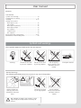
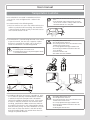
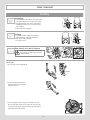
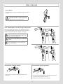
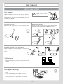
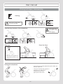
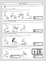
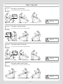
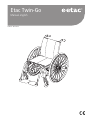
Etac Twin-Go
Manual english
75225C 2014-12-22
Contents
1. General – introduction
7. Settings back support
Settings back support height..............................................29
Settings back support angle...............................................29
Settings back support upholstery.......................................29
Intended use........................................................................3
Tests and Guarantees...........................................................3
2. Description
...........................................................................................4
8. Readjustments
Brake, adjustment..............................................................30
Adjusting the brake block .................................................31
Anti-tips.............................................................................31
Adjusting the centre of balance.........................................31
Handrims...........................................................................32
Adjusting the distance of the handrim...............................32
3. The chairs possibilities
....................................................................................... 5-6
4. Accessories
....................................................................................... 7-8
5. Settings
Rear seat height...................................................................9
Adjusting rear seat height by changing rear wheel position ...
..................................................................................... 9-10
Rear seat height table........................................................11
Drum brake.......................................................................12
9. Accessories - adjusting, handling
Seat cushion and comfort wedge.......................................33
Arm support, detachable, height adjustable.......................33
Positioning belt..................................................................34
Head support ....................................................................34
User manual
................................................................................... 13-24
Symbols and warnings.......................................................14
Transportation in vehicles...................................................15
Handling...................................................................... 16-17
Seat comfort................................................................ 18-19
Driving technique, maneuvering................................... 20-23
Maintenance & Fault-finding chart.....................................24
10. Service and maintenance
Upholstery.........................................................................35
Rear wheel/castor wheel, front fork attachment.................35
Brakes................................................................................35
Washing the frame............................................................35
Touch-up paint ..................................................................35
Miscellaneous....................................................................35
11. Technical data
Etac Twin-Go.....................................................................36
6. Settings cont.
Seat angle..........................................................................25
Seat depth.........................................................................25
Seat comfort......................................................................25
Front seat height................................................................26
Adjusting the front seat height by using the front fork
attachment........................................................................26
Adjusting the front seat height by changing the position of
the castor wheel................................................................26
Adjusting the front seat height by changing the castor
wheel/front fork.................................................................27
Mounting the front fork ....................................................28
Setting the angle of the front fork attachment...................28
2
1. General
Thank you for choosing a wheelchair from Etac. The manual
must be read thoroughly to avoid damage when handling and
using the chair. In this manual the User is the person sitting in
the chair. The Care giver is the person helping the user.
In the centre spread of this manual you will
find a removable section that contains user
information.
This symbol appears in the manual together with text. It
highlights actions where the wheelchair’s, the user’s or
the care giver’s safety can be put at risk.
This symbol appears in the manual together with text.
Here you will find advice and tips worth considering.
Tools
Allen key
3, 4, 5, 6 mm
Socket spanner
8, 10, 13, 24 mm
Socket wrench
19 mm
Screw driver
PH1
Etac Twin-Go has the best prerequisites to create comfort,
functionality and good manoeuvrability.
Intended use:
Etac Twin-Go is a manual, cross-folded, allround wheelchair
with multiple functions and it is intended for use both outdoors
and indoors. The seat is adjustable in height and angle. The
back support is adjustable in height and angle. The foot supports are adjustable in height, angle and depth.
Etac regularly improves its products. We therefore reserve the
right to modify the products without prior notice. The dimensions given on drawings or other material are solely for guidance.
We recommend that the wheelchair is adapted individually to
the user before it is put into use.
Etac Twin-Go can be supplemented and adjusted if need
change. A large range of options and accessories are available:
Various types of back support and leg supports, fixing points
for transport in mobility service buses, anti-tips, various types of
brakes etc.
We are not responsible for printing errors or incomplete
information.
Tests and Guarantees
Crash test:
Etac’s wheelchairs are tested in accordance with ISO 7176-19.
They are crash tested at the Technical Research Institute of
Sweden. The tests were carried out with an UNWIN_WWR/
ATF/K/R restraining device and a 907523, Klippan Safety AB
3-point seat belt.
CE marking:
The product has passed all tests and met all criteria set by
European standards for specific product groups. Combination
agreements exist, see www.etac.com
Guarantee:
5 year guarantee against material and manufacturing defects.
For terms and conditions, see www.etac.com
Service life:
The product is tested and fulfils the demands stated in EN
12183. The main product’s durability and lifetime is at least five
years when used in accordance with intended use, the safety
instructions, the reconditioning manual and instructions for use
in the user manual. The main product consists of the chassis for
seat and back support. Additional parts/accessories are handled
in accordance with the manual and reconditioning manual.
The actual lifetime can vary, depending on how much and how
intensively the product is being used, but a maximum of 10
years. Thereafter the product must be decommissioned.
Special adaptations:
comprise everything that falls outside the instructions and settings in this Manual. Wheelchairs specially adapted by customers
are not eligible for Etac’s CE marking. Etac’s guarantee no longer
applies. If in the least doubt about the validity of adjustments,
please contact Etac for advice.
If wheelchair is combined with another product not manufactured by Etac, neither of the products will retain their CE
marking unless combination agreement exists. Please contact
Etac for up-to-date information.
Methods of surface treatment:
Lacquered surfaces = Polyester powder coating or ED-coating
Non-lacquered aluminium parts = Anodized coating
Non-lacquered steel surfaces = Galvanized
To be sorted according to national regulations
3
2. Description
1
9
17
10
18
11
12
2
3
13
4
14
5
15
6
7
16
8
1. Push handles
2.Handrim
3. User brake
4. Quick release hub
5. Side frame
6. Front fork attachment
7. Front fork
8. Castor wheel
9. Back support upholstery
10. Rear wheel
11. Cross frame
12. Back support upholstery
13. Leg support
14. Serial number
15. Locking knob, foot support
16. Foot support
17. Brake handle, drum brake
18. Brake wire, drum brake
4
3. The chair’s possibilities
In the section ”The chair’s possibilities” you can see all the adaptions possible on the wheelchair. For more information,
see www.etac.com or contact our customer service.
34-51 cm
Seat height rear
Seat height
Seat height front
Front
40-51 cm
34-51 cm
Rear
Max forward angle: 2 cm lower front than back (3°)
Seat angle
Max backward angle: 6 cm higher front than back (9°)
4” massive (max user weight 100 kg)
Castor wheel
5” massive
6,5” massive
Extra short (two alternative wheel height positions)
Front fork
Short (three alternative wheel height positions)
Medium (three alternative wheel height positions)
20”
22”
Rear wheel
24”
With adjustable handrim
Handrims
Aluminium
Camber angle
2°
Adjustable seat upholstery
Seat
Fixed seat upholstery
Back support
Height 40-47,5 cm Angle 0° - +6°
Seat depth
Functional seat depth
Seat depth
Back support
upholstery
Short frame 36-42 cm.
Functional: Short frame 42-48 cm.
Fixed upholstery
Adjustable upholstery incl cover
5
3. The chair’s possibilities
Height adjustable at intervals of 2 cm.
Push handles/
Bow handle
Detachable.
Normal knee angle
Leg supports,
detachable
swing-away
Narrow angle (only together with 4” or 5” castor)
Narrow angle, short
Short 25 cm
Arm supports
Long 35 cm
Std (not width 35 cm)
Foot supports
Max length: 51 cm.
Min length: 33 cm.
Low, widened
Front fork attachment
Standard
+ 6 cm
widened 6 cm
Standard
Brakes
Angled handle
Extended handle
Drum brakes
Frame colour
94 = Silk grey
98 = Midnight blue
6
4. Accessories
Assembly instructions are always provided with accessories when they are supplied by Etac.
Instructions are also available on our website, www.etac.com
Settable = Adjusted using tools. Adjustable = Adjusted without tools.
Arm support
height-adjustable 25 cm long, solid top, black
Arm support
height-adjustable 38 cm long, solid top, black
Arm support hemi
swing-away for mounting on long arm supports
Side guard
black
Thigh support
Thigh support
With soft cushion
Widening kit
to extend handrims, brake and arm supports 5 mm on
each side
Tray
transparent, fits onto long arm support
Hemi tray
transparent, width 35-50 cm. Can be fitted onto short or
long arm supports.
Anti-slip device
for the Hemi tray
Tray Hemi/Communication
tip up right/left
Seat cushion
dark grey plush and black velour, 56 cm, cut according to
seat depth set, washable
Comfort wedge
for the cushion, evens out the front part of the seat
Cover for calf support
on angle adjustable leg support model 3, black Dartex
Calf strap
detachable, black nylon, adjustable in length
7
4. Accessories
Padding
for calf strap
Heel straps
black nylon, adjustable length
Extended foot
fits onto the existing foot support, from seat width 40-55
cm
Positioning belt
two pieces, with snap-lock, fixing points on the wheelchair frame
Seat belt
with snap lock
Head support
mounted on bow handle, adjustable in height, depth and
angle. Available in several models
Cross brace
with snap lock
Anti-tips
telescopic, foldable, settable height, adjustable length and
angle
Tilter
Cane holder
two parts, one of which is an elasticated section that is
fastened around the cane
Spoke guard
with grey or yellow print
Tetra quickrelease adapter
for persons with reduced hand function
Tool kit
Bags
Gloves
Information is available at www.etac.com
8
5. Settings
Rear seat height
Rear seat height can be adjusted by:
-Changing the position of the rear wheel in the frame.
-Changing the position of the rear wheel in the camber washer.
-Changing the rear wheel.
Risk of tipping: Always check the setting of the
the anti-tips.
Adjusting rear seat height by changing rear wheel position or rear wheel size
1. Remove the rear wheel.
2. Unscrew the nut.
3. Reassemble in desired position (see table in section
”Rear seat height table”).
1
Risk of tipping: Always check the setting of the
the anti-tips.
4
20 Nm
2
24 mm
3
9
5. Settings
When assembling, check so that the rear wheel
axle is correctly adjusted. The button in the hub
must pop out to the original position.
2
1
G
F
E
D
C
B
A
6 5
4 3
2 1
Assembly in pos. G1 & G2
24 mm
17 mm
10
5. Settings
Rear seat height table
Rear wheel position, height
D
C
B
A
Seat height, rear
Position A
20”
22”
24”
Wheel
Position B
F
E
20”
22”
24”
Wheel
Position C
G
Wheel
20”
22”
24”
Position D
Wheel
20”
22”
24”
Position E
Wheel
Distance wheel-seat
20”
22”
24”
Position F
Wheel
20”
22”
24”
Position G
Wheel
11
20”
22”
24”
Seat hgt
Distance
46 cm
4,5 cm
48,5 cm
7,0 cm
51 cm
9,5 cm
Seat hgt
Distance
44 cm
6,5 cm
46,5 cm
9,0 cm
49 cm
11,5 cm
Seat hgt
Distance
42 cm
8,5 cm
44,5 cm
11,0 cm
47 cm
13,5 cm
Seat hgt
Distance
40 cm
10,5 cm
42,5 cm
13,0 cm
45 cm
15,5 cm
Seat hgt
Distance
38 cm
12,5 cm
40,5 cm
15,0 cm
43 cm
17,5 cm
Seat hgt
Distance
36 cm
14,5 cm
38,5 cm
17,0 cm
41 cm
19,5 cm
Seat hgt
Distance
34 cm
16,5 cm
36,5 cm
19,0 cm
39 cm
21,5 cm
5. Settings
Drum brake
1
2
G1
G2
F1
F2
F3
F4
F5
F6
E1
E2
E3
E4
E5
E6
D1 D2
D3 D4
D5 D6
C1 C2
C3 C4
C5 C6
B1 B2
B3 B4
B5 B6
A1 A2
A3 A4
A5 A6
1 2
3 4
5 6
Pos A1-5, B-E,
F1-F2
Pos A6
Pos F3-F6
2
1
G2
G1
G
G
F
E
F
E
F6
F5
F4
F3
F2
F1
E6
E5
E4
E3
E2
E1
D
C
D
C
D6 D5
D4 D3
D2 D1
C6 C5
C4 C3
C2 C1
B
A
B
A
B6 B5
B4 B3
B2 B1
A6 A5
A4 A3
A2 A1
6 5
4 3
2 1
Pos G1-G2
Pos A1-5, B-E,
F1-F2
Pos A6
Pos F3-F6
Pos G1-G2
Assembly pos. G1 and G2
The brake arm is reversible.
To adjust the brakes, loosen nut (A). Loosen/tighten
screw (B) in order to reach proper brake function.
Tighten the nut (A). This adjustment should be done
when the brakes are not working properly.
B
A
12
8 mm
User manual
75225B 2014-06-30
This part of the manual (User manual)
should be torn out and at all times follow
the wheelchair. This as it contains important user information.
Etac Twin-Go
13
User manual
Contents
User manual
Symbols and warnings......................................................14
Transportation in vehicles..................................................15
Handling..................................................................... 16-17
Settings seat comfort
Back support cover........................................................18
Seat cushion..................................................................18
Back support upholstery................................................18
Back support angle........................................................18
Foot supports................................................................19
Calf/heel strap...............................................................19
Arm supports................................................................19
Driving technique, maneuvering................................... 20-23
Maintenance & Fault-finding chart.....................................24
Symbols and warnings
These symbols appear on labels and in the user manual.
Securing
Do not lift the chair
by the arm supports
Do not lift the chair
by the leg supports
Risk of tipping:
Always have the antitips down when in
motion
General warnings
The following should be taken into account in any use of the product.
Bright sunlight can
heat up parts of the
wheelchair and cause
burns
Do not lift the chair
by the leg supports
After adjusting seat height, centre of balance or back
support angle, the anti-tips function must always be
checked.
14
Risk of tipping:
Always have the antitips down when in
motion
Pinch point hazard
3
User manual
Transportation in vehicles
Etac’s wheelchairs are tested in accordance with ISO
7176-19 (see ”Tests and guarantees” section in the
manual).
• If possible, the wheelchair should be placed in the
boot.
• If the wheelchair is placed in the back seat, make
sure it can not overturn or roll. If possible secure the
wheelchair with the car’s safety belt.
Etac recommends in the following order:
1) The user transfers to a seat in the vehicle and uses the
vehicle’s 3-point belt while travelling. The wheelchair
is then placed in the boot or safely in the back seat so
that it cannot overturn or roll.
2) The wheelchair is secured facing forwards in the vehicle
as per this manual, the user uses a separate 3-point
belt that is secured in the vehicle. This is the way in
which the wheelchair is tested and approved.
• The parking brake must be used.
• The anti-tips must be lowered.
• Accessories/parts that can be removed without tools,
shall be removed and secured.
• A correctly adjusted head support shall be used.
• The back support shall be level with or above the
Securing
• Securement points rear must be used.
• R estraining device must not be put through the wheels
user’s shoulders.
• Cross brace must be used.
•Rear wheels must have handrims.
or around the back tubes.
3) According to directive 2001/85/EC, appendix VII, point
3.8.3. there are specially marked wheelchair locations
in vehicles that permit transport with a wheelchair
facing in the opposite direction of travel. If this means
of travel is used, the user/carer must be aware while
travelling, prepared for sudden movements and have
the capacity to maintain a safe sitting position throughout the entire journey. The user’s disabilities must not
be of such an extent that he/she is not able to hold
onto the handles fitted in the vehicle when there are
changes of speed or direction.
• The parking brake must be used.
• The anti-tips must be lowered.
• Accessories/parts that can be removed without tools,
shall be removed and secured.
• A correctly adjusted head support shall be used.
• The back support shall be level with or above the
user’s shoulders.
• Positioning belt must be used.
15
User manual
Handling
Unfolding
• Push down on one side of the seat frame,
using the whole of the flat of the hand.
• Do not hold the seat frame tube while
unfolding as there is a risk of pinching
your fingers.
• Lower the foot supports.
Folding
• If a bow handle and/or cross brace is
mounted they should be removed.
• Flip up the foot supports.
• Lift up the seat.
Rear wheel with quick release
When
assembling, always check so that
the quick release button pops out to the
original position.
Anti-tips
• The anti-tips can be flipped up.
Click!
• Ensure the locking function
works properly when activating the anti-tip.
Click!
• After any adjustments on your wheelchair, always
ensure that you check the function of the anti-tips.
If necessary to adjust, please contact your dealer or
your Technical Aids Centre.
3-7 cm
16
3
User manual
Leg support
The leg supports can be removed/swung to the side if
needed.
For lifting a wheelchair: Swing in the leg supports under the seat, or remove them, and lift
using the frame (lower or upper part).
Push handles/bow handle, height adjustable
Loosen the knobs (A) and press the red plastic washer
(B). Set desired height. Ensure that the push handles are
locked in the correct position, tighten the knobs.
B
Ensure that the knobs are properly tightened.
This is especially important if the chair is to be
lifted with the user sitting in it.
A
Make sure the safety button pops out below the
bracket.
The bow handle must be removed before the
chair can be folded.
B
A
Drum brake (service brake)
• Brake while in motion by pulling the brake lever
upwards.
Drum brake (parking brake)
A
• Activate the parking brake by pulling the brake lever
upwards and pressing in button A.
• Release by pressing the lever upwards.
17
User manual
Settings seat comfort
Seat comfort
Good seating comfort depends on the needs and possibilities available to each individual. The following general
guidelines here show what to consider when settings are
made.
Select a seat cushion with care. Aside from comfort, it has
an impact on stability and thereby freedom of movement.
Seat cushions also have different pressure distribution
qualities.
Back support cover
• Loosen all back straps, but make sure that the Velcro is
still stuck together.
• Place the back support cover so that it covers the upper
edge of the back rails and forms a crease between the
seat and the back support allowing the user to properly
sit in on the seat.
Back support upholstery
The back support upholstery is adjusted with the user sitting in the wheelchair.
• Make sure the user is sitting as far back in the seat as
possible.
• Support the pelvis by tightening the strap found just
below the lumbar region.
• Then adjust the upper strap to provide the user with
upper body support and balance.
• The other straps are adjusted to provide space for the
user’s posterior and follow the back’s natural curvature.
Risk of tipping: Always check the setting of the
the anti-tips.
Do not overtighten the upper straps as this can
prevent the cross-brace from unfolding properly,
i.e. the seat-frame tubes do not sit flush in the
sideframes.
Back support angle
The back support angle may need to be adjusted when
adjusting the shape of the back support upholstery.
Contact your dealer or your Technical Aids Centre.
18
The back support setting is a combination of angles,
height and shape. This is why the angle settings and
height for
the back support may need to be adjusted when the back
support cover is being adjusted.
User manual
Settings seat comfort
Foot supports
Never stand on the foot
supports as there is a risk of
tipping!
Adjust the height until you are sure that your feet are
supported and your thighs are resting on the cushion.
For outdoor use the foot supports should be raised 4-5
cm above the ground.
Adjusting the angle
Adjusting the height
Adjust the foot support angle, so the ankles are at 90°.
Loosen the knob and pull out the screw. Set the height.
Assemble the screw and knob and tighten firmly.
5 mm
Changing the depth of the foot supports
Adjust the depth of the foot supports by switching the
right and left foot support. Do not forget to adjust the
angle.
Calf/heel strap
• Adjust the length so that your insteps rest on the foot
supports.
Arm support (adjusting)
• Loosen the screw on the inside of the arm support
plate.
3 mm
• Set the required height and tighten the screw.
• The high position of the arm supports supports and
relieves pressure on the back better than a lower
position.
19
5
User manual
Driving technique, maneuvering
Parking
Never park on a slope with a
user in the wheelchair.
Transferring into/out of the wheelchair
Never stand on the
foot supports as there
is a
risk of tipping!
Sideways
From the front
Remove the arm support on
the side where transfer is to
take place.
Lifting the wheelchair
• Ensure that the vertically adjustable push handles are
properly tightened.
• Swing non-lockable leg supports in
under the seat and lift the
wheelchair by the front
upper part of the frame.
20
User manual
The following figures show principles for propelling techniques and how to overcome obstacles like steps and curbs.
User, up forwards
This technique is recommended only for experienced wheelchair users.
– Ensure that the anti-tips are deactivated.
Activate the anti-tips
afterwards!
User, up backwards
This technique only works if there is a low kerb/threshold, relative to the installed height of the foot supports. – Ensure that the anti-tips are deactivated.
Activate the anti-tips
afterwards!
User, down forwards
This technique is recommended only for experienced wheelchair users.
– Ensure that the anti-tips are deactivated.
Activate the anti-tips
afterwards!
User, down backwards
This technique is recommended only for experienced wheelchair users.
– Ensure that the anti-tips are deactivated.
There is a greater risk
of tipping during this
manoeuvre!
Activate the anti-tips
afterwards!
21
7
User manual
Care giver, up forwards
– Ensure that the anti-tips are deactivated.
Activate the anti-tips
afterwards!
Care giver, up backwards
– Ensure that the anti-tips are deactivated.
Activate the anti-tips
afterwards!
Care giver, down forwards
– Ensure that the anti-tips are deactivated.
Activate the anti-tips
afterwards!
Care giver, down backwards
– Ensure that the anti-tips are deactivated.
Activate the anti-tips
afterwards!
22
8
User manual
Stairs, up
– Ensure that the anti-tips are deactivated. Never
use an escalator, even if a care giver is available.
Ensure that height adjustable push handles
are tightened.
We always recommend using two carers for this
transfer. One who walks behind and holds on to
the push handle and one who walks in front and
holds on to the frame (or in the leg supports if
these are lockable).
Activate the anti-tips
afterwards!
Stairs, down
– Ensure that the anti-tips are deactivated. Never
use an escalator, even if a care giver is available.
Ensure that height adjustable push handles are
tightened.
We always recommend using two carers for this
transfer. One who walks behind and holds on to
the push handle and one who walks in front and
holds on to the frame (or in the leg supports if
these are lockable).
Activate the anti-tips
afterwards!
Ascending/descending hills
Control your speed using the handrims, not the brakes!
Avoid turning round in the middle of a hill. Always drive as straight up/down as possible. If uncertain,
ask for assistance.
Uphill
Downhill
Lean forwards to correct your
centre of balance.
Lean backwards to correct your
centre of balance.
Activate the anti-tips
afterwards!
23
User manual
Maintenance
Rear wheels: Clean quick release axles as required.
Upholstery: Wash, see labels on each item.
Castors: Clean castor wheel axles as required.
In the event of problems, contact your dealer or Technical
Aids Centre.
Chassis: Clean the chassis with non-abrasive detergent,
pH value 5-9 or with 70 % disinfectant solution. Rinse
and dry.
If necessary, lubricate moving parts/joints with cycle oil
or similar.
Fault-finding chart
The wheelchair is pulling
diagonally
• Check and adjust the angle of the front fork attachments
• Check that the front fork attachments are set at the same height
• The user’s weight is not evenly distributed in the wheelchair
• More strength being used on one side than the other when propelling the chair
The wheelchair feels “heavy” to
propel
• Rear wheel mountings are incorrectly fitted
• Clean the castor axles from hair and dirt
• Too much weight over the castors. Adjust the centre of balance
The wheelchair feels “heavy” to
turn
• Check that the front fork attachments are not too tight
• Clean the castor axles from dirt
• Too much weight over the castors. Adjust the centre of balance
Brakes not effective
• Adjust the distance between brake and tyre
Rear wheels “loose”
• Adjust the length of the axle shaft
Rear wheels hard to remove/replace
• Clean and lubricate quick release with cycle oil or similar
• Adjust the length of the axle shaft
The castor wheels “wobble”
• The front forks are not tight enough
• Check and adjust the height and angle of the front fork attachments
• Too much weight over the castors. Adjust the centre of balance
The wheelchair is hard to fold/
unfold
• The upholstery is too tight
• Clean and lubricate the cross-brace under the seat
The wheelchair feels “awkward”
• Check that screws, nuts and bolts are properly tightened
Etac
Box 203, 334 24 Anderstorp, Sweden
Tel +46 371 58 73 00
Fax +46 371 58 73 90
www.etac.com
24
6. Settings
Seat angle
The seat angle is dependent on the difference between
the front and the rear seat heights.
Risk of tipping: Always check the setting of the
the anti-tips.
If the seat angle is changed:
- Adjust the angle of the front fork attachment.
- Check the back support angle.
Seat depth
The seat depth can be adjusted by lifting the front seat
upholstery and sliding it backwards or forwards.
Risk of tipping: Always check the setting of the
the anti-tips.
Seat comfort
After adjusting seat height, seat angle, seat depth and
back support angle, the back support upholstery must
be adjusted to optimize the seat comfort. See the “Seat
comfort” section in the User manual.
25
6. Settings
Front seat height
The front seat height may be adjusted by:
-Using the front fork attachment, adjustable in height
and angle.
-Changing the position of the castor wheel.
-Changing the front fork.
-Changing the castor
Risk of tipping: Always check the setting of the
the anti-tips.
Adjusting the front seat height by using the front fork attachment
Loosen the screws (A and B). Adjust according to position
marking (C) to obtain equal height on both sides.
C
Check and adjust the angle of the attachment and
tighten the screws (see section ”Setting the angle of the
front fork attachment”)
A
6 mm
B
20Nm
Risk of tipping: Always check the setting of the
the anti-tips.
Adjusting the front seat height by changing the position of the castor wheel
See also section ”Front seat height table”.
Risk of tipping: Always check the setting of the
the anti-tips.
5 mm
± 1,5 cm
26
6. Settings
Adjusting the front seat height by changing the castor wheel/front fork
See sections “Adjusting the front seat height by changing
the position of the castor wheel” and ”Front seat height
table”.
5 mm
Risk of tipping: Always check the setting of the
the anti-tips.
19 mm
Front seat height table
Front fork extra short
G
Front fork short
Front fork medium
F
E
D
C
B
A
Std front fork
attachment
Low front fork
attachment
Low front fork attachment
6 5
4 3
XS1
S1
M1
XS2
S2
M2
XS3
S3
M3
2 1
Castor wheel position (cm)
Rear
wheel pos.
Castor
wheel
XS1
XS2
XS3
S1
S2
S3
M1
M2
M3
G
4”*
-
34-38
35,539,5
-
-
-
-
-
-
5”
-
-
-
36-40
37,541,5
39-43
-
-
-
6½”
-
-
-
-
-
41-45
-
-
-
5”
-
-
-
37,541,5
39-43
40,544,5
42-46
43,547,5
45-49
6½”
-
-
-
-
41-45
42,546,5
44-48
45,549,5
47-51
A-F
A-F
* Maximum user weight 100 kg
For correct setting of the front fork attachment: Max. backward inclination 6 cm higher front than rear (9°),
max. forward inclination 2 cm lower front than rear (3°).
27
6. Settings
Mounting front fork
- Pull out the cover plug (A) and unscrew the retaining
nut (B). Pull out the front fork and put the bevelled
washer (C) and the bearing on the new fork.
- Mount the washers and bearings in the front fork attachment as illustrated. Washer (C) is mounted with the
bevelled side towards the front fork. Washer (D) on top
under the retaining nut.
- Tighten the retaining nut until it cannot be turned any
more. Loosen it 1/2-1 turn. The spring washer then
has the correct tension. It reduces the risk of the castor
starting to “wobble”.
- Mount the cover plug.
A
B
D
19 mm
C
Setting the angle of the front fork attachment
The correct angle setting is important
for the wheelchair’s manoeuvrability.
(D). Hold the shaft in place while the lower attachment
screw is tightened.
Risk of tipping: Always check the setting of the
the anti-tips.
Unscrew the lower attachment screw (A) about 2 turns so
that the shaft (C) moves freely inside the sleeve.
Keep your eye on something vertical, e.g. a door
frame or table leg, while setting the angle.
Insert the Allen key in the hole (B) and turn until the attachment is 90° to the floor. Always start from a position
that enables the wheel to move forward in the rotation
6 mm
B
D
C
20Nm
A
28
7. Settings back support
Setting back support height
The back support height is settable (See “The chairs possibilities”).
Loosen the screws (A). Pull the upholstery upwards. loosen the nuts (B) and set desired height. Ensure that both
sides are at the same height
Risk of tipping: Always check the setting of the
the anti-tips.
A
B
3 mm
8 mm
Adjusting back support angle
The back support angle is infinitely settable (See “The
chairs possibilities”). The angle is adjusted using the nut
on the inside of the rear wheel attachments.
- Loosen the nut on one of the back tubes, set the desired
angle and tighten the nut firmly again.
- Repeat the procedure on the other side.
13 mm
Check that the angle is the same on both sides by comparing the distance between the back tube and the arm
support plate.
Risk of tipping: Always check the setting of the
the anti-tips.
Adjusting back support upholstery
See section ”Settings seat comfort” in the User manual.
29
8. Readjustments
Brake, adjustment
The brakes are infinitely settable.
1. Loosen the screw a couple of turns.
2. Set the brake in correct position.
3. T he brake block should be 15-20 mm from the tyre
when the brake is not applied.
1
4. Ensure that the brake is straight in the groove and
tighten the nut (appr. 5 Nm). Test the brakes.
5. Ensure the nut locks on the inside.
The braking effect is dependent on the air pressure in the tyres. The brakes are parking brakes
and should not be applied during use.
2
3
5 mm
15-20 mm
4
5
If the rear wheel is positioned in one of the forward settings it is possible for a leg support, when swung to the
side, to unlock an applied brake. To avoid this the brake
handle should be adjusted so that you attain a “neutral”
position. In this way the brake will unlock first when the
handle is pushed close to the rear wheel.
1
1. Loosen the screw on the inside of the brake handle.
2. Remove the oval plate, turn it 180° (the pin on the
plate’s inside must sit in the upper hole).
3. Tighten it again.
2
3
Ph 1
30
8. Readjustments
Adjusting the brake block
2
1
3
5 mm
Anti-tips
The anti-tips are settable in height and angle and adjustable in length.
After adjusting seat height, centre of balance,
back support angle or back support upholstery,
the anti-tips function must always be checked.
5 mm
3-7 cm
5 Nm
Adjusting the centre of balance
The centre of balance can be adjusted by changing the
position of the rear wheels.
- Move the axle shaft/rear wheels forwards/backwards.
rear seat height by changing rear wheel position or rear
wheel size”.
The centre of balance is also altered when the
seat and/or back support angle is adjusted.
The brakes must also be adjusted, see section
”Brake, adjustment”.
We recommend the use of anti-tips.
Ensure that rear wheels with quick release hubs
are mounted securely.
24 mm
When the position of the rear wheels is moved forwards
the wheelchair becomes more manoeuvrable, but the tendency to tip backwards increases. See section ”Adjusting
31
8. Readjustments
Handrims
The way in which the user is able to grip the handrims is
influenced by the handrim’s material and its distance from
the wheel.
Be aware that when passing through narrow
spaces there is a risk of getting your fingers
caught. There is also a risk of fingers getting
caught in the spokes.
Violent braking can cause mild friction burns
(e.g. blisters).
If there is a risk of the user’s fingers getting
caught in the spokes we recommend spoke
guards.
Adjusting the distance of the handrim
The distance between the wheel and the handrim can be
adjusted on rear wheel C5 by adding or removing spacers.
4 mm
32
9. Accessories - adjusting, handling
Assembly instructions are always provided with accessories when they are delivered from Etac.Instructions are
also available on our website www.etac.com.
Seat cushion and comfort wedge
The cushion is cut to the required depth at the front or
back edge. When measuring the length, ensure that the
cushion is properly positioned between the back tubes
with the rounded corners to the rear.
The cushion is a standard model and is not
suitable for users with sitting sores.
A comfort wedge is a useful accessory for the seat
cushion. It evens out the front edge of the seat, giving
even greater seat comfort. Place the comfort wedge in
the cushion-cover’s inside pocket, under the cushion. The
arrow on the comfort wedge should be on the top-side
pointing forwards.
Arm support, detachable, height adjustable
The arm support attachment can be fitted in 2 different
heights. In position 1 the height of the arm support is
settable between 19 and 26 cm, and in position 2 (standard)
between 24 and 31 cm, with 1 cm intervals.
10 mm
Never use the arm supports to lift the wheelchair.
With 24” rear wheels in pos. C1, the arm support’s sideguard does not cover the front edge
of the rear wheel.
5 mm
The lock lug is used both to set the height of the arm support and secure the side guard:
- Loosen the screw that fastens the lock lug.
- Slide the guard up or down to the desired height.
- Refasten the lug on the side guard.
If necessary the right arm support can be fitted on the left
side and vice versa.
3 mm
1
2
33
9. Accessories - adjusting, handling
Positioning belt
The positioning belt is in two parts, is adjustable in length
and has a snap-lock. It is mounted in the holes just in front
of the back support joint, above the wheel mounts.
Assembly instructions are supplied with the belt.
The belt is to be used only for positioning in the
wheelchair. It must not be used as a substitute
for a car safety belt.
Ensure that the user does not slide forwards in
the seat as this can lead to the belt impairing
the supply of blood to the hip/waist area.
5 mm
Head support
The head support is mounted onto the bow handle (accessory).
The head support is adjustable in height, depth and angle, and
is detachable.
Before the head support is adjusted, ensure that
the user has a good, secure sitting posture.
Check the balance of the wheelchair when the
user leans against the head support.
We recommend the use of anti-tips.
34
10. Service and maintenance
Upholstery
The upholstery is made of two-ply polyester. The seat
upholstery is fastened lengthways to the seat frame, and
can easily be removed from the frame by unscrewing the
end caps.
the screws on the rear side of the back support.
Fold the chair and pull the upholstery upwards. Wash
according to the washing instructions on the product.
The back support upholstery is removed by loosening
Rear wheel/castor wheel, front fork attachment
Spokes: Loose spokes can lead to wheel wobble.
Consult a cycle dealer or your Technical
Aids Centre if it is necessary to adjust the
spokes
Wheel axles:Clean the wheel axles from hair and dirt
as necessary.
Ball bearings:
Require no maintenance.
should be replaced.
Front fork attachments:
To achieve the best operating conditions,
the attachments should be installed at
90°. Check also that the front forks are
correctly tightened. See section ”Seating
settings”.
Handrim:If a handrim should be damaged in
such a way that it could lead to injury, it
Brakes
The braking effect is dependent on the air pressure in the
tyres. Encrusted dirt can have a negative effect
on the brake mechanism. Check the functioning of the
brakes once a month. In the event of adjustments, see
point ”Brake, adjustment”.
Washing the frame
It is important to keep the wheelchair clean, both for your
own comfort and the longevity of the chair. It is equipped
with drainage holes which ensure that it is easy to wash
and dry.
Clean the frame with a nonabrasive cleaning agent with
a pH level between 5 and 9, or with a 70% disinfectant
solution. Rinse and dry.
Touch-up paint
Touch-up paint is available for minor scratches and chips
in all the frame colours available for wheelchairs.
Miscellaneous
If there is a fault in your wheelchair you should contact
your dealer or Technical Aids Centre. Defective wheelchairs should not be used.
If your chair needs reconditioning or repair, only original
parts from Etac or components with equal quality, as
specified in diagrams, should be used. Etac will not be
held responsible for damage or injury caused by use of
non-original parts.
When necessary lubricate moving parts/joints
with bicycle oil or similar.
35
Twin-Go
11. Technical data
Type of chair
Item no
Twin-Go
Total width
Seat height
rear
Seat height
front
35 cm kort
37,5 cm kort
40 cm kort
42,5 cm kort
45 cm kort
50 cm kort
13220101
13220103
13220105
13220107
13220109
13220113
56,0 cm
58,5
61,0
63,5
66,0
71,0
34-51 cm
34-51
34-51
34-51
34-51
34-51
34-51 cm
34-51
34-51
34-51
34-51
34-51
>20°
36-42 cm
36-42
36-42
36-42
36-42
36-42
40-47,5 cm
40-47,5
40-47,5
40-47,5
40-47,5
40-47,5
Transport
width
Weight
Max
user weight
32 cm
32 cm
32 cm
32 cm
32 cm
32 cm
16,3 kg
16,4 kg
16,5 kg
16,6 kg
16,8 kg
17,0 kg
135 kg
135 kg
135 kg
135 kg
135 kg
135 kg
Weights and dimensions given are for a chair with 24” rear wheels with quick-release hubs, massive
tyres, aluminium handrims, push handles, leg supports, foot supports, brakes, arm support attachment, 6
1/2” castors with medium forks. The measurements given may vary by ± 2%.
Twin-Go
Max lateral tilt
Seat depth
Back support
from back
height
support tube
Max tilt up
(excl anti-tip)
6°
Max tilt
down
>20°
Etac Sverige AB
Box 203
334 24 Anderstorp
Sweden
Tel 0371-58 73 00
Fax 0371-58 73 90
[email protected]
www.etac.se
Etac GmbH
Bahnhofstraße 131,
45770 Marl,
Germany
Tel 02365-98710
Fax 02365-986115
[email protected]
www.etac.de
Etac AB (export)
Box 203
334 24 Anderstorp
Sweden
Tel 46 371-58 73 30
Fax 46 371-58 73 90
[email protected]
www.etac.com
Etac Holland BV
Fluorietweg 16a,
1812RR Alkmaar,
Nederland
Tel +31 72 547 04 39
Fax +31 72 547 13 05
[email protected]
www.etac.com
Etac AS
Pb 249,
1501 Moss,
Norway
Tel 815 69 469
Fax 69 27 09 11
[email protected]
www.etac.no
Etac UK Limited
29 Murrell Green Business Park
London Road, Hook, Hampshire
RG27 9GR, United Kingdom
Tel 01256 767 181
Fax 01256 768 887
[email protected]
www.etac.com
Etac A/S
Egeskovvej 12
8700 Horsens
Denmark
Tel 79 68 58 33
Fax 75 68 58 40
[email protected]
www.etac.dk
Tel 0121 561 2222
Fax 0121 559 5437
[email protected]
www.etac.com
Snug Seat, Inc.
12801 E. Independence Boulevard
P.O. Box 1739
Matthews, NC 28106, USA
Tel 800 336 7684
Fax 704 882 0751
[email protected]
www.etac.com
R82 UK Limited.
Unit D4A, Coombswood Business
Park East
Coombswood Way, Halesowen
West Midlands B62 8BH
United Kingdom
Etac Supply Center AB
Långgatan 12
SE-334 24 Anderstorp