1
Parameterization
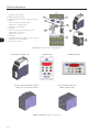
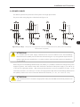
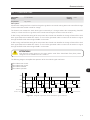
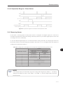
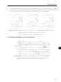
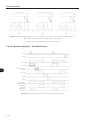
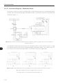
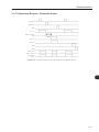
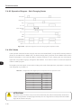
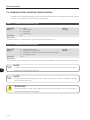
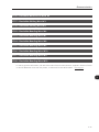
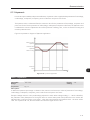
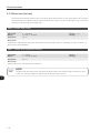
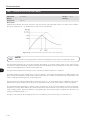
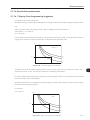
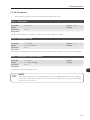
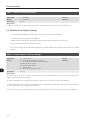
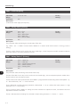
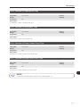
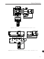
5.4.4.2 Operation Diagram – Direct Starter
Start
Stop
O1 - K1
TRIP
Reset
Check Back Motor
current / Input I3
Figure 5.8 - Operation diagram for the Direct Starter Operation Mode
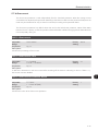
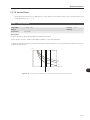
5.4.5 Reversing Starter
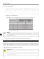
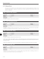
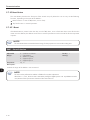
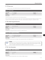
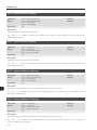
In this mode a reversing starter for three-phase motors is configured. The digital outputs O1 and O2 are
reserved for the operation of the motor starting contactors (internal use). The other digital outputs can be used
according to the user’s needs (free).
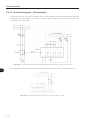
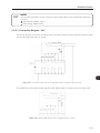
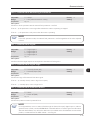
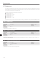
In case of a TRIP, the digital outputs O1 and O2 switch off the starting contactors, thus stopping the motor. For
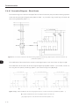
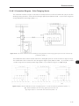
the Control Unit (UC) connection diagram presented in the section 5.4.5.1, the digital inputs and outputs are
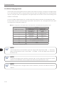
configured according to the table 5.5.
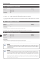
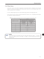
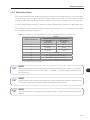
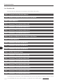
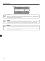
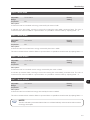
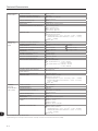
Table 5.5 - Configuration of the digital inputs and outputs for the Reverter Starting operation mode
Function
Digital Inputs /Outputs
I1
5
Local/Remote Commands using Digital Inputs
Control Logic
3 wires (P230 = 1)
(Pushbuttons)
Control Logic
2 wires (P230 = 0)
(Switch)
Stop Pushbutton
Free
I2
Direct ON Button
Direct ON/OFF switch
I3
Reverse ON Button
Reverse ON/OFF switch
I4 (*)
Check Back
O1
Forward Contactor Operation
O2
Reverse Contactor Operation
O3
Ladder
O4
Ladder
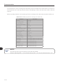
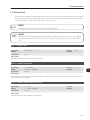
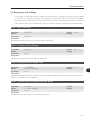
(*) Adjust P208 according to the application.
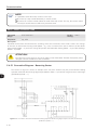
NOTE!
In the example above, the Check Back signal was configured for digital input, P208 = 1. The factory
setting is Check Back by motor current, P208 = 0. If P208 = 0, then the digital input I4 becomes
free for the user.
5-17