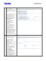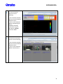
1
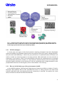
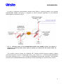
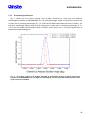
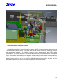
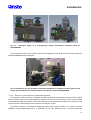
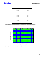
KOOKABURRA
The Ultra-Small-Angle Neutron Scattering
(USANS) Instrument
KOOKABURRA
USER MANUAL
KOOKABURRA
Table of Contents
1
TECHNICAL DESCRIPTION .....................................................................................................................................3
1.1 INTRODUCTION ...................................................................................................................................................... 3
1.2 ABOUT USANS ........................................................................................................................................................ 3
1.2.1
USANS TECHNIQUES ..................................................................................................................................... 4
1.2.2
HOW WE DECIDED WHAT TYPE OF LOW-Q INSTRUMENT TO BUILD ........................................................... 4
1.3 THE KOOKABURRA USANS INSTRUMENT ............................................................................................................... 5
1.3.1
INSTRUMENT CONCEPT ................................................................................................................................ 6
1.3.2
INSTRUMENT PERFORMANCE..................................................................................................................... 10
1.3.3
INSTRUMENT LAYOUT................................................................................................................................. 11
1.3.4
INSTRUMENT COMPONENTS ...................................................................................................................... 13
1.3.4.1
1.3.4.2
1.3.4.3
1.3.4.4
1.3.4.5
1.3.4.6
1.3.4.7
1.3.4.8
1.4
2
COLD-NEUTRON GUIDE CG3 ............................................................................................................................... 13
PREMONOCHROMATOR ASSEMBLY ................................................................................................................... 14
BERYLLIUM FILTER .............................................................................................................................................. 16
SAMPLE SHUTTER AND BEAM STOP ................................................................................................................... 17
CHANNEL-CUT MONOCHROMATOR/ANALYSER STAGES.................................................................................... 17
SLIT SYSTEMS ...................................................................................................................................................... 20
SAMPLE STAGE ................................................................................................................................................... 20
DETECTOR SYSTEM AND DATA TREATMENT/MANAGEMENT ............................................................................ 22
REFERENCES ......................................................................................................................................................... 24
USER GUIDE FOR INSTRUMENT OPERATION ....................................................................................................... 25
2.1 PRELIMINARIES ..................................................................................................................................................... 25
2.1.1
WAVELENGTH OPTIONS .............................................................................................................................. 25
2.1.2
SAMPLE REQUIREMENTS ............................................................................................................................ 25
2.1.3
SAMPLE MOUNTING ................................................................................................................................... 27
2.1.4
SAMPLE ENVIRONMENT ............................................................................................................................. 28
2.2 OPERATION OF KOOKABURRA ............................................................................................................................. 28
2.3 ILLUSTRATED STEP-BY-STEP INSTRUCTIONS ........................................................................................................ 29
2
KOOKABURRA
1
1.1
TECHNICAL DESCRIPTION
INTRODUCTION
This document provides a comprehensive technical description of the ultra-small-angle neutron
scattering (USANS) instrument KOOKABURRA installed at the ANSTO OPAL reactor, where a brief
overview of USANS techniques and applications is followed by a general description of the layout
and performance of KOOKABURRA.
1.2
ABOUT USANS
Modern materials science and engineering rely increasingly on a detailed knowledge of the
interplay between structure and material properties, and
Modern materials science and
neutron scattering is a key tool for obtaining structural
engineering rely increasingly on a
information.
detailed knowledge of the
In small-angle neutron scattering (SANS) experiments,
microstructure and interactions in
neutrons are assumed to be elastically scattered by a
soft and hard materials.
sample, and the resulting scattering pattern can be
analysed to provide information about the size, shape,
orientation, and number density of scattering entities within the sample. SANS can provide a
unique insight into the hierarchical structures of materials because the range of accessible realspace length scales D is relatively large, ranging between 10 Å and a few 1,000 Å, with the
corresponding scattering vector magnitudes Q ≅ 2π/D ranging between ∼1 and ∼10-3 Å-1 [Q = |Q|=
(4πλ) sin(θ/2), where θ is the scattering angle and λ is the wavelength of the incident neutrons]. In
many experimental cases, it is desirable to extend this experimentally
The USANS technique
measurable range to length scales up to D = 105 Å = 10 µm,
allows determination of
corresponding to Q ≅ 10-4 Å-1, the "ultra-low-Q" region accessible
microstructures (size,
through ultra-small-angle neutron scattering, USANS.
shape, orientation, etc.)
of complex systems
USANS is useful for studies of pores and cracks in rocks, cement or
covering length scales
engineering materials, very large biological or polymer molecules or
in the range of ∼100 nm
macromolecular assemblies, and mesoscopic magnetic particles. The
to ∼10µm.
range of interest includes bacteria, blood, cements, clays, clusters in
metals, coals, colloids, complex fluids, emulsions, foams, food, gels,
granular materials, hydrogels, membranes, micellar systems, minerals
and mineral processing, nanocomposites, nanotechnology, phase
transitions, polymer blends, polymers, porous materials, powders,
precipitates, proteins, rocks, thin metallic or organic films, viruses, etc.
3
KOOKABURRA
Fig. 1 - Example of three high-level research areas that benefit from applying the USANS technique,
see three blue circles. Listed next to them are associated areas of interest. It follows that there is a
broad range of materials that may be studied by USANS.
1.2.1
USANS techniques
In recent years two types of ultra-low-Q neutron scattering techniques have been developed,
namely the double-crystal USANS method, which uses perfect silicon (Si) crystals in Bragg reflection,
and spin-echo SANS (SESANS), in which the spin precessions of a polarised beam of neutrons are
used to encode the scattering angle to very high precision. Both techniques are only sensitive to
scattering in one direction, while in the perpendicular direction the measurements are averaged
over the possible wavevector transfers, i.e. they measure scattered intensity from the sample with
excellent angular resolution in one direction of a few arc seconds but with a large acceptance in the
perpendicular direction of a few degrees, which is described as "slit smearing".
1.2.2
How we decided what type of low-q instrument to build
At the ANSTO workshop "Pushing Small-Angle Neutron Scattering at OPAL to Smaller Q" held in
November 2007 (ANSTO, 2007) it was concluded that there is a strong scientific case with broad
scientific application and a pre-existing low-Q user community in Australia. Two options for a new
low-Q instrument to be built at OPAL were defined:
4
KOOKABURRA
•
Classical Double-Crystal USANS
This method, also known as Bonse-Hart method (Bonse & Hart, 1965), uses two
perfect Si crystals in Bragg reflection as collimators.
•
Spin-Echo SANS (SESANS)
This recently developed method uses spin precessions of a polarised neutron beam
to encode the scattering angle to very high precision.
To help decide on the most appropriate type of instrument for the Australian community, we
have carried out a detailed comparison of the capabilities of both methods. Based on experimental
round-robin test measurements as well as analytical calculations, we analysed the strengths,
weaknesses and experimental limitations, and investigated possible performance gains for both setups at OPAL.
•
Round-Robin Neutron Scattering Measurements
Round-robin test measurements have been performed on a set of standard samples
using the BT-5 double-crystal USANS instrument at NIST (Barker et al., 2005) and the
SESANS instrument at Delft (Rekveldt et al., 2005), respectively, to experimentally
determine the advantages and disadvantages of both techniques. The standard
samples consisted of polystyrene microspheres featuring different particle diameters
and various scattering powers.
•
Instrument Performance Estimations
Monte Carlo and analytical calculations helped estimate the performances of either
instrument type, double-crystal USANS and SESANS, being installed at OPAL.
Although both techniques are applicable for studying large-scale objects they have different
strengths, and it follows that different science will be done on these two instruments which are
complementary rather than competitive. A survey of the Australian large-scale structures science
community revealed that a rather large range of scientific problems needs to be covered by the
new instrument. According to the experts, double-crystal USANS is better suited for investigating
the widest possible range of sample properties and the widest range of sample scattering powers.
A paper titled "DCD USANS and SESANS: a comparison of two neutron scattering techniques
applicable for the study of large-scale structures" has been published (Rehm et al., 2013).
1.3
THE KOOKABURRA USANS INSTRUMENT
The KOOKABURRA USANS instrument is based on the classical Bonse-Hart [Bonse & Hart, 1965)
method, which consists of using two multiple-reflection crystal systems arranged in a nondispersive geometry to achieve a steep decrease in the tails of the perfect crystal diffraction curves.
This technique permits the detection of very small angular deviations of the neutron beam after
scattering from a sample placed between two channel-cut crystals (Agamalian et al., 1997).
In the following we discuss the concept and layout of the KOOKABURRA double-crystal USANS
instrument followed by detailed descriptions of the instrument components (Rehm et al., 2013).
5
KOOKABURRA
1.3.1
Instrument concept
The central parts of KOOKABURRA are two identical, multi-bounce, channel-cut, perfect Si single
crystals (Schwahn et al., 1985), labelled monochromator and analyser (see Fig. 2) mounted on a
single optical bench. When the monochromator and analyser crystals are perfectly aligned to each
other (analyser rotation angle θ = 0˚), the incident neutron beam is totally reflected into the main
detector.
Fig. 2 - Schematic layout of the double-crystal USANS principle. The main instrument components
are two identical, perfect silicon (Si) channel-cut crystals placed in front (labelled monochromator)
and after the sample (labelled analyser), respectively. During the experiment the analyser crystal is
rotated and thus a very sharp rocking curve profile recorded.
During the experiment neutron scattering intensities are measured as a function of the
momentum transfer Q (or scattering angle θ) at a time, i.e. only the small-angle scattering
corresponding to the same angle θ is reflected. Minute deviations in the neutron beam direction
after scattering by the sample are observed as a broadening of the double-crystal analyser rocking
curve (see Fig. 3).
6
KOOKABURRA
Fig. 3 - In a typical double-crystal USANS experiment rocking curves are measured with and without
a sample material being present. Small-angle scattering caused by the sample material results in a
broadening of the initially sharp rocking curve profile, and the difference between these two rocking
curves will be analysed.
Because the channel-cut crystals are perfect, Bragg reflection of a particular wavelength λ is
restricted to a very narrow angular range of neutron trajectories that fall within the so-called
Darwin width, which is typically a few arc seconds (Agamalian et al., 1997: Barker et al., 2005).
Within this uncertainty, neutron trajectories are completely correlated with neutron wavelength.
The Bonse-Hart USANS technique can use a relatively wide range of wavelength/divergence-angle
combinations simultaneously, which enhances the flux on sample without sacrificing the Qresolution.
The high angular resolution required for double-crystal USANS experiments is enhanced through
multiple reflections of the neutron beam before and after the sample. KOOKABURRA utilises
quintuple bounces inside the perfect Si channel-cut crystals. Optimisation of the instrument with
regards to determining the most efficient type of premonochromator crystal, channel-cut crystals,
and scattering geometry has been discussed elsewhere (Freund & Rehm, 2011).
Note that in a traditional SANS experiment the optimal sample scatters between 5% and 20% of
the incident neutron beam. For the case of less than 5% scattering, the signal-to-noise ratio might
be poor (note that the lower limit depends somewhat on the shape of the scattering curve). For
scattering of more than 20% of the beam, the SANS intensity would be strong enough to create
noticeable multiple scattering, resulting in a shape-distorted scattering curve. For the strongly
scattering samples, an adequate sample optimisation (i.e. a reduction of the scattering) can often
be achieved by manipulating the sample via, for example, dilution, reduction in sample thickness or
contrast matching. Note that the scattering power of a sample is also proportional to λ2.
7
KOOKABURRA
In order to optimally accommodate samples which differ in scattering powers, the versatile
KOOKABURRA USANS instrument is designed to allow individual operation at two different
wavelengths as illustrated in Fig. 4.
Fig. 4 - Schematic layout of the KOOKABURRA double-crystal USANS principle. The perfect Si
channel-cut crystals of choice, either Si(111) or Si(311), are rotated into the neutron beam. For
details see text.
The incident neutron beams are reflected off a highly-oriented pyrolytic graphite (HOPG)
premonochromator crystal at a fixed angle of θBragg = 45°, either at λ = 4.74 Å using the HOPG(002)
first-order reflection or at λ = 2.37 Å using the HOPG(004) second-order reflection. The expected
performances of KOOKABURRA when operating at either wavelength are summarised in Table 1.
8
KOOKABURRA
HIGH-INTENSITY MODE
HIGH-RESOLUTION MODE
Weak Scattering Samples
Strong Scattering Samples
Wavelength
λ = 4.74 Å
λ = 2.37 Å
Premonochromator
HOPG(002) at θBragg = 45°
HOPG(004) at θBragg = 45°
Beryllium Filter
In
Out
Channel-Cut Crystals
Si(111) at θBragg = 49.2°
Si(311) at θBragg = 46.4°
Full Darwin Width
2∆θD = 21 µrad
2∆θD = 5.4 µrad
Minimum Momentum Transfer
Qmin = 2.8⋅10 Å
Qmin = 1.4⋅10 Å
Flux on Sample
190,000 n cm-2 s-1
23,000 n cm-2 s-1
-5
-1
-5
-1
Table 1 - KOOKABURRA Instrument performances expected for operation at two different
wavelengths. Note that the precise values for the full width at half-height depend on whether the
Darwin or the Ewald solution applies, see e.g. Agamalian et al. (2010).
When operating the instrument with 4.74 Å neutrons, two Si(111) channel-cut crystals will be
used at a Bragg angle of 49.2°. Also, a beryllium filter will be moved into the beam to remove by
scattering neutrons with wavelengths below 4 Å, i.e. to suppress higher-order wavelengths
emerging from the premonochromator. When operating the instrument with 2.37 Å neutrons, two
Si(311) channel-cut crystals will be used at a Bragg angle of 46.4°, and the beryllium filter will be
moved out of the beam. The 4.74 Å wavelength high-intensity operation mode is most appropriate
for weakly scattering samples but it should be noted that the four times larger full Darwin width for
the 4.74 Å operation of 2∆θD = 21 µrad (compared to a value of 2∆θD = 5.4 µrad for the 2.37 Å
operation) results in a poorer resolution at small values of Q (Qmin for 4.74 Å is a factor of two larger
than Qmin for 2.37 Å, see Table 1). Note that Qmin is estimated as Qmin ≅ 4π∆θD/λ (Agamalian, 2011).
Concerns about multiple scattering for strongly scattering samples can be addressed by switching to
the λ = 2.37 Å mode when necessary. Although both the first- and second-order neutrons will reach
the channel-cut monochromator crystal when the beryllium filter is moved out of the beam when
operating KOOKABURRA at 2.37 Å, the 4.74 Å neutrons will not be further transported through the
Si(311) channel-cut crystal set-up.
9
KOOKABURRA
1.3.2
Instrument performance
Fig. 5 shows the very sharp rocking curve profiles obtained by using the two different
wavelengths available at KOOKABURRA. For the long wavelength option using Si(111) channel-cut
crystals with a resulting wavelength of λ = 4.74 Å the full-width-half-maximum value is 0.0015°, for
the short wavelength option using Si(311) channel-cut crystals with a resulting wavelength of λ =
2.37 Å the full-width-half-maximum value is 0.0003°, both values are in very good agreement to
theoretically expected figures.
Fig. 5 - Very sharp rocking curve profiles obtained by using either Si(111) or Si(311) channel-cut
crystals on KOOKABURRA. The two different wavelengths and the full-width-half-maximum values
of the curves are indicated.
10
KOOKABURRA
1.3.3
Instrument layout
KOOKABURRA has been installed at the ANSTO OPAL (Kennedy et al., 2001; Robinson &
Kennedy, 2002; Kennedy, 2006) cold-neutron guide CG3 downstream of the EMU backscattering
instrument and upstream of the PLATYPUS reflectometer (James et al., 2006, 2011), see Fig. 6.
Fig. 6 - Neutron scattering instruments installed at the cold-neutron guide CG3 at the ANSTO OPAL
reactor.
The general assembly of KOOKABURRA is schematically shown in Fig. 7 while Fig. 8 shows a
photo of the instrument during the installation phase.
11
KOOKABURRA
Fig. 7 - General assembly of the KOOKABURRA USANS instrument at the ANSTO OPAL cold-neutron
guide CG3 with main components indicated.
A doubly focusing highly-oriented pyrolytic graphite (HOPG) premonochromator device extracts
a monochromatic neutron beam. A beryllium filter can be used to remove by scattering neutrons
with wavelengths below 4 Å, if required. A sample shutter allows opening and closing of the
neutron beam. The sample position is surrounded by the channel-cut monochromator and analyser
stages. The distance between these two stages is variable in order to be able to accommodate any
sample environment equipment like cryostats, magnets etc. It follows that the location of the main
detector (which needs to be in line with the channel-cut analyser crystal) is variable, too. For
detailed descriptions of the main instrument components see sections below.
12
KOOKABURRA
Fig. 8 - The KOOKABURRA USANS instrument during the installation phase.
1.3.4
Instrument components
1.3.4.1 Cold-neutron guide CG3
KOOKABURRA utilises neutrons delivered by the OPAL cold-neutron guide CG3. This guide is fed
by a hydrogen cold-neutron source 363 mm high × 108 mm wide with a total flux of 1.8×10⁻¹³ n
cm-2 s-1 at T = 25 K (Kennedy, 2006). CG3 includes straight neutron guide sections with curved
neutron guide sections in between (with a radius of curvature of 1.3 km), supermirror coatings of m
= 3 at the top and bottom of the neutron guides and m = 2.5 on the sides, a cut-off wavelength of
about λ = 0.8 Å, and a beam cross-section 200 mm high × 50 mm wide. The upper 20 mm of CG3
are exclusively used to provide neutrons to the PLATYPUS neutron reflectometer installed
downstream of KOOKABURRA. Therefore, the remaining effective beam cross-section for
KOOKABURRA is 170 mm high × 50 mm wide.
Fig. 9 shows the schematic layout of the KOOKABURRA upstream optics (CG3 neutron guide,
premonochromator assembly, beryllium (Be) filter on a translation stage, and the sample shutter).
13
KOOKABURRA
Fig. 9 - Schematic layout of the KOOKABURRA upstream optics with main components indicated.
1.3.4.2 Premonochromator assembly
About 30 m away from the cold source, a premonochromator crystal has been installed in the
white neutron beam exiting the cold-neutron guide CG3 of effective dimensions 170 mm high × 50
mm wide. Its function is to select a monochromatic neutron beam and to focus it onto the sample
position, which is located between the channel-cut monochromator and the channel-cut analyser
crystal at a nominal distance of 1600 mm from the premonochromator. The schematic layout of the
premonochromator assembly, comprising of the premonochromator crystal and tilt and rotation
stages for its alignment, is shown in Fig. 10.
Fig. 10 - Left: Schematic layout of the KOOKABURRA premonochromator assembly with main
components indicated. Right: Premonochromator crystal mounting.
14
KOOKABURRA
The premonochromator crystal material is highly-oriented pyrolytic graphite (HOPG) with
dimensions 82.5 mm (horizontal) × 168 mm (vertical) × 1.8 mm thick. Since the premonochromator
is doubly focusing (i.e. it is curved both horizontally and vertically), it consists of a composite of five
vertical arrays of 17 HOPG pieces, each piece with dimensions 16.5 mm (horizontal) × 10 mm
(vertical). The pieces were mounted on a silicon support plate (SESO, http://www.seso.com)
approaching the nominal curvatures with a sagittal (vertical) radius of curvature of 2.27 m, and a
meridional (horizontal) radius of curvature of 4.54 m, using indium metal as bonding material. The
Bragg angle of the assembled premonochromator crystal is fixed at 45°.
The crystal assembly was characterised on the double-crystal test instrument T13C of the
Institute Laue-Langevin (ILL) in Grenoble, France (Boeuf et al., 1975), using the HOPG(004)
reflection at a Bragg angle of 45° with a corresponding wavelength of 2.37 Å. The neutron mosaic
spread was measured to be ∼0.6° at FWHM in both the horizontal and vertical directions, while the
average peak reflectivities were determined as 44.7% ± 5.5% in the sagittal and 44.0% ± 2.6% in the
meridional direction, respectively. These figures show that the HOPG material is of excellent quality
and that the mosaic spread is isotropic.
The use of such a doubly focusing premonochromator leads the significantly enhanced neutron
intensity at the sample position (Freund & Rehm 2011). The premonochromator crystal is mounted
on tilt and rotation stages to allow position control (ADC: Advanced Design Consulting,
http://www.adc9001.com).
15
KOOKABURRA
1.3.4.3 Beryllium filter
Since KOOKABURRA enables individual operation at either λ = 4.74 Å or λ = 2.37 Å, a beryllium
(Be) filter is required to absorb higher-order wavelengths when operating the instrument at λ =
4.74 Å. The Be filter is moved out of the neutron beam when KOOKABURRA operates at λ = 2.37 Å
via a linear stage (Huber, http://www.xhuber.com). Details of the Be filter and its location inside the
premonochromator shielding bunker are shown in Fig. 11.
Fig. 11 - Left: Schematic layout of the KOOKABURRA Be filter assembly with main components
indicated. Right: Locations of premonochromator stage and Be filter inside the shielding bunker.
The beryllium material is made of the highly pure and isotropic S-200-F standard grade, which
contains very low amounts of hydrogen (Materion, http://www.materion.com; formerly Brush
Wellman company). One block of polycrystalline beryllium (where the average grain size is 8.6 µm
and theoretical density is 99.99%) with dimensions 60 mm (horizontal) × 170 mm (vertical) × 150
mm thick along the neutron path is surrounded on four sides by 2.3 mm thick BORTEC (Al-B4C metal
matrix composite with 16% B4C) sheets plus an additional outer layer of 0.5 mm thick cadmium
(Cd). Placed inside a vacuum shroud made from aluminium (Janis, http://www.janis.com), the
Be/BORTEC/Cd assembly is mounted to a 10 mm thick copper frame. Since cooling of the filter has a
large effect on the transmission of the Be (the transmission of 4 Å neutrons through Be is increased
by 125 ± 5% on cooling from 300 K to 80 K), a cooling system (closed cycle refrigerator, air cooled)
and an associated vacuum system are also required.
16
KOOKABURRA
1.3.4.4 Sample shutter and beam stop
A sample shutter (or beam shutter) allows the opening and closing of the neutron beam. The
premonochromator shielding bunker, which houses the premonochromator crystal assembly and
the beryllium filter, features 200 mm thick lead walls lined with 5 mm thick borated rubber in order
to achieve radiological doses outside the bunker below the design limit of ≤ 3 µSv/h. The sample
shutter is mounted to the outside of that bunker.
A re-entrant, fixed beam stop stops the diffracted beam past the channel-cut monochromator
crystal. Its opening is 155 mm (horizontal) × 275 mm (vertical) with a depth of 200 mm. The lead
thickness is 50 mm with its inside lined with 5 mm thick
borated rubber, see Fig. 12.
1.3.4.5 Channel-cut monochromator/analyser stages
All four channel-cut crystals used on KOOKABURRA, i.e.
two Si(111) channel-cut crystals and two Si(311) channelcut crystals (manufactured by Holm, http://www.holmsilicon.de), were satisfactorily characterised on the neutron
optics instrument S18 at the ILL (Kroupa et al., 2000), which
was configured as a high-resolution Bonse-Hart camera
using the Si(333) reflection at a Bragg angle of 45° with a
corresponding wavelength of 1.48 Å.
At the KOOKABURRA channel-cut monochromator (CCM) stage (before the sample position) both a Si(111) and a
Si(311) channel-cut monochromator crystal are mounted
on a granite base plate back-to-back with a sidewise offset,
so that the beam centre is aligned on first reflection for
both crystals with respect to the premonochromator
crystal. The Bragg angle for the Si(111) crystals is 49.2° (for
λ = 4.74 Å), while the Bragg angle for the Si(311) crystals is
46.4° (for λ = 2.37 Å). Therefore, the respective neutron
beam paths between monochromator and analyser crystals
differ by a few degrees. The schematic layout of the
channel-cut crystals is shown in Fig. 13.
Fig. 12 - KOOKABURRA Beam stop.
17
KOOKABURRA
Fig. 13 - Schematic layout of two sets of channel-cut crystals mounted inside circular shielding boxes
on top of the optical granite table. CC-M: channel-cut monochromator; CC-A: channel-cut analyser
positioned 600 mm away from CC-M; CC-A': channel-cut analyser positioned 1,100 mm away from
CC-M. Top: Using Si(111) at 49.2°. Bottom: Using Si(311) at 46.4°. For details see text.
The top layout in Fig. 13 depicts the setup used when operating KOOKABURRA at λ = 4.74 Å. The
neutron beam (shown in red) enters and leaves the Si(111) monochromator crystal (shown in
green) at 49.2° relative to the beam coming off the premonochromator, before entering and
18
KOOKABURRA
leaving the Si(111) analyser crystal (also shown in green). The paths of the neutron beams
transmitted towards the transmission detector and beam stop, respectively, are indicated in blue.
The minimum distance between the channel-cut monochromator CC-M and the channel-cut
analyser CC-A of 600 mm can be variably increased to up to 1,100 mm for accommodation of any
sample environment equipment (note that in Fig. 13 the position of the channel-cut analyser stage
for the maximum distance of 1,100 mm is labelled CC-A'). The bottom layout in Fig. 13 shows the
setup used when operating KOOKABURRA at λ = 2.37 Å. The Si(311) crystals (shown in pink) are
rotated into the neutron beam at an angle of 46.4° relative to the beam coming off the
premonochromator.
The channel-cut monochromator and analyser crystals are housed in two separate, shielded
monochromator/analyser boxes made from aluminium, lined with boron plastic, and furnished with
beam entrance and exit cut-outs, see Fig. 14.
Fig. 14 - Arrangement of two sets of channel-cut monochromator- and analyser crystals as indicated
by the arrows.
Alignment of the channel-cut monochromator crystal in use can be done via tilt, rotation, and
linear translation stages (ADC) beneath the granite base plate. When swapping between channelcut monochromator crystals, i.e. between the two wavelengths, both shielded boxes will be rotated
by 180°. The same arrangement as described above for the channel-cut monochromator stage is
valid for the channel-cut analyser stage located after the sample position. Both channel-cut
monochromator and analyser stages are mounted on a single optical table made from granite
(ADC). The total weight of the (loaded) granite table is about 1.3 tons; this reduces the impact of
external vibrations on the relative angle of the monochromator and analyser channel-cut crystals,
which determines the angular resolution of the instrument.
19
KOOKABURRA
1.3.4.6 Slit systems
On KOOKABURRA two motorised slit systems (ADC) are used to define the dimensions of the
neutron beam before and after the sample, see Fig. 15 for their schematic layout. The first slit
system is placed between the channel-cut monochromator stage and the sample stage. Its opening
is 0 mm - 115 mm in horizontal direction and 0 mm - 70 mm in vertical direction. The wider opening
in the horizontal direction takes into account the two different Bragg angles of the channel-cut
crystals, or two different neutron beam paths, required when operating the instrument at two
different wavelengths (see Fig. 13). A second slit system is placed between the channel-cut analyser
stage and the main detector. Its opening is 0 mm - 70 mm in both the horizontal and vertical
directions. The openings of both slit systems are adjustable through four separate blades in the
up/down/left/right directions, each controlled by motors and encoders. The material of the slit
blades is sintered B4C of 5 mm thickness.
Fig. 15 - KOOKABURRA Slit systems (the slit shown on the left has been installed between the
channel-cut monochromator crystal and the sample position, the slit shown on the right has been
installed between channel-cut analyser crystal and the main detector, for details see text.
During operation, the maximum opening of the slit systems corresponds to the maximum beam
size transmitted through the channel-cut monochromator and channel-cut analyser crystal of 50
mm × 50 mm. This value also determines the maximum sample size.
1.3.4.7 Sample stage
For routine experiments, a multi-position sample changer is used to successively position various
samples in the neutron beam centre using a linear translation stage. To this end the distance
between channel-cut monochromator and analyser stage is at its minimum of 600 mm (see Fig. 13).
For experiments requiring any sample environment equipment the distance between the two
stages can be increased variably up to a maximum of 1,100 mm by moving the channel-cut analyser
20
KOOKABURRA
stage away from the sample position as illustrated in Fig. 16. In the latter case the beam intensity
will be reduced by a factor of 0.7 from the effect of defocusing.
Fig. 16 - Top: Location of channel-cut analyser (CC-A) stage during routine experiments using a multiposition sample changer (not shown for clarity). Bottom: Moving the CC-A stage further
downstream allows accommodation of sample environment equipment between the
monochromator and analyser crystals.
The sample changer as well as any sample environment equipment is independently supported
by an appropriate table, which is not in contact with the optical table in order not to transfer
vibrations to the highly sensitive arrangement of the channel-cut crystals. For a schematic layout of
such table see Fig. 17.
21
KOOKABURRA
Fig. 17 - Schematic layout of a self-supporting sample environment equipment table for
KOOKABURRA.
As an example of the use of sample environment equipment Fig. 18 shows a rheometer placed in
the KOOKABURRA sample position.
Fig. 18: Example for the use of sample environment equipment: a rheometer has been placed in the
sample position between the monochromator and analyser crystals of KOOKABURRA.
1.3.4.8 Detector system and data treatment/management
The detector system consists of a beam monitor required to record the intensity of the incident
neutron beam, two transmission detectors required to monitor the intensity of the neutron beam
transmitted through the sample, and a main detector array required to measure the intensity of the
neutron beam transmitted past the channel-cut analyser crystal.
The beam monitor is installed immediately behind the sample shutter as a neutron counter
(ORDELA, http://www.ordela.com). It operates at low 3He pressure with a neutron detection
22
KOOKABURRA
efficiency of ∼ 5×10⁻⁶ at 15 meV (2.3 Å). Both transmission and main detectors consist of 3He filled,
5 inch (1 inch = 25.4 mm) long position-sensitive detector tubes (GE, http://www.ge-energy.com).
The operation of KOOKABURRA at two different wavelengths requires a set of two individual
detectors to measure the transmitted beam (with efficiencies of ∼ 1% for λ = 4.74 Å and ∼ 10% for
λ = 2.37 Å). The two transmission detector tubes (diameter = 2.5 inch) are mounted next to each
other on a shielded support structure. The main detector consists of a hexagonal array of five 3He
detector tubes (diameter = 1 inch) with two tubes in the front and three tubes in the back inside a
shielding box made from Cd-lined borated polyethylene to protect the detector tubes from stray
neutrons.
Given that the distance between channel-cut monochromator and channel-cut analyser stages is
variable, the main detector shielding box is mounted on a linear stage (ADC) which follows the
position of the channel-cut analyser crystal (see Fig. 16). Besides the main detector shielding box
and the linear stage, the detector support structure also holds the second slit system as well as a
beam attenuator kit comprising plexiglass plates of different thicknesses on a small linear stage
(HIWIN, http://www.hiwin.com).
Instrument control, data acquisition, experimental planning, and data analysis of the
KOOKABURRA USANS instrument is carried out by a computerised system consisting of the
following: i) a data acquisition computer directly interfaced with the USANS detector electronics
complete with histogram memory software, ii) SICS (SINQ Instrument Control System) computer
server software (Herr et al., 1997), and iii) GumTree user application software (Lam et al., 2006).
Reduced USANS data can be analysed using model-independent methods or non-linear fitting to
one of a large and growing catalogue of structural models which has been developed at the NIST
Center for Neutron Research (Kline, 2006).
23
KOOKABURRA
1.4
REFERENCES
Agamalian, M., Wignall, G.D. & Triolo, R. (1997). J. Appl. Cryst., 30, 345-352.
Agamalian, M., Carpenter, J.M. & Treimer, W. (2010). J. Appl. Cryst., 43, 900-906.
Agamalian, M. (2011). Bonse-Hart USANS Instrument, ch. II.1.3.1 in Neutrons in Soft Matter,
edited by T. Imae, T. Kanaya, M. Furusaka & N. Torikai, pp. 73-93. Hoboken: John Wiley and
Sons.
ANSTO (2007). Workshop Report "Pushing Small-Angle Neutron Scattering at OPAL to Smaller
Q".
Barker, J.G., Glinka, C.J., Moyer, J.J., Kim, M.H., Drews, A.R. & Agamalian, M. (2005). J. Appl.
Cryst., 38, 1004-1011.
Boeuf, A., Gobert, G. & Rustichelli, F. (1975). Nucl. Instrum. Methods, 124, 533-540.
Bonse, U. & Hart, M. (1965). Appl. Phys. Lett., 7, 238.
Freund, A.K. & Rehm, C. (2011). Nucl. Instrum. Methods Phys. Res. Sect. A, 634, 581-589.
Herr, H., Könnecke, M. & Maden, D. (1997). Physica B, 241-243, 124-126.
James, M., Nelson, A., Brule, A. & Schulz, J.C. (2006). J. Neutron Res., 14, 91-108.
James, M., Nelson, A., Holt, S.A., Saerbeck, T., Hamilton, W.A. & Klose, F. (2011). Nucl.
Instrum. Methods Phys. Res. Sect. A, 632, 112-123.
Kennedy, S. J., Robinson, R. A. & Hunter, B. A. (2001). J. Phys. Soc. Jpn, 70 (Suppl. A), 567–570.
Kennedy, S. (2006). Physica B, 385-386, 949-954.
Kline, S.R. (2006). J. Appl. Cryst., 39, 895-900.
Kroupa, G., Bruckner, G., Bolik, O., Zawisky, M., Hainbuchner, M., Badurek, G., Buchelt, R.J.,
Schricker, A. & Rauch, H. (2000). Nucl. Instrum. Methods Phys. Res. Sect. A, 440, 604-608.
Lam, T., Hauser, N., Götz, A., Hathaway, P., Franceschini, F., Rayner, H. & Zhang, L. (2006).
Physics B, 385-386, 1330-1332.
Rekveldt, M. T., Plomp, J., Bouwman, W. G., Kraan, W. H., Grigoriev, S. & Blaauw, M. (2005).
Rev. Sci. Instrum., 76, 033901.
Rehm, C., Barker, J., Bouwman, W.G. & Pynn, R. (2013). J. Appl. Cryst., 46, 354–364.
Rehm, C., Brule, A., Freund, A.K. & Kennedy S.J. (2013). J. Appl. Cryst., 46, 1699-1704.
Robinson, R. A. & Kennedy, S. J. (2002). Physica B, 311, 44–49.
Schwahn, D., Miksovsky, A., Rauch, H., Seidel, E. & Zugarek G. (1985). Nucl. Instrum. Methods
Phys. Res. Sect. A, 239, 229-234.
24
KOOKABURRA
2
USER GUIDE FOR INSTRUMENT OPERATION
The purpose of this section is to provide instructions for the use of the ultra-small-angle neutron
scattering (USANS) instrument KOOKABURRA. A comprehensive technical description of the
instrument concept, layout, components, and performance is provided in the previous chapter.
2.1
PRELIMINARIES
2.1.1
Wavelength options
KOOKABURRA can individually be operated at two different wavelengths to optimally
accommodate weakly and strongly scattering samples in one sample position. Depending on the
specific scattering powers of sample material provided by the users a wavelength of either λ = 4.74
Å or λ = 2.37 Å neutrons is selected as follows:
•
The 4.74 Å wavelength high-intensity operation mode is most appropriate for weakly
scattering samples.
•
The 2.37 Å wavelength high-resolution operation mode is most appropriate for
strongly scattering samples.
For meaningful USANS data collection it needs to be thought through which wavelength option
can be considered the most appropriate one for the sample material to be investigated. Ideally such
decision is based on a reasonable comparison to similar previous experiments or simulated data.
The proper choice of wavelength will be verified by quick scans performed prior to full USANS
scans.
2.1.2
Sample requirements
The Q-range accessible on KOOKABURRA starts from Q = 1.8⋅10-5 Å-1 for the short and Q = 3⋅10-5
Å-1 for the long wavelength, and goes up to about Q = 1⋅10-2 Å-1 depending on the sample
morphology which determines at which Q the background will be reached. Details of preliminary
measurements and/or simulation calculations provided help determine the Q-range of interest for
individual experiments. As a rough guide, an absolute intensity of 10-100 cm-1 is required for the
long wavelength, and about 10,000-100,000 cm-1 for the short wavelength to detect a USANS
signal.
The maximum neutron beam cross section to be used on KOOKABURRA is 50 mm x 50 mm.
Therefore, wherever feasible, enough sample material should be provided by the users to ensure
an adequate use of the beam. Table 1 lists the neutron beam intensity as a function of the beam
size (cross-section), the data are also plotted in Fig. 1. According to the figures presented, a sample
size of about 30 mm x 30 mm and above is preferred. Large beam areas will not only speed up
experiments, but also result in improved data (better signal-to-noise ratio at high Q).
25
KOOKABURRA
2
Neutron Beam Cross-Section (mm )
Neutron Beam Intensity
50 x 50
100%
45 x 45
98%
40 x 40
90%
35 x 35
85%
30 x 30
75%
25 x 25
55%
20 x 20
40%
15 x 15
25%
10 x 10
15%
5x5
5%
Table 1 - Expected neutron beam intensities as a function of the utilised beam cross section.
100
Neutron Beam Intensity (%)
90
80
70
60
50
40
30
20
10
0
0
10
20
30
40
50
2
Pre-Sample Slit Opening (mm )
Fig. 1 - Expected beam intensities as a function of the utilised neutron beam cross section.
26
KOOKABURRA
2.1.3
Sample mounting
Samples that don't require a container like e.g. rock slabs or other solid specimens can directly
be mounted on a holding frame. For any other sample material like liquids, gels, powders, etc.
demountable KOOKABURRA sample cells are available with variable path lengths of "0", 1, 2, 5, and
10 mm and variable cross sections of 10 x 10, 20 x 20, 30 x 30, 40 x 40, and 50 x 50 in units of mm2,
see Fig. 2.
Fig. 2 - Top photos: Components of KOOKABURRA demountable sample cells. Sketch: Exemplary
KOOKABURRA cell inserts defining the sample size. Lower right photo: QUOKKA and KOOKABURRA
demountable sample cells side by side (window sizes 19 mm diameter and 50 mm × 50 mm,
respectively).
Note that the standard QUOKKA demountable sample cells and QUOKKA banjo cell holders (both
with a maximum neutron beam cross section of 19 mm in diameter) can also be easily
accommodated on the KOOKABURRA instrument which utilises a standard five-position sample
changer, although increased sample areas usually result in superior data.
Both the QUOKKA and the KOOKABURRA cells can be inserted into the sample holder
compartments of the five-position sample changer using appropriate adapter plates. Note that the
sample changer moves in vertical direction.
27
KOOKABURRA
2.1.4
Sample environment
There is a range of sample environment (SE) equipment which may be used on KOOKABURRA for
in-situ measurements of the sample within a controlled environment. Users must refer to the
relevant instruction manual for the equipment being used. A dedicated support structure for SE
equipment is available on the instrument. When SE equipment is used, the standard five-position
sample changer can not be available at the same time. If users plan to bring their own equipment it
needs to be checked by the ANSTO/Bragg sample environment team prior to the experiment.
2.2
OPERATION OF KOOKABURRA
Prior to the experiments users will be given an induction to the correct use of the KOOKABURRA
instrument. This will enable them to independently
•
•
•
•
•
mount and remove samples on KOOKABURRA
leave the experiment area and lock the access door
open and close the sample shutter
operate the instrument/control equipment within allowed limits
run experiments by following the procedure given below:
o start GUMTREE/SICS
o input information about user and sample
o start scans
o control experiment periodically using GUI
o repeat scans according to the experiment program
o stop/pause experiment
o close sample shutter
o go to instrument
o remove or change sample
o check samples for activation
o obtain sample clearance certifications
Illustrated step-by-step instructions for running experiments are provided in the next section. At
the end of the experiments all users will be provided with a complete data package including a copy
of the relevant pages of the KOOKABURRA logbook.
28
KOOKABURRA
2.3
ILLUSTRATED STEP-BY-STEP INSTRUCTIONS
1
On the desktop of the instrument
control computer double-click the
shortcut labelled "Gumtree 1.10.5"
(normally, this would already be
open)
2
New windows will open on the
screen.
Log on as follows:
For "Role" select Manager, then
type in the password ansto
If Gumtree won't start click
"Cancel" or try to close the
window. Then do the following:
1. On the desktop double-click
the shortcut labelled "PuTTY"
2. Double-click "kookaburra@ics"
3. Use password kookaburra123
4. Type runsics status
5. If SICS is running you should read
"sics listening on port..."
6. If SICS is not running type runsics
start
7. If SICS is unresponsive type
runsics stop, then runsics start
9. If SICS is now running close the
PuTTY window and start Gumtree
29
KOOKABURRA
again
3
Two new windows should now
open:
"SICS Experiment - SICS - Gumtree"
and "Analysis Scripting - Gumtree"
First window "SICS Experiment SICS - Gumtree"
The dark grey panel on the right
side of this window provides an
overview of the current status of
the reactor source and the current
motor positions of KOOKABURRA
instrument components
(Premonochromator, Beryllium
Filter, Channel-Cut
Monochromator, Pre-Sample Slit
System 1, Sample Positioner,
Channel-Cut Analyser, Post-Sample
Slit
System 2, Beam Attenuator, Main
Detector, Environment
Controllers).
For normal user operation the
only important features in the
window "SICS Experiment SICS - Gumtree" are
- the option to pause/resume
counting by clicking the pause
button
30
KOOKABURRA
- the option to fully stop the
current experiment by clicking
the big red stop button
Second window "Analysis
Scripting - Gumtree"
In this window we will load a script
for setting up and running an
experiment
4
1. Click the "Load Script" button
2. Click on "Open file..."
3. Select "KKB-Scan.py"
(the path is V:\shared\KKB
Scripts\KKB-Scan.py)
31
KOOKABURRA
Fill in all required
information for your sample,
then click on "Run Single
Scan"
If you want to measure
more samples one after the
other, the required
information per sample
needs to be saved under
"Save Single Scan
Parameters".
(the path for saving is
V:\shared\KKB
Logbook\Experiments External
Users\Configurations)
Then you need to click on
"Load Multiple Scan
Parameters" to create a
batch of scans. The
parameters of each loaded
scan can be read via the
dropdown menu. Click on
"Run Multiple Scans" to
execute the batch of scans.
5
To check the status of your
scan do the following:
1. Go to the window
"Analysis scripting Gumtree"
2. Click on "Window", then
"New Window"
3. Click the "Load Script"
button
2. Click on "Open file..."
3. Select "KKB-Plot.py"
(the path is
V:\shared\KKB
Scripts\KKB-Plot.py)
4. Load the data file you
want to look at by
clicking on the green plus
sign in the upper left
corner. Multiple files can
32
KOOKABURRA
be marked at once
(the path is
W:\data\current)
5. Highlight the file you
want to look at and click
on "Run"
6. To export the file click
on "Export to CSV"
7. Retrieve the exported
data from V:\shared\KKB
Logbook\Temp Plot Data
Repository to plot them
using the software of your
choice
NOTE:
Details of the samples,
neutron wavelength, and
environmental conditions
are recorded in the
KOOKABURRA electronic log
(HDF files). Details of
personnel, proposal
number, instrument
configuration, sample
environment used and any
other special features must
be recorded in the
KOOKABURRA manual
logbook.
Generation of the
electronic log is automatic
upon running a sample.
Path for electronic log (HDF files): W:\data\current
33
KOOKABURRA
6
To monitor detector
intensities do the
following:
1. On the desktop doubleclick the shortcut labelled
"Mozilla Firefox"
2. Click on the bookmark
labelled "KKB Histogram
Server"
3. Use the following
credentials to log on:
User Name: manager
Password: ansto
7
To check the instrument
cameras do the following:
1. On the desktop doubleclick the shortcut labelled
"Mozilla Firefox"
2. Click on the bookmark
labelled "KKB Cameras"
34