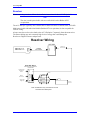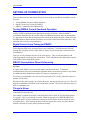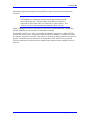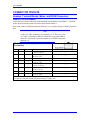
1
^1 USER MANUAL ^2 Accessory 8K2 ^3 Intelligent Power Block (IPB) Interface Board ^4 3Ax-602655-xUxx ^5 October 29, 2003 Single Source Machine Control Power // Flexibility // Ease of Use 21314 Lassen Street Chatsworth, CA 91311 // Tel. (818) 998-2095 Fax. (818) 998-7807 // www.deltatau.com Copyright Information © 2003 Delta Tau Data Systems, Inc. All rights reserved. This document is furnished for the customers of Delta Tau Data Systems, Inc. Other uses are unauthorized without written permission of Delta Tau Data Systems, Inc. Information contained in this manual may be updated from time-to-time due to product improvements, etc., and may not conform in every respect to former issues. To report errors or inconsistencies, call or email: Delta Tau Data Systems, Inc. Technical Support Phone: (818) 717-5656 Fax: (818) 998-7807 Email: [email protected] Website: http://www.deltatau.com Operating Conditions All Delta Tau Data Systems, Inc. motion controller products, accessories, and amplifiers contain static sensitive components that can be damaged by incorrect handling. When installing or handling Delta Tau Data Systems, Inc. products, avoid contact with highly insulated materials. Only qualified personnel should be allowed to handle this equipment. In the case of industrial applications, we expect our products to be protected from hazardous or conductive materials and/or environments that could cause harm to the controller by damaging components or causing electrical shorts. When our products are used in an industrial environment, install them into an industrial electrical cabinet or industrial PC to protect them from excessive or corrosive moisture, abnormal ambient temperatures, and conductive materials. If Delta Tau Data Systems, Inc. products are directly exposed to hazardous or conductive materials and/or environments, we cannot guarantee their operation. Accessory 8K2 Table of Contents INTRODUCTION ...................................................................................................................................... 1 OPTIONS.................................................................................................................................................... 3 LED INDICATORS ................................................................................................................................... 5 Watchdog Fault ........................................................................................................................................ 5 AMP1-ENA ............................................................................................................................................. 5 AMP1-FLT .............................................................................................................................................. 5 AMP2-ENA ............................................................................................................................................. 5 AMP2-FLT .............................................................................................................................................. 5 CONNECTORS.......................................................................................................................................... 7 JMACH1 .................................................................................................................................................. 7 P1 ............................................................................................................................................................. 7 P2 ............................................................................................................................................................. 7 P3 ............................................................................................................................................................. 7 P4 (Option 1B) ......................................................................................................................................... 7 P5 ............................................................................................................................................................. 7 P6 ............................................................................................................................................................. 7 P7 (Option 1B) ......................................................................................................................................... 7 P8 ............................................................................................................................................................. 7 TB1 .......................................................................................................................................................... 7 TB2 .......................................................................................................................................................... 7 TB3 (Option 1A)...................................................................................................................................... 8 TB4 (Option 1A)...................................................................................................................................... 8 TB5 (Option 1A)...................................................................................................................................... 8 TB6 (Option 1A)...................................................................................................................................... 8 TB7 (Assys 602655-102 and Later)......................................................................................................... 8 LAYOUT DIAGRAMS.............................................................................................................................. 9 I-VARIABLE ASSIGNMENTS .............................................................................................................. 11 Global Gate Array Variables.................................................................................................................. 11 Channel Specific Gate Array Variables ................................................................................................. 11 Motor I-Variables................................................................................................................................... 12 PMAC2, ENCODER, AND MOTOR INTERCONNECTION............................................................ 15 Motor...................................................................................................................................................... 15 Encoder .................................................................................................................................................. 16 Resolver ................................................................................................................................................. 17 SETTING UP COMMUTATION........................................................................................................... 19 Testing PWM & Current Feedback Operation....................................................................................... 19 Digital Current Loop Tuning for PMAC2 ............................................................................................. 19 PMAC2 Commutation Phase Referencing............................................................................................. 19 Things to Know...................................................................................................................................... 19 CONNECTOR PINOUTS ....................................................................................................................... 21 Headers, Terminal Blocks, Molex, and DSUB Connectors ................................................................... 21 JMACH (100-Pin Header)................................................................................................................. 21 P1 (8-Pin Power Supply Input Molex Connector)............................................................................. 21 P2 (12-Pin Current Feedback Molex Connector) ............................................................................. 22 P3 (16-Pin Command Output Molex Connector).............................................................................. 22 P4 (25-Pin Encoder and Hall-Effect Feedback DSUB Connector) {Option 1B only}...................... 23 P5 (12-Pin Current Feedback Molex Connector) ............................................................................. 24 P6 (16-Pin Command Output Molex Connector).............................................................................. 24 Table of Contents i Accessory 8K2 P7 (25-Pin Encoder and Hall-Effect DSUB Connector) {Option 1B only} ...................................... 25 P8 (14-Pin Sub Count Input Header)................................................................................................ 26 TB1 (6-Pin Input Flag Terminal Block) ............................................................................................ 26 TB2 (6-Pin Input Flag Terminal Block) ............................................................................................ 26 TB3 (8-Pin Encoder Interface Terminal Block) {Option 1A only}.................................................... 27 TB4 (10-Pin Hall-Effect Interface Terminal Block) {Option 1A}...................................................... 27 TB5 (8-Pin Encoder Interface Terminal Block) {Option 1A only}.................................................... 27 TB6 (10-Pin Hall-Effect Interface Terminal Block) {Option 1A only}.............................................. 28 TB7 (2-Pin Encoder Power Terminal Block) (Assys 602655-102 and later) .................................... 28 JUMPERS ................................................................................................................................................. 29 ii Table of Contents Accessory 8K2 INTRODUCTION PMAC2’s Accessory 8K2 (ACC-8K2) is a 2-axis board designed for easy connection to the Kollmorgen Industrial Drives Power Block product line. The ACC-8K2 allows the Industrial Drives Power Block (IPB) family of servo drivers (using IPB mode 1) to interface with the PMAC2 controller to provide the drive for 3-phasecommutated motors. The ACC-8K2 interface card provides the 3-phase outputs, analog phase current inputs, encoder and flag signals for each of the two axes. The drawing below shows the interconnection of the ACC-8K2, PMAC2, Motors, and servo amplifiers. Motor Phase Leads Shielded Cable; PWM & Phase Current Signals IPB Drive 1 JMACH 100 pin ACC8-K2 PMAC2 Encoder/Resolver, Optional Hall Effects Flags Flags Encoder/Resolver, Optional Hall Effects IPB Drive 2 Shielded Cable; PWM & Phase Current Signals Motor Phase Leads The PMAC2 can drive the commutation of a motor through a 3-phase servo amplifier accurately and efficiently using the two current sensors that are provided in the amplifier. Since the IPB product line provides these signals to PMAC2, then the current in a 3-phase permanent magnet brushless servomotor or AC induction motor may be monitored for precise commutation, resulting in precise control of each motor on a per-axis basis. ACC-8K2 is one of a series of I/O accessories for PMAC2. The interface to the PMAC2 is made using the JMACH connector cable. This 24inch (61cm) cable is supplied with the board. The ACC-8K2 has 16-pin Molex connectors for the amplifier command signals, 12-pin Molex connectors for the amplifier feedback signals and an 8-pin Molex connector for power. All of these connectors match the pinout at the IPB amp and power supply end so straight-across cables can be used. The ACC-8K2 (Option 1B) has two DB-25 connectors for the encoder and Hall Effect input signals. These connectors match the Kollmorgen quadrature encoder specification. Option 1A provides terminal connectors for alternate interconnection requirements. When used with the ACC-8K2, the PMAC2 provides three pairs of pulse trains, which have constant frequency and variable pulse width. This scheme is known as Pulse Width Modulation (PWM). Introduction 1 Accessory 8K2 2 Introductions Accessory 8K2 OPTIONS One of the following options must be selected when ordering the ACC-8K2: Option 1A - Encoder and Hall Effect inputs use terminals (TB3, TB4, TB5, TB6). Option 1B - Encoder and Hall Effect inputs use DSUB connectors (P4, P7). Options 3 Accessory 8K2 4 Options Accessory 8K2 LED INDICATORS Refer to the layout diagram of ACC-8K2 for the location of the LED indicators on the board. Watchdog Fault This red LED will illuminate when there is a watchdog fault. This LED is identical in function to the red LED on PMAC2’s processor board. Refer to the PMAC User Manual for more information on the watchdog operation. This LED is D1 on the circuit card. AMP1-ENA This green LED illuminates when the amplifier enable output signal for axis #1 is active. This LED is D2 on the circuit board. AMP1-FLT This amber LED will illuminate when the FAULT input to the ACC-8K2 card has been activated on axis #1. When the servo amplifier is indicating a fault state, this LED will illuminate. If the fault state in the amplifier is reset, this LED will cease to be lit. This may occur even if the PMAC2 has not been reset from its fault action. This LED is D4 on the circuit board. If there is no connection to the fault line from the external servo amplifier, this line will indicate a fault condition. AMP2-ENA This green LED illuminates when the amplifier enable output signal for axis #2 is active. This LED is D3 on the circuit board. AMP2-FLT This amber LED will illuminate when the FAULT input to the ACC-8K2 card has been activated on axis #2. When the servo amplifier is indicating a fault state, this LED will illuminate. If the fault state in the amplifier is reset, this LED will cease to be lit. This may occur even if the PMAC2 has not been reset from its fault action. This LED is D5 on the circuit board. If there is no connection to the fault line from the external servo amplifier, this line will indicate a fault condition. LED Indicators 5 Accessory 8K2 6 LED Indicators Accessory 8K2 CONNECTORS Refer to the layout diagram of ACC-8K2 for the location of the connectors on the board. A pin definition listing for each connector begins on page 21 of this manual. JMACH1 This is the 100-pin connector that attaches the ACC-8K2 to the PMAC2. P1 This is an 8-pin terminal block that provides the connection for an external power supply. This connector matches the connector on the IPB family of servo power supplies and ACC-8K2 receives its power from the daisy-chained cable that interconnects IPB family products. P2 This 12-pin connector is the interface for the current feedback for axis #1. The cable at this connector attaches between the ACC-8K2 and the IPB servo amplifier. P3 This 16-pin connector provides the PWM drive outputs for the servo amplifier at axis #1. The cable at this connector attaches between the ACC-8K2 and the IPB servo amplifier. P4 (Option 1B) This 25-pin DSUB connector is used for encoder and Hall effect inputs at axis #1. This connector also provides the input signal for an overtemp sensor. The cable at this connector attaches between the ACC-8K2 and the motor (at its encoder connection). P5 This 12-pin connector is the interface for the current feedback for axis #2. The cable at this connector attaches between the ACC-8K2 and the IPB servo amplifier. P6 This is a 16-pin connector that provides the PWM drive outputs for the servo amplifier at axis #2. The cable at this connector attaches between the ACC-8K2 and the IPB servo amplifier. P7 (Option 1B) This 25-pin DSUB connector is used for encoder and Hall Effect inputs at axis #2. This connector also provides the input signal for an overtemp sensor. The cable at this connector attaches between the ACC-8K2 and the motor (at its encoder connection). P8 This 14-pin header provides an alternate input for Hall Effect inputs or TUVW flags and USER flag. This header provides connections for both axes and is used by Delta Tau’s sub-count interpolation board. TB1 This 6-pin connector strip provides the input for user flags on axis #1. These inputs are designed for 12-24 Vdc operation. TB2 This 6-pin connector strip provides the input for user flags on axis #2. These inputs are designed for 12-24 Vdc operation. Connectors 7 Accessory 8K2 TB3 (Option 1A) This connector strip is provided for encoder inputs on axis #1. Eight pins are used to connect a quadrature encoder. 5Vdc is provided for encoder power (100mA max). TB4 (Option 1A) Hall Effect inputs are connected here for axis #1. 5Vdc is provided at this connector. TB5 (Option 1A) This connector strip is provided for encoder inputs on axis #1. Eight pins are used to connect a quadrature encoder. 5Vdc is provided for encoder power (100mA max). TB6 (Option 1A) Hall Effect inputs are connected here for axis #1. 5Vdc is provided at this connector. TB7 (Assys 602655-102 and Later) The user provides +5Vdc power here for encoders. By providing an external power supply for the encoders, PMAC can track the motor’s position while the amplifier is shut off. This may occur if an E-stop switch removes power from the amplifier. 8 Connectors Accessory 8K2 LAYOUT DIAGRAMS TB3 E13 1 GND +5V TB7 LAYOUT DIAGRAM ACC-8K2 OPTION 1A CONNECTORS, JUMPERS, AND LEDs E13 1 GND +5V TB7 LAYOUT DIAGRAM ACC-8K2 OPTION 1B CONNECTORS, JUMPERS, AND LEDs Layout Diagrams 9 Accessory 8K2 10 Layout Diagrams Accessory 8K2 I-VARIABLE ASSIGNMENTS There are a group of I-variables that should be set to perform proper PWM motor control functions using the ACC-8K2 interface. Refer to the “PMAC2 Hardware/Software Reference” for more complete details on I-variable assignments. The following I-variables are important to be set properly for PWM interface between the PMAC2 and Kollmorgen IPB: Global Gate Array Variables I-Var. Value I900 2183 Maxphase and PWM 1-4 Freq. Description I901 I902 I903 I904 I906 2 3 2258 15 2183 Phase Clock Freq. Control Servo Clock Freq. Control Hardware Clock Control CH1-4 PWM Deadtime CH1-4 Maxphase and PWM CH5-8 Freq. I907 I908 2258 15 Hardware Clock Control CH5-8 PWM Deadtime CH5-8 Notes 13.5 kHz PWM 27 kHz Maxphase 9 kHz 2.25 kHz See Software Reference ≈2 µSec 13.5 kHz PWM 27 kHz Maxphase See Software Reference ≈2 µSec Channel Specific Gate Array Variables I-Var. Value I9n0 I9n6 I9n7 3 0 0 I-Variable Assignments Description Encoder/Timer n Decode Control Output n Mode Select Output n Invert Control Notes X4 Quadrature Decode CW Outputs A,B,C are PWM Default 11 Accessory 8K2 Motor I-Variables WARNING: Always disconnect motors from the driven load when running with flags disabled. I-Var. Ix00 Ix01 Ix02 Ix03 Ix04 Ix08 Ix09 Ix25 Ix29 Ix61 Ix62 Ix66 Ix69 Ix70 Ix71 Ix72 Ix76 Ix77 Ix78 Ix79 Ix82 Ix83 Ix84 Value Description 1 1 default default default 96 96 $C2xxxx 0 0 0 See Note See Note 2 4096 85 0 0 0 0 See Note See Note $FFF000 Motor x Activate Commutate Enable Command Output Address Position Loop Address Velocity Loop Address Positive Loop Scale Factor Positive Velocity Scale Factor Limit/Home flag/Amp flag Address Output/First Phase Offset Current Loop Integral Gain Current Loop Prop. Gain (Forward) PWM Scale Factor Output Command Limit Number of Commutation Cycles Encoder counts per Rev. Commutation Phase Angle Current Loop Proportional Gain (Backpath) Induction Motor Mag Cur Induction Motor Slip Gain Output/Second Phase Offset Current Loop Feedback Address Commutation Position Address Current-Loop Feedback Mask Word Notes Enable motor calculations Enable commutate calculations See PMAC2 Software Reference See Software Reference See Software Reference See Software Reference See Software Reference Defeat limit flags n Will Be Set During Current Loop Tuning Will Be Set During Current Loop Tuning Voltage Output Scaling o Max Current Level Limit p Number of Pole Pairs q qr Set for IPB value. Will Be Set During Current Loop Tuning Will be Set After Current Loop Tuning Will be Set After Current Loop Tuning See PMAC2 Software Reference s See PMAC2 Software Reference t Bit mask for 12 bit A-D converter n The ‘2’ will defeat limit switches when added to the Limit/Home Flag/Amp Flag address. This is put in the table to remind the user that motors will not run if the flags are enabled with nothing connected to the flag inputs. When reset, the PMAC2 default values are acceptable for typical axis assignments, except that flags are enabled. o The Ix66 parameter is used to limit the maximum drive PWM allowed into the motor phase coils. This value must be non-zero to perform the motor setup procedures. Ix66 is scaled in units to I900 or I906. When Ix66 is set to the same value as I900 or I906, the voltage applied to a motor will approach the maximum that the servo driver can supply. The Ix66 value should take into account the ratio between the motor’s maximum line-to-line voltage and the actual bus voltage that the servo amplifier may deliver. The value of Ix66 should be set to I900 + 10% (2401) when the bus voltage on the servo amplifier is close to the voltage rating of the motor. When the motor’s maximum voltage rating is less than the amplifier’s maximum output, Ix66 must be scaled to prevent excess current from damaging the motor. If a motor is used that has a current rating that exceeds the amplifier, Ix66 might be reduced to prevent overcurrent faults in the amplifier. p The Ix69 parameter is used to scale how much current is applied to the motor phase coils. The Ix69 parameter has a maximum value of 32,767. The ratio of Ix69 to 32,767 will scale how much current is provided to the motor coils. Use the peak current of both the motor and the amplifier to determine the Ix69 parameter. 12 I-Variable Assignments Accessory 8K2 Ipk (motor) The equation for Ix69 is: Ix69= * 32,767 Ipk (amp) For most applications, Ix69 should be left at the default value of 20480. qEach pole pair represents a commutation cycle. If a bias were placed on 1 phase of the motor, the pole pair count would be the number of magnetic ‘stops’ that would be encountered in 1 rotation of the motor shaft. The number of encoder counts per revolution is divided by the number of commutation cycles per revolution to determine how many encoder counts to use for each commutation cycle. rThe value of 4096 is used in Ix71 because that is the number of counts per revolution that the resolver puts out in a Delta Tau ACC-8D Option 7 (Resolver to Digital Converter Card). This number will probably need to be different if a quadrature encoder is used. sTypical values are: I182: $C006 I382: $C016 I582: $C026 I782: $C036 I282: $C00E I482: $C01E I682: $C02E I882: $C03E tWhen using encoder inputs, typical values are: I183: $C001 I383: $C011 I583: $C021 I783: $C031 I-Variable Assignments I283: $C009 I483: $C019 I683: $C029 I883: $C039 13 Accessory 8K2 14 I-Variable Assignments Accessory 8K2 PMAC2, ENCODER, AND MOTOR INTERCONNECTION Motor When connecting the motor to the IPB amplifier, be sure to use a wire, which has a suitable thickness for carrying the currents necessary to run the motor at its peak current. Twisting the 3 phase wires will help to reduce noise generated by the phase switching. If maximum noise reduction is desired, a shielded cable may be used. Always connect the chassis ground wires from the motor to the servo amplifier. Also, be sure that all servo amplifiers have a wire connected between their ground post and the equipment’s earth ground. Motor Wiring PMAC2-PC 4/8 Axis PMAC2-LITE 4-Axis 'IPB' All Digital Axis-Interface 'IPB' Power Supply Servo Amp PMAC2 "PWM" C3 IPB Phase Current Feedback C2 C1 ACC-8K2 Logic Supply C1 Power Supply DC Bus Line AC Power-IN Ground Phase A Phase B Phase C Case GND Note - Reduce Radiated noise by twisting Phase wires on motor Further reduce radiated noise by using Shielded wiring PMAC2, Encoder, and Motor Interconnection 15 Accessory 8K2 Encoder When connecting the encoder to the ACC8-K2 interface be sure to use a wire which is multipaired with an overall shield such as Belden #8334 or equivalent. The 5Vdc and ground supply conductors may be routed through a 4th pair in the same cable jacket as the encoder signals. Note Shielding the power supply lines is not required. Multi-paired cable with individual shields is also acceptable for encoder wiring such as Belden #9728 or equivalent. Always route the encoder wires back to the ACC8-K2 interface separately from the motor wires. The motor cabling may emit extremely high levels of energy that could damage the encoder or the ACC8-K2 interface card. Encoder Wiring ACC-8K2 PMAC2-PC 4/8 Axis PMAC2-LITE 4-Axis SHIELD A+ A- All Digital Axis-Interface B+ BC+ C+5V GND Note - Shield wire is only connected at one end. Conductors are twisted pairs. 16 PMAC2, Encoder, and Motor Interconnection Accessory 8K2 Resolver When connecting a resolver, follow the installation instructions for the ACC-8D Option 7. Note The wire is multi-paired cable with an overall shield such as Belden #8333 or equivalent. The ACC-8D Opt 7 typically uses a ribbon cable or short lead wires to connect to the ACC-8K2. Multi-paired cable with individual shields (Belden #9730 or equivalent) is also acceptable for resolver wiring. Always route the resolver wires back to the ACC-8D Option 7 separately from the motor wires. The motor cabling may emit extremely high levels of energy that could damage the Resolver-to-Digital Converter adapter card. Resolver Wiring ACC-8K2 PMAC2-PC 4/8 Axis PMAC2-LITE 4-Axis A,A/ B,B/ C,C/ Encoder Inputs All Digital Axis-Interface J3 A C C -8D O p t 7 R e s o lv e r to E n c o d e r C o n v e rte r Converted Encoder A,A/ B,B/ & C,C/ Interface SHIELD Ref-Hi Ref-Lo Resolver Drive - Decode Sin-Hi Sin-Lo Logic & Analog Supply Input Cos-Hi Cos-Lo Note - Shield wire is only connected at one end. Conductors are twisted pairs. PMAC2, Encoder, and Motor Interconnection 17 Accessory 8K2 18 PMAC2, Encoder, and Motor Interconnection Accessory 8K2 SETTING UP COMMUTATION A detailed description for how to set up commutation is provided in the PMAC2 User’s Manual. There are three processes that must be followed when setting up the IPB servo amplifiers for the first time: 1. Testing PWM & Current Feedback Operation 2. Digital Current Loop Tuning For PMAC2 3. PMAC2 Commutation Phase Referencing. Testing PWM & Current Feedback Operation This process guarantees that when the motor is wired to the IPB servo amplifier that polarities for encoder UP/DN counting and motor phasing have proper correlation. Since the PMAC2 commutation algorithm uses the encoder input for establishing the phase angle for commutation, it is important to ensure that the motor turns the encoder in the proper direction. When wired per the IPB instruction manual and the I-Variables are set at the values listed in the table above, this procedure will verify the motor connections. Digital Current Loop Tuning for PMAC2 The commutation process for a motor involves calculating and providing the current path that causes magnetic fields to be developed in the coils of the motor. The total amount of current flowing into each phase coil of a motor must be equal to zero if Norton loop current laws are to be maintained. There are several parameters that are set up in this process. They provide the PMAC2 with needed parameters to perform phase current drive. These adjustments help establish the response of the PMAC2-Servo amp-Motor system. PMAC2 Commutation Phase Referencing Commutation is a position-dependent process that aligns the motor poles to the commutation algorithm. A register in the PMAC2 receives encoder inputs from the motor shaft. To maintain synchronization between the commutation algorithm and the actual motor position, a ring counter is established which maintains the number of counts per commutation cycle. The counts per commutation cycle is derived from the ratio of Ix71 to Ix70 (Encoder counts/rev ÷ Number of Pole Pairs). When the proper phase biasing is provided to the motor, the ring counter gets reset to 0. This will align the commutation calculations to the actual motor position. This process allows the motor to achieve maximum torque. Things to Know When tuning the motor parameters and making the motor spin for the first time, the motor should be disconnected from the load. After tuning is completed, but before connecting the load to a motor, be sure that limit switches are in place. Also, be sure that the I-variable, which corresponds to its LIMIT/HOME FLAG ADDRESS (Ix25), has been enabled by removing the prefix that has been inserted in the setup procedures above. After enabling the flags, if the axis appears not to work, the limit switches should be checked for proper polarity and direction input. Setting Up Commutation 19 Accessory 8K2 Maximum speed and acceleration are determined for a motor system after the load has been connected. Note The amplifier bus voltage may limit the maximum speed that the motor may be allowed to spin. The bus voltage on the IPB is less when it is connected to 120Vac than when it is connected to 3-phase 240Vac. This will have an effect on the maximum speed that the motor will spin. PMAC2 maintains an encoder count input for each axis to accommodate motor commutation. Encoder reliability must be ensured for commutation reliability. On assemblies 602655-101, TB7 is not included for external encoder power. When E-STOP switches are used to remove supply power from the IPB Servo amplifier, it should be noted that the encoders would lose power also. This creates the need for re-phasing each time after power is applied. In machines that use this kind of circuit that have ASSY 602655-101, you should provide external power to the encoders to maintain count integrity when the amplifier power is removed. 20 Setting Up Commutation Accessory 8K2 CONNECTOR PINOUTS Headers, Terminal Blocks, Molex, and DSUB Connectors JMACH (100-Pin Header) This header provides the connection to the matching 100-pin header on the PMAC2. It contains all the input and output signals between this board and the PMAC2. Refer to the “PMAC2 Hardware/Software Reference” for a complete listing of JMACH connector pins. Note On the ACC-8K2, all channels are numbered 1 or 2. However, if the ACC-8K2 is connected to PMAC2's JMACH2, it represents PMAC2 channels 3-4; JMACH3 represents channels 5-6; JMACH4 represents channels 7-8. P1 (8-Pin Power Supply Input Molex Connector) Pin # Symbol Function Description 1 A+18V Notes Positive supply voltage: Generates +12Vdc supply on ACC-8K2 +14.5V to +26.5V 2 A-18V Input Negative supply voltage: Generates -12Vdc supply on ACC-8K2 14.5V to -6.5V 3 A_COM Common Power supply return Connects to PMAC2 GND 4 A+10V Input Positive supply voltage: Generates +5Vdc supply on ACC-8K2 +6.5V to +14V 5 A+18V Input Positive supply voltage: Generates +12Vdc supply on ACC-8K2 +14.5V to +26.5V 6 A-18V Input Negative supply voltage: Generates a-12Vdc supply on ACC-8K2 14.5V to -26.5V 7 A_COM Common Power supply return Connects to PMAC2 GND 8 A+10V Input Positive supply voltage: Generates +5Vdc supply on ACC-8K2 +6.5V to +14V This Molex connector provides the input for the power supply for the circuits on the board. It is designed to be directly compatible with the Kollmorgen IPB power supply cable. Connector Pinouts Input 21 Accessory 8K2 P2 (12-Pin Current Feedback Molex Connector) Pin # Symbol 1 2 3 4 5 N.C N.C N.C N.C CUR_A1+ Function Description Notes No connect No connect No connect No connect Input + Phase ‘A’ current input Differential input with CUR_A1- n (pos.) 6 CUR_C1+ Input + Phase ‘C’ current input Differential input with CUR_C1- no (pos.) 7 N.C No connect 8 N.C No connect 9 SHIELD Shield connection Jumper ‘E7’ connects to ground 10 N.C No connect 11 CUR_A1Input Phase ‘A’ current input Differential input with CUR_A1+ n (neg.) 12 CUR_C1Input Phase ‘C’ current input Differential input with CUR_C1+ no (neg.) This connector provides the current feedback for the 1st axis amplifier. n Maximum scaled input is +/- 8.5 Vdc. o The Kollmorgen IPB servo driver amplifier returns current measurement for phase C. ACC-8K2 swaps phase B and phase C (i.e. PMAC2’s phase B output is connected to IPB’s Phase C input). P3 (16-Pin Command Output Molex Connector) Pin # Symbol Function Description 1 2 3 4 5 6 7 8 IPB_PHA+ SHIELD-A1 IPB_PHB+ SHIELD-C1 IPB_PHC+ N.C. AENA1FAULT RET Output Shield Output Shield Output Output Ground Phase ‘A’ top command Phase ‘A’ shield Phase ‘B’ top command Phase ‘C’ shield Phase ‘C’ top command No connect Amplifier enable control line Amplifier fault ret. signal 9 10 11 12 13 14 15 IPB_PHASHIELD-B1 IPB_PHBSHIELD IPB_PHCRST_SRC 1OUT3 Output Shield Output N.C. Output Output Output Top View Notes Jumper ‘E1’ connects to ground IPB Phase B is PMAC Phase C Jumper ‘E2’ connects to ground IPB Phase C is PMAC Phase B Low is enable Grounded on PMAC; pin 16 used as signal Phase ‘A’ bottom command Phase ‘B’ shield Jumper ‘E3’ connects to ground Phase ‘B’ bottom command IPB Phase B is PMAC Phase C Place to land spare shield wire Phase ‘C’ bottom command IPB Phase C is PMAC phase B +5Vdc Supply for reset optos in amp. Fault reset Taken low, then high, to reset amplifier after amplifier enable 16 FAULT1+ Input Amplifier fault signal Amplifier holds low when not in fault This connector provides the command outputs for the 1st axis. 22 Connector Pinouts Accessory 8K2 P4 (25-Pin Encoder and Hall-Effect Feedback DSUB Connector) {Option 1B only} Pin # Symbol Function Description Notes 1 A1 Input Encoder CHAN A+ 2 /A1 Input Encoder CHAN A3 SHIELD Shield Not connected inside ACC-8K2 Tied at other end only 4 B1 Input Encoder Channel B+ 5 /B1 Input Encoder Channel B6 SHIELD Shield Not connected inside ACC-8K2 Tied at other end only 7 E5V_RET Common Enc. Supply return 8 E5V_RET Common Enc. Supply return n 9 HALL11Input For CHU flag n 10 HALL12Input For CHV flag n 11 HALL13Input For CHW flag 12 SHIELD Shield Not connected inside ACC-8K2 Tied at other end only 13 THERM1+ Input For CHT FLAG Motor Thermal Sensor 14 SHIELD Shield Not connected inside ACC-8K2 Tied at other end only 15 INDEX1 Input Encoder Channel C+ 16 /INDEX1 Input Encoder Channel C17 SHIELD Shield Not connected inside ACC-8K2 Tied at other end only 18 E5V_SUPPLY Output Supply for encoder 19 E5V_SUPPLY Output Supply for encoder 20 E5V_SUPPLY Output Supply FOR encoder 21 SHIELD Shield Not connected inside ACC-8K2 Tied at other end only o 22 HALL11+ Input For CHU flag o 23 HALL12+ Input For CHV flag o 24 HALL13+ Input For CHW flag 25 THERM1Input For CHT Flag Motor thermal sensor This connector provides the encoder and hall-effect feedback for the 1st axis. n A Negative signal can be used for differential line driver pair with SIP jumper installed in E10 position. To select open-collector operation, move SIP jumper to E9. o A Positive signal can be used for differential line driver pair with SIP jumper installed in E10 position. When selected for open-collector operation (SIP jumper at E9), these inputs are not used. Connector Pinouts 23 Accessory 8K2 P5 (12-Pin Current Feedback Molex Connector) Pin # Symbol 1 2 3 4 5 N.C N.C N.C N.C CUR_A2+ Function Description Notes No connect No connect No connect No connect Input + Phase ‘A’ current input Differential input with CUR_A2- n (pos.) 6 CUR_C2+ Input + Phase ‘C’ current input Differential input with CUR_C2- no (pos.) 7 N.C No connect 8 N.C No connect 9 SHIELD Shield Connection Jumper ‘e8’ connects to ground 10 N.C No connect 11 CUR_A2Input Phase ‘A’ current input Differential input with CUR_A2+ n (neg.) 12 CUR_C2Input Phase ‘C’ current input Differential input with CUR_C2+ no (neg.) This connector provides the current feedback for the 2nd axis. n Maximum scaled input is +/- 8.5 Vdc. o The Kollmorgen IPB servo driver amplifier returns current measurement for phase C. ACC-8K2 swaps phase B and phase C (i.e. PMAC2’s phase B output is connected to IPB’s Phase C input). P6 (16-Pin Command Output Molex Connector) Pin # Symbol Function 1 2 3 4 5 6 7 IPB_PHA+ SHIELD-A2 IPB_PHB+ SHIELD-C2 IPB_PHC+ N.C. AENA2- Output Shield Output Shield Output 8 FAULT RET Ground 9 IPB_PHA- Output Top View Description Phase ‘A’ top command Phase ‘A’ shield Phase ‘B’ top command Phase ‘C’ shield Phase ‘C’ top command No connect Amplifier enable control line Amplifier fault ret signal Notes Jumper ‘E4’ connects to ground IPB Phase B is PMAC Phase C Jumper ‘E5’ connects to ground IPB Phase C is PMAC Phase B Low is enable Grounded on PMAC; pin 16 used as signal Phase ‘A’ bottom command 10 SHIELD-B2 Shield Phase ‘B’ shield Jumper ‘E6’ connects to ground 11 IPB_PHBOutput Phase ‘B’ bottom command IPB Phase B is PMAC Phase C 12 SHIELD N.C. Place to land spare shield wire 13 IPB_PHCOutput Phase ‘C’ bottom command IPB Phase C is PMAC Phase B 14 RST_SRC Output +5Vdc Supply for reset optos in amp. 15 2OUT3 Output Fault reset Taken low, then high, to reset amplifier after amplifier enable 16 FAULT2+ Input Amplifier fault signal Amplifier holds low when not in fault This connector provides the command outputs for the 2nd axis. 24 Output Connector Pinouts Accessory 8K2 P7 (25-Pin Encoder and Hall-Effect DSUB Connector) {Option 1B only} Pin # Symbol Function Description Notes 1 A2 Input Encoder CHAN A+ 2 /A2 Input Encoder CHAN A3 SHIELD Shield Not connected inside ACC-8K2 Tied at other end only 4 B2 Input Encoder Channel B+ 5 /B2 Input Encoder Channel B6 SHIELD Shield Not connected inside ACC-8K2 Tied at other end only 7 E5V_RET Common Enc. Supply return 8 E5V_RET Common Enc. Supply return n 9 HALL21Input For CHU flag n 10 HALL22Input For CHV flag n 11 HALL23Input For CHW flag 12 SHIELD Shield Not connected inside ACC-8K2 Tied at other end only 13 THERM2+ Input For CHT FLAG Motor thermal sensor 14 SHIELD Shield Not connected inside ACC-8K2 Tied at other end only 15 INDEX2 Input Encoder Channel C+ 16 /INDEX2 Input Encoder Channel C17 SHIELD Shield Not connected inside ACC-8K2 Tied at other end only 18 E5V_SUPPLY Output Supply for encoder 19 E5V_SUPPLY Output Supply for encoder 20 E5V_SUPPLY Output Supply FOR encoder 21 SHIELD Shield Not connected inside ACC-8K2 Tied at other end only o 22 HALL21+ Input For CHU flag o 23 HALL22+ Input For CHV flag o 24 HALL23+ Input For CHW flag 25 THERM2Input For CHT Flag Motor thermal sensor This connector provides the encoder and hall-effect feedback for the 2nd axis. n A Negative signal can be used for differential line driver pair with SIP jumper installed in E12 position. To select open-collector operation, move SIP jumper to E11. o A Positive signal can be used for differential line driver pair with SIP jumper installed in E12 position. When selected for open-collector operation (SIP jumper at E11), these inputs are not used. Connector Pinouts 25 Accessory 8K2 P8 (14-Pin Sub Count Input Header) Pin # Symbol Function Top View Description Notes 1 CHT1+ Diff. Input For #1 CHT flag 2 CHT1Diff. Input For #1 CHT flag 3 CHU1+ Input For #1 CHU flag 4 CHV1+ Input For #1 CHV flag 5 CHW1+ Input For #1 CHW flag 6 USER1+ Input For #1 user flag 7 CHT2+ Diff. input For #2 CHT flag 8 CHT2Diff. input For #2 CHT flag 9 CHU2+ Input For #2 CHT flag 10 CHV2+ Input For #2 CHV flag 11 CHW2+ Input For #2 CHW flag 12 USER2+ Input For #2 user flag 13 GND IPB & PMAC2 ground 14 +5VRG From IPB power supply This connector provides access to the T, U, V, W and User flags for sub-count resolver inputs. When inputs are used at this connector, corresponding inputs are not used at encoder inputs. TB1 (6-Pin Input Flag Terminal Block) Pin # Symbol Function Description Notes 1 USER1 Input General capture flag Sinking or sourcing 2 PLIM1 Input Positive limit flag Sinking or sourcing 3 MLIM1 Input Negative limit flag Sinking or sourcing 4 HOME1 Input Home flag Sinking or sourcing 5 FLG_1_RET Common Return for all flags +V (12 to 24V) or 0V 6 FLG_1_RET Common Return for all flags Connected to pin 5 This terminal block provides the connection for the standard machine input flags for the 1st axis. For flag sensors that use sinking-outputs (open collector), connect the "Flag Return" lines to +V (1224Vdc) power. For sourcing-output flag sensors, the "Flag Return" lines should be connected to -V (ground or power supply return) on the flag sensors’ power supply. TB2 (6-Pin Input Flag Terminal Block) Pin # Symbol Function Description Notes 1 USER2 Input General capture flag Sinking or sourcing 2 PLIM2 Input Positive limit flag Sinking or sourcing 3 MLIM2 Input Negative limit flag Sinking or sourcing 4 HOME2 Input Home flag Sinking or sourcing 5 FLG_2_RET Common Return for all flags +V (12 to 24V) or 0V 6 FLG_2_RET Common Return for all flags Connected to pin 5 This terminal block provides the connection for the standard machine input flags for the 2nd axis. For flag sensors that use sinking-outputs (open collector), connect the "Flag Return" lines to +V (1224Vdc) power. For sourcing-output flag sensors, the "Flag Return" lines should be connected to -V (ground or power supply return) on the flag sensors’ power supply. 26 Connector Pinouts Accessory 8K2 TB3 (8-Pin Encoder Interface Terminal Block) {Option 1A only} Pin # Symbol Function Description Notes 1 2 3 4 5 6 7 CHA1+ Input Enc. 1 pos. A Chan. Also Pulse input CHA1Input Enc. 1 neg. A Chan. Also Pulse input CHB1+ Input Enc. 1 pos. B Chan. Also direction input CHB1Input Enc. 1 neg. B Chan. Also direction input CHC1+ Input Enc. 1 pos. C Chan. Index channel CHC1Input Enc. 1 neg. C Chan. Index channel ENC+5 Output Digital supply 100mA max V 8 GND Common Digital ground This terminal block provides the interface to a quadrature encoder or the signals of a simulated encoder for the 1st axis. TB4 (10-Pin Hall-Effect Interface Terminal Block) {Option 1A} Pin # Symbol Function Description Notes o 1 HALL11+ Input For CHU flag n 2 HALL11Input For CHU flag o 3 HALL12+ Input For CHV flag n 4 HALL12Input For CHV flag o 5 HALL13+ Input For CHW flag n 6 HALL13Input For CHW flag 7 THERM1+ Input For CHT FLAG Thermal Sensor 8 THERM1Input For CHT FLAG Thermal Sensor 9 ENC+5V Output Digital supply 10 GND Common Digital ground This terminal block provides the interface to the set of hall-effect flags for the 1st axis. n A Negative signal can be used for differential line driver pair with SIP jumper installed in E10 position. To select open-collector operation, move SIP jumper to E9. o A Positive signal can be used for differential line driver pair with SIP jumper installed in E10 position. When selected for open-collector operation (SIP jumper at E9), these inputs are not used. TB5 (8-Pin Encoder Interface Terminal Block) {Option 1A only} Pin # Symbol Function Description Notes 1 CHA2+ Input Enc. 2 pos. A Chan. Also Pulse input 2 CHA2Input Enc. 2 Neg. A Chan. Also Pulse input 3 CHB2+ Input Enc. 2 pos. B Chan. Also direction input 4 CHB2Input Enc. 2 neg. B Chan. Also direction input 5 CHC2+ Input Enc. 2 pos. c Chan. Index channel 6 CHC2Input Enc. 2 neg. c Chan. Index channel 7 ENC+5V Output Digital supply 100mA max 8 GND Common Digital reference This terminal block provides the interface to a quadrature encoder or the signals of a simulated encoder for the 2nd axis. Connector Pinouts 27 Accessory 8K2 TB6 (10-Pin Hall-Effect Interface Terminal Block) {Option 1A only} Pin # Symbol Function Description Notes o n o n o n Thermal sensor Thermal sensor 1 HALL21+ Input For CHU flag 2 HALL21Input For CHU flag 3 HALL22+ Input For CHV flag 4 HALL22Input For CHV flag 5 HALL23+ Input For CHW flag 6 HALL23Input For CHW flag 7 THERM2+ Input For CHT flag 8 THERM2Input For CHT flag 9 ENC+5V Output Digital supply 10 GND Common Digital ground This terminal block provides the interface to the set of hall-effect flags for the 2nd axis. n A Negative signal can be used for differential line driver pair with SIP jumper installed in E12 position. To select open-collector operation, move SIP jumper to E11. o A Positive signal can be used for differential line driver pair with SIP jumper installed in E12 position. When selected for open-collector operation (SIP jumper at E11), these inputs are not used. TB7 (2-Pin Encoder Power Terminal Block) (Assys 602655102 and later) Pin # Symbol Function Description Notes 1 +5Vdc Input Encoder power 2 GND Common Encoder return This terminal block is where the user provides power for encoders. 28 Connector Pinouts Accessory 8K2 JUMPERS Jumper Description E1 E2 E3 E4 E5 E6 E7 E8 E9-E10 PWMA1 shield PWMB1 shield PWMC1 shield PWMA2 shield PWMB2 shield PWMC2 shield CUR1 shield CUR2 shield AXIS #1 HALL EFFECT Input select AXIS #2 HALL EFFECT Input select Encoder Power Notes Default Connects PWMA1 shield to digital gnd Not Installedn Connects PWMB1 shield to digital gnd Not Installedn Connects PWMC1 shield to digital gnd Not Installedn Connects PWMA2 shield to digital gnd Not Installedn Connects PWMB2 shield to digital gnd Not Installedn Connects PWMC2 shield to digital gnd Not Installedn Connects CUR1 shield to digital gnd Not Installedn Connects CUR2 shield to digital gnd Not Installedn E9 selects single-ended input E9 (single ended input)o E10 selects differential input E11-E12 E11 selects single-ended input E11 (single ended input)o E12 selects differential input E13 1 - 2 User supplies encoder +5Vdc 1 - 2 (User supplied encoder 2 – 3 PMAC supplies encoder +5Vdc power)➌ n Jumpers E1 - E8 are used to connect the differential input shields to PMAC2’s gnd. Typically, the ground connection is provided by the IPB at the amplifier end. Placing a jumper at these locations may result in ground loop noise problems or excessive current between the IPB and the PMAC2 system. o The jumpers used for E9-E10 and E11-E12 consist of a SIP resistor pack. Place the resistor pack into either E9 or E10: E11 or E12. ➌ You should provide uninterrupted power to the encoders. TB7 allows the user to do so when jumpered in the default position. Jumpers 29