1
3A0-602413-363
Using the Test Results for Incremental Index
Pulse
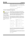
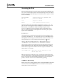
For the incremental encoder index pulse, we will use the position capture feature
to note where the index is. Set variable I912 to 1 if you have a high-true index
pulse, or to 9 if you have a low-true index pulse. (To see which it is, define
M119->X:$C000,14 and put M119 in the Watch window. If it is generally
0, you have a high-true pulse.) If you want to make sure the effective index
pulse is only 1 count wide, set I914 to 1, and I915 to the appropriate value for
your encoder.
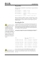
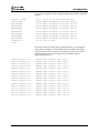
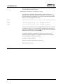
Now assign an M-variable to the encoder flag capture register:
M103->X:$C003,0,24,S
; Encoder 1 flag capture register
Add this to the Watch window. With the motor at rest, note the phase position
value in M171 and the encoder position register in M101. Write these values
down. Now turn/push the motor manually in the direction you plan to home the
machine until you see M103 change. The new value is the value of the encoder
register captured at the index pulse.
Subtract your starting M101 value from this new M103 value. Multiply the
difference by I170 and add this to the starting M171 value. The result is the
value we will write to the phase position register when we are settled at the
index to refine our initial rough phasing. Mathematically speaking:
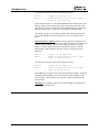
IndexPhasePos = I 170 * (IndexM 103 − StartM 101) + StartM 171
Alternately, in a technique that is easier mathematically but harder physically,
put M119 in the Watch window (or the index signal on an oscilloscope) and turn
the motor shaft until it stops on the index pulse. Read the M171 phase position
register value. This is the avlue we will write to the phase position register
when we are settled at the index to refine our initial rough phasing.
Using Hall-Effect Sensors for Phase Reference
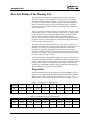
Hall-effect sensors, or their optical equivalents on a commutation encoder, for a
3-phase motor can be used for rough phasing on power-up without the need for
a phasing search move. This initial phasing provides reasonable torque, but it
will need to be corrected for top operation. Usually the correction is done when
the index pulse is reached, in the same technique that is described above for the
correction after a power-on phasing search move.
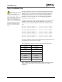
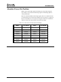
Hall-effect sensors usually map out 6 zones of 60oelec. each. In terms of
PMAC2's commutation cycle, the boundaries should be at 180o, -120o, -60o, 0o,
60o, and 120o. Typically a motor manufacturer will align the sensors to within a
few degrees of this, because these are the proper boundary points if all
commutation is done from the commutation sensors. If you are mounting the
hall-effect sensors yourself, you should take care to align the boundaries at these
points. The simplest way is to force the motor to the zero degree point with a
current offset (as shown above) and adjust the sensor while watching its outputs
to get a boundary as close as possible to this point.
5-8
PMAC2 User’s Manual – 15 March 1997