1
24
DTR.APC.APR.AL.01(ENG)
24,5 +1
19 -0.5
20
min. 14,5
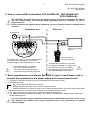
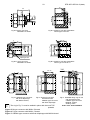
Fig.8a. G1/2-type connector
with G1/2" thread
Fig.8b. Socket for use with transmitters
with G1/2-type connector.
0,1 A
0.5
21,5
15 -0,2
min.10,5
A
90°
2,5
2,5
∅18,2+0,1
∅50
2,5
G1/2
∅32
∅21,3 -0,2
O-ring
15x2
G1/2A
10
∅18−0,05
Sealing: teflon
21,2 x 24,4 x 1,7
∅7
G1/2
1,25
∅6
∅4
G1/2
3
20,5-0,1
27-6kt.
Fig.8d. Weldable fitting ring for use with
transmitters with CG1/2 - type connector
Material – 316Lss
Order code Socket CG1/2
0,1 A
Fig.8c. CG1/2 -type connector
with flush diaphragm
with G1/2" thread,
Sealing: teflon
33,2 x 36,4 x 1,8
21.5
15-0,2
0.5
min .10,5
2,5
A
∅30,1+0,1
∅50
∅30,5 +0,1
90°
G1
2,5
∅40
O33.5-0,2
∅30 -0,05
G1"
O-ring
26x2
10
2,5
20.5
41-6kt.
Fig.8e. CG1-type connector
with flush diaphragm
with G1" thread,
Fig.8f. Weldable fitting ring for use with
transmitters with CG1 - type connector
Material – 316Lss
Order code Socket CG1
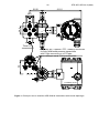
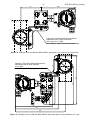
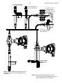
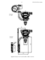
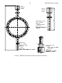
Figure 8. Process connections G1/2” and G1”.