1
DTR.APC.APR.ALW.03(ENG) APLISENS MANUFACTURE OF PRESSURE TRANSMITTERS AND CONTROL INSTRUMENTS USER’S MANUAL SMART PRESSURE TRANSMITTER type: APC-2000ALW SMART DIFFERENTIAL PRESSURE TRANSMITTER type: APR-2000ALW, APR-2200ALW, APR-2000GALW APR-2000ALW/L, APR-2200ALW/L SMART LEVEL PROBE type: APR-2000YALW SMART LEVEL TRANSMITTER APC-2000ALW/L… Edition C1 WARSAW AUGUST 2015 APLISENS S. A. 03-192 Warszawa, ul. Morelowa 7 tel. +48 22 814 07 77; fax +48 22 814 07 78 www.aplisens.pl, e-mail: [email protected] Symbols used Symbol i Description Warning to proceed strictly in accordance with the information contained in the documentation in order to ensure the safety and full functionality of the device. Information particularly useful during installation and operation of the device. Information particularly useful during installation and operation of an Ex device. Information on disposal of used equipment. BASIC REQUIREMENTS AND SAFE USE - The manufacturer will not be liable for damage resulting from incorrect installation, - - - - failure to maintain the device in a suitably functional condition, or use of the device other than for its intended purpose. Installation should be carried out by qualified personnel having the necessary authorisation to install electrical and pressure measuring devices. The installer is responsible for performing the installation in accordance with these instructions and with the electromagnetic compatibility and safety regulations and standards applicable to the type of installation. The device should be configured appropriately for the purpose for which it is to be used. Incorrect configuration may cause erroneous functioning, leading to damage to the device or an accident. In systems with pressure transmitters there exists, in case of leakage, a risk to personnel on the side where the medium is under pressure. All safety and protection requirements must be observed during installation, operation and inspections. If a device is not functioning correctly, disconnect it and send it for repair to the manufacturer or to a firm authorised by the manufacturer. In order to minimise the risk of malfunction and associated risks to personnel, the device is not to be installed or used in particularly hostile conditions, where the following risks occur: - possibility of mechanical impacts, excessive shocks and vibration; - excessive temperature fluctuation; - condensation of water vapour, dust, icing. Installation of intrinsically safe versions should be performed with particular care, in accordance with the regulations and standards applicable to that type of installation. Changes in the production of transmitters may precede a paper updating for the user. The current user manuals are available at http. www.aplisens.pl C1 1 DTR.APC.APR.ALW.03(ENG) CONTENTS I. APPENDIX Exd.ATEX ........................................................................................................................... 3 II. APPENDIX Exd.IECEx .......................................................................................................................... 7 III. APPENDIX Exi.ATEX ...........................................................................................................................10 IV. APPENDIX Exi.IECEx..........................................................................................................................14 V. APPENDIX MID ....................................................................................................................................17 VI. FEATURES, INSTALLATION AND MAINTENANCE OF TRANSMITTERS ...................................................23 1. INTRODUCTION ...................................................................................................................................23 2. USER MATERIALS...............................................................................................................................23 3. APPLICATIONS AND MAIN FEATURES..............................................................................................23 4. IDENTIFYING MARKS. ORDERING PROCEDURE ..............................................................................24 5. TECHNICAL DATA. ..............................................................................................................................24 5.1. APC..., APR... COMMON PARAMETERS .................................................................................................................... 24 5.2. APC-2000ALW MEASUREMENT RANGES AND METROLOGICAL PARAMETERS. ............................................................. 26 5.3. APR-2000ALW, APR-2000ALW/L, APR-2200ALW, APR-2200ALW/L MEASUREMENT RANGES AND METROLOGICAL PARAMETERS. .................................................................................................................................................... 27 5.4. APR–2000GALW, MEASUREMENT RANGES AND METROLOGICAL PARAMETERS. ............................................................. 29 5.5. APR–2000YALW. MEASUREMENT RANGES AND METROLOGICAL PARAMETERS............................................................... 29 5.6. APC–2000ALW/L…. MEASUREMENT RANGES AND METROLOGICAL PARAMETERS. .......................................................... 30 5.7. APC … APR … ENVIRONMENTAL PARAMETERS ....................................................................................................... 31 6. CONSTRUCTION .......................................................................................................................................32 7. 8. 9. 6.1. PRINCIPLE OF MEASUREMENT. ELECTRONIC SYSTEM CONSTRUCTION .......................................................................... 32 6.2. ENCLOSURE OF TRANSMITTERS. ................................................................................................................................ 32 PLACE OF INSTALLATION .................................................................................................................33 7.1. GENERAL RECOMMENDATIONS .................................................................................................................................. 33 7.2. LOW AMBIENT TEMPERATURE. .................................................................................................................................. 33 7.3. HIGH MEDIUM TEMPERATURE. .................................................................................................................................. 33 7.4. MECHANICAL VIBRATION SHOCKS. CORROSIVE MEDIA. ............................................................................................... 34 INSTALLATION AND MECHANICAL CONNECTIONS.........................................................................34 8.1. APC... INSTALLATION AND CONNECTIONS .................................................................................................................. 34 8.2. APR... INSTALLATION AND CONNECTIONS .................................................................................................................. 34 8.3. APR-2000GALW. INSTALLATION AND CONNECTIONS ................................................................................................ 34 8.4. APR-2000YALW. INSTALLATION AND CONNECTIONS ................................................................................................. 35 8.5. APC-2000ALW/L…. INSTALLATION AND CONNECTIONS............................................................................................. 35 ELECTRICAL CONNECTION ...............................................................................................................35 9.1. GENERAL RECOMMENDATIONS .................................................................................................................................. 35 9.2. ELECTRICAL CONNECTIONS FOR APC..., APR... ........................................................................................................ 36 9.3. PROTECTION FROM EXCESS VOLTAGE ........................................................................................................................ 36 9.4. EARTHING ................................................................................................................................................................ 36 10. SETTING AND REGULATION ..............................................................................................................36 10.1. TRANSMITTER RANGE, BASIC RANGE. DEFINITIONS .................................................................................................. 36 10.2. CONFIGURATION AND CALIBRATION ......................................................................................................................... 37 11. INSPECTIONS AND SPARE PARTS. ...................................................................................................46 11.1. PERIODIC SERVICE ................................................................................................................................................. 46 11.2. OTHER SERVICES ................................................................................................................................................... 46 11.3. CLEANING THE DIAPHRAGM SEAL, OVERLOADING DAMAGE ....................................................................................... 46 11.4. SPARE PARTS......................................................................................................................................................... 46 12. 13. 14. 15. 16. PACKING, STORAGE AND TRANSPORT. ..........................................................................................46 GUARANTEE. ......................................................................................................................................46 SCRAPPING, DISPOSAL. ....................................................................................................................47 ADDITIONAL INFORMATION...............................................................................................................47 FIGURES. .............................................................................................................................................47 FIG. 1. APC..., APR... TRANSMITTERS – BLOCK DIAGRAM. ................................................................................................. 47 FIG. 2. ELECTRICAL CONNECTIONS FOR APC..., APR... TRANSMITTERS: ............................................................................ 48 FIG. 3. APC-2000ALW SMART PRESSURE TRANSMITTER. ................................................................................................. 50 FIG. 4. APC..., APR.... DISPLAY ROTATION POSSIBILITY, CONFIGURATION BUTTONS. ........................................................... 51 FIG. 4A. “VERSION SC” FOR APC..., APR.... DISPLAY ROTATION POSSIBILITY, CONFIGURATION BUTTONS. ............................ 52 FIG. 5. BACK LIGHTING JUMPER VIEW AT TRANSMITTER ELECTRIC BOARD (UNIT DISPLAY BACK SIDE). .................................... 52 FIG. 6. M-TYPE CONNECTOR WITH M20X1.5 THREAD......................................................................................................... 53 FIG. 7. P-TYPE CONNECTOR WITH M20X1.5 THREAD. ........................................................................................................ 53 FIG. 8. CM30X2-TYPE CONNECTOR WITH FLUSH DIAPHRAGM WITH M30X2 THREAD............................................................. 53 FIG. 9. PROCESS CONNECTIONS G1/2” AND G1”. .............................................................................................................. 54 FIG. 10. APR-2000ALW DIFFERENTIAL PRESSURE TRANSMITTER WITH C TYPE VENTED COVERS. ....................................... 55 FIG. 11. APR-2000ALW DIFFERENTIAL PRESSURE TRANSMITTER WITH A SINGLE DIRECT DIAPHRAGM SEAL (EXAMPLE). ........ 55 C1 2 DTR.APC.APR.ALW.03(ENG) FIG. 12. EXAMPLE: HOW TO INSTALL THE APR-2200ALW TRANSMITTERS WITH REMOTE DIAPHRAGM................................... 56 FIG. 13. EXAMPLE: HOW TO INSTALL THE APR-2000ALW TRANSMITTER ON A VERTICAL OR HORIZONTAL PIPE...................... 57 FIG. 14. EXAMPLE: HOW TO INSTALL THE APR-2000ALW TRANSMITTER WITH A VALVE MANIFOLD TO A 2” PIPE..................... 57 FIG. 15. APR-2200ALW DIFFERENTIAL PRESSURE TRANSMITTER WITH TWO REMOTE DIAPHRAGM SEALS (EXAMPLES). ......... 58 FIG. 16. APR-2200ALW DIFFERENTIAL PRESSURE TRANSMITTER WITH DIRECT AND REMOTE DIAPHRAGM SEAL (EXAMPLES). 58 FIG. 17. EXAMPLE: HOW TO INSTALL THE APC..., APR... TRANSMITTER. ............................................................................. 59 FIG. 18. APR-2000GALW SMART DIFFERENTIAL PRESSURE TRANSMITTER FOR LOW RANGES. ............................................ 60 FIG. 19. APR–2000YALW SMART LEVEL PROBE FOR PRESSURE TANKS. ........................................................................... 61 FIG. 20. THE EXPLOSION - PROOF JOINTS OF APC..., APR... TRANSMITTERS. ..................................................................... 62 FIG. 21. HOW TO LEAD THE CASING OF APC..., APR... TRANSMITTERS. .............................................................................. 62 FIG. 22. APC–2000ALW/LSG… SMART LEVEL TRANSMITTERS. ....................................................................................... 63 FIG. 23. APC–2000ALW/LM & APC–2000ALW/LSP SMART PRESSURE OR LEVEL TRANSMITTERS. .................................. 64 FIG. 24. AN EXAMPLE OF THE DIFFERENTIAL PRESSURE TRANSMITTER APR-2200ALW/L.................................................... 65 FIG. 25. ADDITIONAL EQUIPMENT FOR FITTING OF PRESSURE TRANSMITTERS. ..................................................................... 66 C1 3 DTR.APC.APR.ALW.03(ENG) I. APPENDIX Exd.ATEX 1453 APC–2000ALW/XX PRESSURE TRANSMITTER, APR-2000ALW/XX, APR-2200ALW/XX, DIFFERENTIAL PRESSURE TRANSMITTERS, APR-2000YALW/XX LEVEL PROBE, Exd VERSION in accordance with ATEX directive 1. Introduction 1.1. This “Appendix Exd.ATEX” applies to transmitters of types APC-2000ALW/XX, APR-2000ALW/XX, APR-2200ALW/XX and APR-2000YALW/XX in Exd versions only, marked on the rating plate as shown in p.3 and denoted Exd in the Product Certificate. 1.2. The appendix contains supplementary information relating to the Exd (flame-proof) versions compatible with ATEX directive of mentioned transmitters. During installation and use of Exd transmitters, reference should be made to DTR.APC.APR.ALW.03(ENG) in conjunction with “Appendix Exd.ATEX”. 2. Use of APC…, APR… transmitters in dangers zones 2.1. The transmitters are produced in accordance with the requirements of the following standards: EN 60079-0:2012, EN 60079-1:2007, EN 60079-11:2012, EN 60079-26:2007, EN 60079-31:2009. 2.2. The transmitters may operate in areas where there is a risk of explosion, in accordance with the rating of the explosion protection design: I M2 Ex d ia I Mb (version with enclosure 1.4401(316)) II 1/2G Ex ia/d IIC T6/T5 Ga/Gb II 1/2D Ex ia/t IIIC T85ºC/T100ºC Da/Db KDB 08 ATEX 224X marking T6 and T85 applies to range -40ºC <Ta ≤ 45ºC marking T5 and T100 applies to range -40ºC <Ta ≤ 75ºC 2.3. Transmitter category and hazard areas. The category 1/2G, contained within the rating, means that the transmitter may be installed within a type 1 or 2 hazard zones. The APC…, APR… process connections may connect to a 0 zone type (see the diagram below for an example). Zone 0 Zone 1 or 2 Safe area Pressure transmitter or differential pressure transmitter 3. Identifying marks Flame-proof transmitters must have a rating plate containing the information specified in p.4 of DTR.APC.APR.ALW.03(ENG) and also at least the following: CE mark and number of notified unit; “Ex” mark, designation of explosion protection design, certificate number; Supply voltage; Designation of a process connection; Year of manufacture; Temperature use range. In place of XX letters in product rating plate will be written a pressure connection type symbols. C1 4 DTR.APC.APR.ALW.03(ENG) Appendix Exd.ATEX 4. User information Together with the ordered transmitters, the user will receive: a. Product Certificate; b. Declaration of conformity; c. Copy of certificate (on request); d. User’s Manual named: DTR.APC.APR.ALW.03(ENG) with Appendix Exd.ATEX. Items b), c), d) are available on www.aplisens.pl 5. Power supply and exploitation of transmitters. i i 5.1. The transmitter connecting should be made after introduction with present instruction content. Electrically transmitter should be connected according to scheme at p.6 Appendix Exd.ATEX. Transmitter electrical installation should be realised with engineering standard requirements. Electrical connections of transmitters in danger zone should be made by people who have indispensable knowledge and experience in this branch. Earth clamps must be used to earth transmitters. In the event that transmitters come in contact with structural metal parts or pipes which are connected to the equipotential bonding system, transmitters do not require to be earthed. 5.2. Transmitters should be supplied from DC electrical source with voltage max.45V from transformer feeders or other devices which have at least a strengthened isolation among primary and secondary windings in which don’t appear voltage higher than 250V. The duty of power supply installation with above mentioned requirements rests on user. 5.3. Transmitters can be used in ambient temperatures (Ta) between -40ºC < Ta ≤ 45ºC for class T6 or between -40ºC < Ta 75ºC for T5. 5.4. Transmitter sensor diaphragm should not be subject on damage during installation and exploitation. The diaphragm is made from 1.4404/1.4435 (316L) or Hastelloy thin foil and cannot be subject on medium which can entail its damage. 5.5. With regard on kind of casing material (light alloy with large aluminium content), the user is obliged to assure, that possibility of hitting casing does not step out in place of transmitter installation. 5.6. In transmitter casing are two holes to assembly of cable glands from thread M20x1.5 or 1/2 NPT. i 5.7. Normally transmitters are delivered without installed glands but with blank plugs (corks) in the second hole. The list of cable glands and plugs agreeable with production documentation and accepted by certificate station is specified in Table 1 and Table 2 (p.6 Appendix Exd.ATEX). Customer should install cable glands according to Tables 1 and plugs according to Tables 2 (if plugs aren’t installed) or other accordance with flame-proof standards. i 5.8. It is necessary to apply a shield cable or without shield cable with round cross-section in protection from elastomer, not moisture absorbing, for example: YKSLY 2 * 1, YnTKSYekw 1 * 2 * 1, LIYCY 2 * In case of need use cable with different structure, customer should co-ordinate this with transmitters’ manufacturer to choose intakes with cable diameter. 5.9. The general principles of connecting and the exploitation of transmitter in Exd realization should be compatible with principles and relating standards for Exd casing devices how in p.2.1 Appendix Exd.ATEX, in this including also: EN 600079-14, EN 60079-17. i 5.10. During service must be made a check of the tight fastening of covers and the cable glands and the fastening of the cable in the glands. The casing and supply line must be inspected for mechanical damage, and the transmitter rating plate for legibility. Periodic checks should also be made of the diaphragm, which should not carry signs of damage. During maintenance it is recommended that the threads of the covers be lubricated with non-acid vaseline. Because of the transmitter damage possibility, the ambient temperature should not be allowed to become higher than 80ºC, even when there is no explosion risk. C1 5 DTR.APC.APR.ALW.03(ENG) Appendix Exd.ATEX 6. The electrical connection way of transmitter’s series: APC-2000ALW/XX, APR-2000ALW/XX, APR-2200ALW/XX and APR-2000YALW/XX in Exd version Hazardous area Safe area + short-circuit( jumper) _ TEST + _ +SIGNAL Ro _ TEST Ex power supply see p.5. RD F1 F2 F3 PF RE F4 DEF GHI @%& JKL MNO PQR +/ STU VWX YZ# . 7 Fuse: In = 0,05A, Un = 250V according to EN 60127 F4 PV ABC 4 1 8 5 2 9 6 3 0 * Communicator Fig. 2. i In case of transmitter calibration outside danger zone is possible communicator connecting to <SIGNAL+> and <TEST+> terminals. Transmitter is furnished in communication resistor (RD = 240Ω), closed with jumper at <SIGNAL-> and <TEST-> terminals installed by manufacturer. RD resistor can be use then, when it is necessary to communicate with transmitter from its terminals and the load resistance (Ro) in current loop is lover then 240Ω. Than <SIGNAL-> and <TEST-> terminals have to be open. In danger zone don’t unscrew transmitter covers and don’t change the display position or its back lighting. Blocking cover method before unscrewing and plumbing possibility is shoved at Fig.20. It is not permitted to repair or otherwise interfere with the transmitter’s electrical circuits in any way. Damage estimation and repair possibility may be assessed by the manufacturer or another authorized party only. C1 6 DTR.APC.APR.ALW.03(ENG) Appendix Exd.ATEX Table 1. Permitted cable glands Type Producer Screw Feature Other marking No of certificate 501/423 HAWKE M20x1.5 Exd IIC dimension OS, O, A Baseefa 06 ATEX 0056X 501/421 HAWKE M20x1.5 Exd IIC dimension OS, O, A Baseefa 06 ATEX 0056X ICG 623 HAWKE M20x1.5 Exd IIC dimension OS, O, A Baseefa 06 ATEX 0058X 501/453 HAWKE M20x1.5 Exd IIC dimension OS, O, A Baseefa 06 ATEX 0056X * 501/453/RAC HAWKE M20x1.5 Exd IIC dimension OS, O, A Baseefa 06 ATEX 0056X * 501/453/Universal HAWKE M20x1.5 Exd IIC dimension OS, O, A Baseefa 06 ATEX 0057X * ICG 653 HAWKE M20x1.5 Exd IIC dimension OS, O, A Baseefa 06 ATEX 0058X * 8163/2-A2F STAHL M20x1.5 EXd IIC SIRA06ATEX1188X A2F, A2FRC, SS2K CMPProducts M20x1.5 Exd IIC SIRA06ATEX1097X E1FW, E1FX/Z, E2FW, E2FX/Z CMPProducts M20x1.5 Exd IIC SIRA06ATEX1097X * T3CDS, T3CDSPB CMPProducts M20x1.5 Exd IIC SIRA06ATEX1283X * PX2K, PXSS2K, PX2KX, PXB2KX CMPProducts M20x1.5 Exd IIC SIRA06ATEX1097X * Table 2. Permitted plugs Type Producer Screw Feature AGRO AG M20x1.5 Exd IIC 475 HAWKE M20x1.5 Exd IIC 477 HAWKE M20x1.5 Exd IIC Other marking No certificate *) for special cable only. Special conditions for safe use: - Permissible gap of joint marked in documentation by L4 is smaller than this was defined in norm EN 60079-1:2007 and cannot be greater than passed value on Fig. 20. - As the replacing elements, can be used only those specified in the descriptive documentation. C1 7 DTR.APC.APR.ALW.03(ENG) II. APPENDIX Exd.IECEx APC–2000ALW/XX PRESSURE TRANSMITTER, APR-2000ALW/XX, APR-2200ALW/XX, DIFFERENTIAL PRESSURE TRANSMITTERS, APR-2000YALW/XX LEVEL PROBE Exd VERSION in accordance with IECEx certificate 1. Introduction 1.1. This “Appendix Exd.IECEx” applies to transmitters of types APC-2000ALW/XX, APR-2000ALW/XX, APR-2200ALW/XX and APR-2000YALW/XX in Exd versions only, marked on the rating plate as shown in p.3 and denoted Exd in the Product Certificate. 1.2. The appendix contains supplementary information relating to the Exd (flame-proof) versions compatible with IECEx certificate of mentioned transmitters. During installation and use of Exd transmitters, reference should be made to DTR.APC.APR.ALW.03(ENG) in conjunction with “Appendix Exd.IECEx”. 2. Use of APC…, APR… transmitters in dangers zones 2.1. The transmitters are produced in accordance with the requirements of the following standards: IEC 60079-0:2007-10 ed.5, IEC 60079-1:2007-04 ed.6, IEC 60079-11:2006 ed.5, IEC 60079-31:2008 ed.1, IEC 60079-26:2006 ed.2. 2.2. The transmitters may operate in areas where there is a risk of explosion, in accordance with the rating of the explosion protection design: Ex d ia I Mb (version with enclosure 1.4401 (316)) Ex ia/d IIC T6/T5 Ga/Gb Ex ia/t IIIC T85ºC/T100ºC Da/Db IECEx KDB 14.0001X marking T6 and T85 applies to range -40ºC <Ta ≤ 45ºC marking T5 and T100 applies to range -40ºC <Ta ≤ 75ºC 2.3. Equipment protection level (EPL) and hazard areas. Equipment protection level (EPL) Ga/Gb (Da/Db), contained within the rating, means that the transmitter may be installed within a type 1 (21) or 2 (22) danger zone. Process connections can connect to zone 0 (20) (example shown below). Intrinsically safe transmitter marked Mb turn off if there is risk of an explosive atmosphere. Zone 0 Zone 1 or 2 Pressure transmitter or differential pressure transmitter Safe area C1 8 DTR.APC.APR.ALW.03(ENG) Appendix Exd.IECEx 3. Identifying marks Flame-proof transmitters must have a rating plate containing the information specified in p.4 of DTR.APC.APR.ALW.03(ENG) and also at least the following: Designation of explosion protection design, certificate number; Supply voltage; Designation of a process connection; Year of manufacture; Temperature use range. In place of XX letters in product rating plate will be written a pressure connection type symbols. 4. User information Together with the ordered transmitters, the user will receive: a. Product Certificate; b. Declaration of conformity (on request); c. Copy of certificate (on request); d. User’s Manual named: DTR.APC.APR.ALW.03(ENG) with Appendix Exd.IECEx. Items b), c), d) are available on www.aplisens.pl 5. Power supply and exploitation of transmitters i i 5.1. The transmitter connecting should be made after introduction with present instruction content. Electrically transmitter should be connected according to scheme at p.6 Appendix Exd.IECEx. Transmitter electrical installation should be realised with engineering standard requirements. Electrical connections of transmitters in danger zone should be made by people who have indispensable knowledge and experience in this branch. Earth clamps must be used to earth transmitters. In the event that transmitters come in contact with structural metal parts or pipes which are connected to the equipotential bonding system, transmitters do not require to be earthed. 5.2. Transmitters should be supplied from DC electrical source with voltage max.45V from transformer feeders or other devices which have at least a strengthened isolation among primary and secondary windings in which don’t appear voltage higher than 250V. The duty of power supply installation with above mentioned requirements rests on user. 5.3. Transmitters can be used in ambient temperatures (Ta) between -40ºC < Ta ≤ 45ºC for class T6 or between -40ºC < Ta 75ºC for T5. 5.4. Transmitter sensor diaphragm should not be subject on damage during installation and exploitation. The diaphragm is made from 1.4404/1.4435 (316L) or Hastelloy thin foil and cannot be subject on medium which can entail its damage. 5.5. With regard on kind of casing material (light alloy with large aluminium content), the user is obliged to assure, that possibility of hitting casing does not step out in place of transmitter installation. 5.6. In transmitter casing are two holes to assembly of cable glands from thread M20x1.5 or 1/2 NPT. i 5.7. Normally transmitters are delivered without installed glands but with blank plugs (corks) in the second hole. The list of cable glands and plugs agreeable with production documentation and accepted by certificate station is specified in Table 1 and Table 2 (p.6 Appendix Exd.ATEX). Customer should install cable glands according to Tables 1 and plugs according to Tables 2 (if plugs aren’t installed) or other accordance with flame-proof standards. i 5.8. It is necessary to apply a shield cable or without shield cable with round cross-section in protection from elastomer, not moisture absorbing, for example: YKSLY 2 * 1, YnTKSYekw 1 * 2 * 1, LIYCY 2 * In case of need use cable with different structure, customer should co-ordinate this with transmitters’ manufacturer to choose intakes with cable diameter. 5.9. The general principles of connecting and the exploitation of transmitter in Exd realization should be compatible with principles and relating standards for Exd casing devices how in p.2.1 Appendix Exd.IECEx, in this including also: IEC 600079-14, IEC 60079-17. i 5.10. During service must be made a check of the tight fastening of covers and the cable glands and the fastening of the cable in the glands. The casing and supply line must be inspected for mechanical damage, and the transmitter rating plate for legibility. Periodic checks should also be made of the diaphragm, which should not carry signs of damage. During maintenance it is recommended that the threads of the covers be lubricated with non-acid vaseline. C1 9 DTR.APC.APR.ALW.03(ENG) Appendix Exd.IECEx Because of the transmitter damage possibility, the ambient temperature should not be allowed to become higher than 80ºC, even when there is no explosion risk. It is not permitted to repair or otherwise interfere with the transmitter’s electrical circuits in any way. Damage estimation and repair possibility may be assessed by the manufacturer or another authorized party only. In danger zone don’t unscrew transmitter covers and don’t change the display position or its back lighting. 6. The electrical connection way of transmitter’s series: APC-2000ALW/XX, APR-2000ALW/XX, APR-2200ALW/XX and APR-2000YALW/XX in Exd version According to the p.6 DTR.APC.APR.ALW.03(ENG) Appendix Exd.ATEX. Special conditions for safe use: - Permissible gap of joint marked in documentation by L4 is smaller than this was defined in norm IEC 60079-1:2006 ed.5 and cannot be greater than passed value on Fig. 20. - As the replacing elements, can be used only those specified in the descriptive documentation. C1 10 DTR.APC.APR.ALW.03(ENG) III. APPENDIX Exi.ATEX APC–2000ALW PRESSURE TRANSMITTER, APR–2000ALW, APR–2200ALW, APR–2000GALW, APR-2000ALW/L, APR-2200ALW/L DIFFERENTIAL PRESSURE TRANSMITTERS, APR–2000YALW LEVEL PROBE, APC–2000ALW/L LEVEL TANSMITTER Ex VERSION in accordance with ATEX directive 1453 1. Introduction 1.1. This “Appendix Exi.ATEX” applies to transmitters of types APC–2000ALW, APR–2000ALW, APR–2200ALW, APR–2000GALW, APC–2000ALW/L, APR-2000ALW/L, APR-2200ALW/L and APR–2000YALW in Ex versions only, marked on the rating plate as shown in p.2.2 and denoted Ex in the Product Certificate. 1.2. The appendix contains supplementary information relating to the Ex versions compatible with ATEX directive of mentioned transmitters. During installation and use of Ex transmitters, reference should be made to DTR.APC.APR.ALW.03(ENG) in conjunction with “Appendix Exi.ATEX”. 2. Use of APC…, APR… transmitters in danger zones 2.1. The transmitters are produced in accordance with the requirements of the following standards: EN 60079-0:2012, EN 60079-26:2007, EN 60079-11:2012, EN 50303:2000. 2.2. The transmitters may operate in areas where there is a risk of explosion, in accordance with the rating of the explosion protection design: II II II I 1/2G Ex ia IIC T5/T6 Ga/Gb 1/2G Ex ia IIB T5/T6 Ga/Gb 1D Ex ia IIIC T105ºC Da M1 Ex ia I Ma (version with Teflon-shielded cable) (version with enclosure 1.4401 (316)) FTZÚ 08 ATEX 0020X For “Version SC” and “Version SC, SA”: II II II I 1/2G Ex ia IIC T4/T5 Ga/Gb 1/2G Ex ia IIB T4/T5 Ga/Gb 1D Ex ia IIIC T105ºC Da M1 Ex ia I Ma (version with Teflon-shielded cable) (version with enclosure 1.4401 (316)) FTZÚ 08 ATEX 0020X 2.3. Transmitter category and hazard areas The category 1/2G, contained within the rating, means that the transmitter may be installed within a type 1 or 2 hazard zones. The APC…, APR… process connections may connect to a 0 zone type (see the diagram below for an example). Safe area EP COVER T I G L WH E E IV KE Safe area N Zone 1 or 2 HT CI RCU I TS A Zone 0 transmitter Pressure transmitter or differential pressure transmitter Zone 1 or 2 Zone 0 C1 11 DTR.APC.APR.ALW.03(ENG) Appendix Exi.ATEX 3. Identifying marks Intrinsically safe transmitters must have a rating plate containing the information specified in paragraph 4 of DTR.APC.APR.ALW.03(ENG) and also at least the following: CE mark and number of notified unit: mark; Designation of explosion protection design, certificate number; Values of parameters such as: Ui, Ii, Pi, Ci, Li; Year of manufacture; Text: "Version SA", "Version SC, SA" - separate power supply for transmitters with surge arresters. Power supply must be separate to earth. 4. User information Together with the ordered transmitters, the user will receive: a) Product Certificate; b) Declaration of conformity; c) Copy of certificate (on request); d) User’s Manual named: DTR.APC.APR.ALW.03(ENG) with Appendix Exi.ATEX. Items b), c), d) are available on www.aplisens.pl 5. Permitted input parameters (based on data from the FTZÚ 08 ATEX 0020X certificate, and certification documentation) The transmitters should be powered via the associated power feeding and measurement devices provided with the relevant intrinsic-safe certificates. The parameters of their outputs to the danger zone should not exceed the limit power supply parameters for the below specified transmitters. Note: Transmitters marked on the nameplate as "Version SC" or "Version SC, SA" have other input parameters see section 5.1, 5.3, 5.5 of Appendix Exi.ATEX. 5.1. For power supply with an linear output characteristic in „Version SC" or “Version SC, SA” version Ui = 28V Ii = 0.1A Pi = 0.7W -40ºC Ta 70ºC and T5 5.2. For power supply with a linear output characteristic Ui = 30V Ii = 0.1A Pi = 0.75W -40ºC Ta 40ºC and T6, -40ºC Ta 80ºC and T5 Power supply with a linear characteristic may be e.g. a typical barrier with parameters Uo = 28V Io = 0.093A Rw = 300. Ii Rw ID transmitter Io Uo Fig.1. Power supply from a source with linear characteristic. Zasada zasilania o charakterystyce liniowej (Radwanice) 5.3. For power supply with a trapezial output characteristic in „Version SC" or “Version SC, SA” Ui = 24V Ii = 50mA Pi = 0.7W -40ºC Ta 80ºC and T5 5.4. For power supply with a trapezial output characteristic Ui = 24V Ii = 50mA Pi = 0.7W -40ºC Ta 80ºC and T5 Example of power supply from a source with trapezial characteristic (see Fig. 2). transmitter Ii Io Ui Rw Uo ID Uq Fig. 2. Power supply from a source with trapezial characteristic. C1 12 If Uo < DTR.APC.APR.ALW.03(ENG) Appendix Exi.ATEX Uq 2 then parameters Uq, Io, Po are interrelated as follows: Uo(Uq – Uo) 4Po Uq Uq = , Rw = , Po = for Uo ≤ 1/2Uq Io Io Rw 5.5. For power supply with a rectangular output characteristic in „Version SC" or “Version SC, SA” Ui = 24V Ii = 25mA Pi = 0.6W -40ºC Ta 80ºC and T5 Ui = 24V Ii = 50mA Pi = 1.2W -40ºC Ta 80ºC and T4 5.6. For power supply with a rectangular output characteristic Ui = 24V Ii = 25mA Pi = 0.6W -40ºC Ta 40ºC and T6, -40ºC Ta 80ºC and T5 Ui = 24V Ii = 50mA Pi = 1.2W -40ºC Ta 70ºC and T5, The supply of power from a source with a rectangular characteristic means that the voltage of the Ex power supply remains constant until current limitation activates. The protection level of power supplies with a rectangular characteristic is normally “ib”. The transmitter powered from such a supply is also an Ex device with protection level “ib”. Example of practical provision of power supply. – use a stabilized power supply with Uo=24V with protection level „ib” and current limited to Io=25mA. 5.4. Input inductance and capacity Ci=2.5nF, Li=18µH 5.6. Supply voltage min.: 10.5VDC For „Version SC” or „Version SC, SA”: 13.5V DC 5.7. Load resistance: - from 28V linear supply Ro max [Ω] = 28V – 10.5V** – (300Ω* · 0.0225A) 0.0225A - from a source with trapezial or rectangular characteristic supply Ro max [Ω] = Usup. – 10.5V ** 0.0225A *) barrier resistance; **) 13.5V DC for “Version SC” and “Version SC, SA”. C1 13 DTR.APC.APR.ALW.03(ENG) Appendix Exi.ATEX 6. How to connect Ex transmitters APC…, APR… The transmitter and other devices in the measuring loop should be connected in accordance with the intrinsic-safety and explosion-safety regulations and the conditions for use in dangerous areas. Failure to observe the intrinsic-safety regulations can cause explosion and the resulting hazard to people. Hazardous area Safe area Ex-Milliammeter + Jumper mA _ TEST + Ro _ TEST _ +SIGNAL a Ex power supply see p.5. RD F1 F2 F3 PF RE F4 PV F4 ABC DEF GHI @%& JKL MNO PQR +/ STU VWX YZ# . 7 4 1 8 5 2 9 6 3 0 * Aplisens KAP-03Ex Communicator To measure the current in the transmitter without disconnecting the signalling circuit, connect a milliammeter to transmitter terminals TEST+, TEST-. In hazardous areas, connections to the control terminals must be made using only instruments which are permitted to be used in such areas. i The transmitter is equipped in additional communication resistor RD = 240Ω. During normal operation terminals <SIGNAL –> and <TEST –> are shorted. RD resistor is used when you wish to communicate with the transmitter locally (from its terminals) and Ro < 240. Terminals <SIGNAL –> and <TEST –> must be opened. i If the temperature of the medium exceeds Ta, then suitable separators such as membrane separators or P-type siphon tubes must be used. Transmitter working temperature (Tp) must conform to Tp≤Ta. Special conditions for safe use: Version of transmitter with surge arrester, marked on the plate "Version SA", "Version SC, SA" does not meet the requirements of Section 10.3 of the EN 60079-11:2012 (500Vrms). This must be taken into account when installing the equipment. Transmitter electrical installation should be realised with engineering standard requirements. It is not allowed to repair or otherwise interfere with the transmitter’s electrical circuits in any way. Damage and possible repair may be assessed only by the manufacturer or another authorized party. C1 14 DTR.APC.APR.ALW.03(ENG) IV. APPENDIX Exi.IECEx APC–2000ALW PRESSURE TRANSMITTER, APR–2000ALW, APR–2200ALW, APR–2000GALW, APR-2000ALW/L, APR-2200ALW/L DIFFERENTIAL PRESSURE TRANSMITTERS, APR–2000YALW LEVEL PROBE, APC–2000ALW/L LEVEL TANSMITTER Ex VERSION in accordance with IECEx certificate 1. Introduction 1.1. This “Appendix Exi.IECEx” applies to transmitters of types APC–2000ALW, APR–2000ALW, APR–2200ALW, APR–2000GALW, APC–2000ALW/L, APR-2000ALW/L, APR-2200ALW/L and APR–2000YALW in Ex versions only, marked on the rating plate as shown in p.2.2 and denoted Ex in the Product Certificate. 1.2. The appendix contains supplementary information relating to the Ex versions compatible with IECEX certificate of mentioned transmitters. During installation and use of Ex transmitters, reference should be made to DTR.APC.APR.ALW.03(ENG) in conjunction with “Appendix Exi.IECEx”. 2. Use of APC…, APR… transmitters in danger zones 2.1. The transmitters are produced in accordance with the requirements of the following standards: IEC 60079-0:2011 ed. 6.0, IEC 60079-26:2006 ed. 2.0, IEC 60079-11:2011 ed. 6.0. 2.2. The transmitters may operate in areas where there is a risk of explosion, in accordance with the rating of the explosion protection design: Ex Ex Ex Ex ia ia ia ia IIC T5/T6 Ga/Gb IIB T5/T6 Ga/Gb IIIC T105ºC Da I Ma (version with Teflon-shielded cable) (version with enclosure 1.4401 (316)) IECEx FTZÚ 14.0026X 2.3. Equipment protection level (EPL) and hazard areas. Equipment protection level (EPL) Ga/Gb, contained within the rating, means that the transmitter may be installed within a type 1 or 2 danger zone. Process connections can connect to zone 0 (example shown below). Safe area EP COVER T I G L WH E E IV KE Safe area N Zone 1 or 2 HT Zone 0 CI RCU I TS A transmitter Pressure transmitter or differential pressure transmitter Zone 1 or 2 Zone 0 3. Identifying marks Intrinsically safe transmitters must have a rating plate containing the information specified in paragraph 4 of DTR.APC.APR.ALW.03(ENG) and also at least the following: Designation of explosion protection design, certificate number; Values of parameters such as: Ui, Ii, Pi, Ci, Li; Year of manufacture; Text: "Version SA" - separate power supply for transmitters with surge arresters. Power supply must be separate to earth. C1 15 DTR.APC.APR.ALW.03(ENG) Appendix Exi.IECEx 4. User information Together with the ordered transmitters, the user will receive: a) Product Certificate; b) Declaration of conformity (on request); c) Copy of certificate (on request); d) User’s Manual named: DTR.APC.APR.ALW.03(ENG) with Appendix Exi.IECEx. Items b), c), d) are available on www.aplisens.pl 5. Permitted input parameters (based on data from the IECEx FTZÚ 14.0026X certificate, and certification documentation) The transmitters should be powered via the associated power feeding and measurement devices provided with the relevant intrinsic-safe certificates. The parameters of their outputs to the danger zone should not exceed the limit power supply parameters for the below specified transmitters. 5.1. For power supply with a linear output characteristic Ui = 30V Ii = 0.1A Pi = 0.75W -40ºC Ta 40ºC and T6, -40ºC Ta 80ºC and T5 Power supply with a linear characteristic may be e.g. a typical barrier with parameters Uo = 28V Io = 0.093A Rw = 300. Ii Rw ID transmitter Io Uo Fig.1. Power supply from a source with linear characteristic. Zasada zasilania o charakterystyce liniowej (Radwanice) 5.2. For power supply with a trapezial output characteristic Ui = 24V Ii = 50mA Pi = 0.7W -40ºC Ta 80ºC and T5 Example of power supply from a source with trapezial characteristic (see Fig. 2). transmitter Ii Io Ui Rw Uo ID Uq Fig. 2. Power supply from a source with trapezial characteristic. Uq If Uo < 2 then parameters Uq, Io, Po are interrelated as follows: Uo(Uq – Uo) 4Po Uq Uq = , Rw = , Po = for Uo ≤ 1/2Uq Io Io Rw 5.3. For power supply with a rectangular output characteristic Ui = 24V Ii = 25mA Pi = 0.6W -40ºC Ta 40ºC and T6, -40ºC Ta 80ºC and T5 Ui = 24V Ii = 50mA Pi = 1.2W -40ºC Ta 70ºC and T5, The supply of power from a source with a rectangular characteristic means that the voltage of the Ex power supply remains constant until current limitation activates. The protection level of power supplies with a rectangular characteristic is normally “ib”. The transmitter powered from such a supply is also an Ex device with protection level “ib”. Example of practical provision of power supply. – use a stabilized power supply with Uo=24V with protection level „ib” and current limited to Io=25mA. 5.4. Input inductance and capacity Ci=2.5nF, Li=18µH 5.6. Supply voltage min.: 10.5VDC C1 16 DTR.APC.APR.ALW.03(ENG) Appendix Exi.IECEx 5.7. Load resistance: - from 28V linear supply Ro max [Ω] = 28V – 10.5V – (300Ω* · 0.0225A) 0.0225A - from a source with trapezial or rectangular characteristic supply Ro max [Ω] = Usup. – 10.5V 0.0225A *) barrier resistance. 6. How to connect Ex transmitters APC…, APR… According to the p.6 DTR.APC.APR.ALW.03(ENG) Appendix Exi.ATEX. Special conditions for safe use: Version of transmitter with surge arrester, marked on the plate "Version SA" does not meet the requirements of Section 10.3 of IEC 60079-11:2011 (500Vrms). This must be taken into account when installing the equipment. Transmitter electrical installation should be realised with engineering standard requirements. It is not allowed to repair or otherwise interfere with the transmitter’s electrical circuits in any way. Damage and possible repair may be assessed only by the manufacturer or another authorized party. C1 17 DTR.APC.APR.ALW.03(ENG) Appendix MID V. APPENDIX MID 1453 1. APC-2000ALW PRESSURE TRANSMITTERS, GAUGE and ABSOLUTE, APPLICATIONS ACCORDANCE IN EN 12405-1:2005+A2:2010 STANDARD INTRODUCTION 1.1. The "MID Appendix" applies only to the APC-2000ALW absolute / relative transmitters applications where they are as instruments for use in/as measuring devices (MI-002 gas) in accordance with the EN 12405-1:2005 +A2:2010 standard harmonized to Measuring Instruments Directive (MID) 2004/22, and the OIML R140:2007 recommendations. 1.2. The appendix contains the transmitters data to realizations them to uses in metrology. During the installation and use of pressure transmitters in the MID version, is necessary to use the DTR.APC.APR.ALW.03(ENG) together with MID Appendix - in situations of ambiguous interpretations of text connected with installation and service of transmitters made according to MID version the final resolution is as written in MID Appendix. 2. APC-2000ALW transmitters in MID version. Inscriptions APC-2000ALW transmitters made for MID applications have a rating plates on which there are at least given below information: APLISENS S. A. 03-192 WARSZAWA ul. Morelowa 7 T. +48 22 814 07 77 F. +48 22 814 07 78 POLAND www.aplisens.pl www.aplisens.pl APLISENS SA - Produkcja Przemysłowej Aparatury Pomiarowej i Elementów Automatyki smart pressure transmitter INTELIGENTNY PRZETWORNIK CIŚNIENIA TYP: APC-2000ALW/ XX type APC-2000ALW / XX > p = - - - ... - - - MPa > p max = - - - - MPa > t amb, min = -25 o C > U supl. = >I output = t amb, max = 55 o C --- ... --- V DC 4...20mA DC + HART Ser.-No - - - - - - - - Year of production - - - - - - 03-192 WARSZAWA ul. Morelowa 7 tel. 022 814 07 77 fax 022 814 07 78 Zakres pomiarowy: - - - ... - - - MPa Ciśnienie max: - - - MPa Zakres temp.: t amb, min = -25 o C t amb, max = 55 o C Zasilanie: Sygnał wyjściowy: --- ... --- V DC 4...20mA + HART Numer seryjny: - - - - - - - - IP 66 Mat. - - - - - - version in accordance with EN 12405-1+A2:2010 Part's Certificate No. -- -- --- -- -- -- -ATEX cerificates designation: Exi or Exd Rok produkcji: - - - - - IP 66 Mat. - - - - - - wersja zgodna z PN- EN 12405-1+A2:2010 Nr certyfikatu części -- -- --- -- -- -- -oznaczenia certyfikatów: Exi z parametrami: Ui, Ii, Li, Ci lub Exd An APC-2000ALW transmitter for MID applications distinguishes from the other applications by information at rating plate that is made in accordance with EN 12405-1:2005+A2:2010 and is written a Number of Parts Certificate. In place of the XX in the transmitter type is given the type of connection to the pressure installation. Units of pressure on the rating plate of bars and MPa are used interchangeably. 3. APC-2000ALW transmitters in MID version. Application 3.1. Pressure Transmitters Series APC-2000ALW, version in accordance with EN 12405-1:2005+A2:2010, are provided for use in gas volume conversion devices of type 2, equipped with a backup electrical power source (battery, UPS) for gaseous fuels first and second families according to EN 437. 3.2. Using transmitters in the danger zones. All APC-2000ALW transmitters in version according to EN 12405-1:2005+A2:2010 are Intrinsically Safe (Exi) or Flame-proof (Exd), and as such are made in accordance with the standards set out in Exi or Exd Annex. Transmitters in the version in accordance to EN 12405-1:2005+A2:2010 can operate in hazardous areas in accordance to the designation of explosin-proof construction. Specific parameters of the Exi or Exd application, according to ATEX, with certificate numbers are given on the nameplate of the transmitter. APC-2000ALW intrinisically safe pressure transmitters in MID version have the following input parameters: Ci = 30nF, Li = 0.75mH, -25ºC ≤ Ta ≤ 55ºC. Other parameters are in accordance with “Exi.ATEX Appendix”. APC-2000ALW flame-proof pressure transmitters in MID version have the temperature range: -25ºC ≤ Ta ≤ 55ºC, other parameters are in accordance with “Exd.ATEX Appendix”. During installation and use of pressure transmitters in the MID version to be followed these parameters and other data contained in "Appendix Exi.ATEX" or "Appendix Exd.ATEX" to Manual. C1 18 4. DTR.APC.APR.ALW.03(ENG) Appendix MID List of completeness Together with APC-2000ALW transmitter user receives: a) Product Certificate which is also a warranty; b) Declaration of Conformity - on request; c) User's Manual; d) Copies of certificates - on request; e) Calibration certificate - on request. Items: b, c, d can be found at: www.aplisens.pl 5. APC-2000ALW for MID applications. Technical parameters Transmitter supply (Usup) 13.5* ÷ 28V DC for Exi versions 13.5* ÷45V DC for Exd versions 4÷20mA + HART -25 ÷ 55ºC 10 ÷ 98% with condensation IP 66 Output signal Ambient temperature Relative humidity Case protection ingress (according to EN 60529) *) Backlight setting of indicates increases the minimum supply voltage by 3V. Display backlight is switched on by the manufacturer at the order of the customer. In standard transmitters the backlight is turned off. i i For the needs of clearing, in accordance with Directive 2004/22/EC, should be used one of the two metrological checked transmitter output signals: digital HART signal or loop current signal. Ingress case protection for gaseous fuels 1 and 2 family in accordance with EN 437 provides a design of transmitter case and cable glands and plugs with seals of the HNBR, or TPE. In the situation of its own cable glands and plugs you should use components dedicated to Ex zones, to ensure: temperature, resistance to fuel gas families 1 and 2 and the above degree of protection. Can be used cable glands with sealants such as TPE's for example: EX1100.20.110 AGRO. 5.1. Transmitters environmental parameters in the MID version Products in this embodiment meets the following requirements; criteria by EN 12405-1:2005+A2:2010. 5.1.1. Electromagnetic Compatibility, immunity 5.1.2 Short drops in electrical supply EN 61000-4-29 Electrostatic Discharge (ESD): Level 1 EN 61000-4-2 Level 4, Contact: ±8kV Air: ±15kV Criterion A, Conducted Radio Frequency: EN 61000-4-6 Level 3 0.15… 80MHz - 10V Criterion A, Radiated Electromagnetic Field: EN 61000-4-3 Level 3 80 … 1 000MHz – 10V/m 1 … 2.700GHz – 1V/m Criterion A, Magnetic Field: EN 61 000-4-8 Level 4 Electrical Fast Transient (Burst): EN 61000-4-4 ± 2kV, I/O Electrical Slow Transient (Surges): EN 61000-4-5 Level 3 5.1.3. Climatic Immunity The transmitters can be installed in different climatic conditions (see p.7 DTR.APC.APR.ALW.03(ENG)) in environments of varying humidity, also in areas of water vapour condensation. Environment temperature: EN 60068-2-1, EN 60068-2-2, EN60068-3-1 hot: T = 55ºC, RH = max 55% cold: T = -25ºC, Humid Permanent Heat: EN60068-2-78 T=55ºC, RH=93%, 96h Damp Heat Cycle: EN 60068-2-30 (T = 22 ÷ 55ºC, RH = 80 ÷ 100%, 24h)x2 5.1.4. Mechanical Immunity Shocks: EN 60068-2-31, level 2 Vibrations in a wide band: EN 60068-2-64, test Fh, level 2 C1 19 DTR.APC.APR.ALW.03(ENG) Appendix MID 5.2. Connectors to pressure installation Connecting your pressure install with a transmitter should be made in accordance with the requirements for an installation using the transmitter connector. Transmitters in the MID version are equipped with one of the following types of Aplisens pressure ports: M, P, G1/2 G1/4, GP, R1/2, 1/2NPT (see p.5.2.4 DTR.APC.APR.ALW.03(ENG)). Pressure connection type, which designation given is the type of transmitter, the purchaser should agree with the manufacturer. Transmitters in the MID version do not provide connections to the diaphragm seals. 5.3. APC-2000ALW for MID applications. Electrical connections to the transmitter jumper gas-volume FOR HART OUTPUT SIGNAL JUMPER MUST BE REMOWED WHEN Ro<240 + Ro 4÷20 mA + Hart + - 240 -TEST +TEST _ SIGNAL conversion device with DC supplier In measuring systems according to EN 12405-1:2005+A2:2010 APC-2000ALW transmitters in MID version connecting to measuring install is always a two wire. For the connection of power and signal receiving terminals <SIGNAL+> and <SIGNAL-> of transmitter should be used with the polarization behavior - < + > to <SIGNAL+>; < - > to <SIGNAL->. Terminals < TEST +> and < TEST - > of transmitter in the metrological applications are not used. The cable shield should be connected one-sidedly to grounding - the manufacturer recommends connect the shield to the converter installation grounding point. The way of APC-2000ALW transmitter connecting to measurement installation in MID applications is shown in Figure 1a. Fig. 1a. APC-2000ALW for MID application. Connecting diagram of transmitter to powering and measuring installation. + KE 4÷20 mA + HART conversion device + EP Ro L E E IV shield N CI RCU I TS A L conversion device with DC supplier E E IV _ N KE 4÷20 mA + HART EP Fig. 1b. APC-2000ALW pressure transmitter for MID application. Recommended by manufacter way of earthing to the measuring system. _ with DC supplier CI RCU I TS A C1 20 DTR.APC.APR.ALW.03(ENG) Appendix MID For electrical connection should be use twisted pair cable; shielded or not shielded, flexible, with diameter 5mm ≤ ≤ 9mm, complies to ATEX standards. Example of the type of cable is shown below. Producer Technokabel LAPPKABEL Type (not shielded) IB-YSLY 2x0.75 * ÖLFLEX® EB 2X1 (nr art. 0012440) Type (shielded) IB-YSLCY 2x0.75 ÖLFLEX® EB CY 2X1 (nr art. 0012650) *) Maximum conductors cross-section: 2.5mm. Grounding to the transmitter should be performed according to the gas-volume conversion device documentation. To transmitter grounding should be used external earthing terminal if grounding by pressure connector is not enough. An exemplary method of grounding of pressure measuring system is shown in Figure 1b. 5.4. Cable entries (glands). Transmitters in the MID version are equipped with cable entries which meet the ATEX requirements (see Appendix Exi.ATEX and Appendix Exd.ATEX) and the requirements of EN 12405-1:2005+A2:2010. In order to facilitate the adaptation of transmitter installation parameters for user-specific installation requirements, in agreement with the user, transmitters can be supplied without glands and plugs. Then user must verify and approve applied own cable inlets and plugs which will use for compliance with the requirements of ATEX, IP and EN 12405-1:2005+A2:2010. 6. APC-2000ALW for MID application. Measurement ranges and metrological parameters 6.1. APC-2000ALW for MID application. Measurement ranges. Overpressure Range Absolute/gauge Maximum pressure 30 … 100 bar * absolute 100 bar 2 … 20 bar absolute 20 bar 2 … 20 bar gauge 20 bar 0.9 … 7 bar absolute 7 bar 0.9 … 7 bar gauge 7 bar *) According to EN 12405-1:2005+A2:2010 pressure units: bar and MPa can be used interchangeably. Measuring range of transmitters is setting by the manufacturer. Blocking against changes in the transmitter settings can be made as follows: systemically, by HART System, activated by a configuration program (Report 2) and protected by password; "spec MID locking" done with local buttons on the transmitter with a local menu (command MID_WP). For pressure transmitters complying to MID Parts Certificate, a manufacturer's standard "spec locking" is activated, but in agreement with the customer transmitters are not blocked and then the locking should be on by manufacturer of conversion devices. Local buttons are protected by a screw display cover, which is sealed. When "spec MID locking" is done can change only certain parameters of the transmitters, ie: HART transmitter address and the time constant, and can be made additional entries identifying the transmitter associated with its place of installation. The proceedings relating to the sealing set out in p. 8. i The pressure transmitter, as a part of the gas conversion of type 2, in accordance with the requirements of the MID Directive must be protected against unauthorized manipulation by its producer or manufacturer of the gas volume converter. Sealing of the transmitters is done by its manufacturer or, by agreement with the customer, they may not be sealed, then sealing should be made by manufacturer of gas volume conversion. 6.2. Measurement error (according to EN12405-1:2005+A2:2010) in relation to the measured value: at the rated temperature range (-25 ÷ 55ºC) ≤ 0.5% at reference conditions ≤ 0.2% 6.3. Long term stability / 5 years ≤ 0.5% The manufacturer recommends a vertical mount transmitter APC-2000ALW during the pressure measurements in MID applications. C1 21 DTR.APC.APR.ALW.03(ENG) Appendix MID 7. APC-2000ALW in MID application. Electronic display Electronic indicating device (display), built-in the APC-2000ALW transmitters, are not controlled metrologically and as such cannot be used for clearing in accordance with EN12405-1:2005+A2:2010. 8. APC-2000ALW in MID application. Protection against unauthorized manipulation 8.1. Blocking by the transmitters manufacturer. Access to the local configuration buttons and to the transmitter internal components is blocked by the sealing of the display cover and a measuring head locking screw to the housing of the transmitter. The transmitter rated plates are made of materials self-destructive during detachment, or alternative used metal rated plates have one of the screws sealed to the casing. Access “spec MID locking” protects against unauthorized interference to transmitters from a HART system. APC-2000ALW series transmitter manufacturer is using with a plastic seal in its MID realization. Change of the "spec MID locking” status ("ON" or "OFF") is possible after removing of the manufacturer sealing from the local buttons side cover only. 8.2. Blocking by the gas volume conversion manufacturer. Turn on the "spec MID locking" with local buttons using local menu of transmitter (p.10.2.5.2 DTR.APC.APR.ALW.03(ENG), MID_WP – “ON”). Put the seals of the gas volume conversion producer on the cover, screw of a sensor head and a label if it is metal made. Places of seals application is shown by the arrows at Fig. 1c. Seal should be made in accordance with the documentation of gas volume conversions in the place/country their use. KE COV E R T I G L RCU I T S A CI COV E R T I G WH EN L E IV EP HT KE producer,s seal CI RCU I T S A user's seal Fig 1c. APC-2000ALW in MID application. Sealed up transmitter. WH EN E IV EP HT FIELD TERMINALS blocking of cover plates against unscrewing C1 22 DTR.APC.APR.ALW.03(ENG) Appendix MID 9. APC-2000ALW in MID application. Alarms Pressure transmitters in MID version alarm exceeding of the limits of measuring ranges (lower and upper) by flag in the output signal HART, and information, respectively "o u E r" or "u n d E r" in place of the first process variable on a transmitter display. Other alarms work as at p.10.3 this User Manual DTR.APC.APR.ALW.03(ENG). 10. Verify of the pressure transmitter in its workplace To verify the correct functioning of the transmitter at its workplace should be used a HART system diagnostic tool implemented to transmitter. For this purpose is need: converter HART / RS-232 or other for example HART/USB/Bluetooth Converter; PC with Windows XP or higher, with at least 512 MB of RAM; Report 2 APLISENS software. A computer with a converter must be connected to the transmitter as shown in Figure 2a or 2c for the load resistance Ro <240 , see User's Manual DTR.APC.APR.ALW.03(ENG) p.16. Drawings. After starting Report 2 program read data from the transmitter. Installation parameters and current parameters of the transmitter are recorded in the tabs of the Report 2. And so in: Identification tab - read the identity data of the transmitter; Basic parameters tab - check the measuring range, pressure unit and time constant; Process Variables tab - check the current parameters of the transmitter measuring; Write protection tab - check the setting of current lock before entries; Transmitter Status tab - check the current status of the transmitter, its analog and digital outputs status with the marked exceeded errors of measuring range, or errors of particular blocks of the transmitter if they would existed. Transmitter verify in the workplace should make a worker who is trained in the handling of measuring electrical installations in explosive environments. 11. APC-2000ALW in MID application. Repair, calibration Transmitters repair should be performed by the manufacturer, or the manufacturer's authorized repair shops. The procedures of handling after transmitters repairs should be in accordance to the provisions of the country where transmitters are operating. C1 23 DTR.APC.APR.ALW.03(ENG) VI. FEATURES, INSTALLATION AND MAINTENANCE OF TRANSMITTERS 1. INTRODUCTION 1.1. This Manual is intended for users of APC-2000ALW smart pressure transmitters, APR-2000ALW, APR-2200ALW, APR-2000GALW, APR-2000ALW/L, APR-2200ALW/L smart differential pressure transmitters, APR-2000YALW smart level probe, APC-2000ALW/L smart level transmitter and their intrinsic-safety versions, containing the data and guidelines necessary to understand the functioning of the transmitters and how to operate them. It includes essential recommendations concerning installation and use, as well as emergency procedures. The parameters and information specified for transmitters identified here as APC..., APR... also apply to transmitters: APC-2000ALW, APR-2000ALW, APR-2200ALW, APR-2000ALW/L, APR-2200ALW/L, APR-2000GALW, APR-2000YALW, APC-2000ALW/L and their explosion-proof versions, as well as all the variations differing by the type of the process terminals. Information on the transmitter sizes and the method of installation apply to both, all versions of transmitters. 1.2. Technical data for the diaphragm seals and for the APC... and APR... transmitters are contained in the catalogue cards “DIAPHRAGM SEALS”. 1.3. The transmitters comply with the requirements of EU directives as shown on the plate and with the relevant Declaration of Conformity. 1.4. Additional data for APC-2000ALW, APR-2000ALW, APR-2200ALW, APR-2000GALW and APR-2000YALW transmitters in intrinsic-safety Ex versions in accordance with ATEX directive is contained in the appendix designed to DTR.APC.APR.ALW.03(ENG) Appendix Exi.ATEX and in flame-proof Exd versions in the appendix designed to DTR.APC.APR.ALW.03(ENG) Appendix Exd.ATEX. During installation and use of the transmitters in Ex or Exd version in accordance with ATEX directive, reference should be made to DTR.APC.APR.ALW.03(ENG) in conjunction with Appendix Exi.ATEX or Appendix Exd.ATEX. 1.5. Additional data for APC-2000ALW, APR-2000ALW, APR-2200ALW, APR-2000GALW and APR-2000YALW transmitters in intrinsic-safety Ex versions in accordance with IECEX certificate is contained in the appendix designed to DTR.APC.APR.ALW.03(ENG) Appendix Exi.IECEx and in flame-proof Exd versions in the appendix designed to DTR.APC.APR.ALW.03(ENG) Appendix Exd.IECEx. During installation and use of the transmitters in Ex or Exd version in accordance with IECEX certificate, reference should be made to DTR.APC.APR.ALW.03(ENG) in conjunction with Appendix Exi.IECEx or Appendix IECEX Exd.IECEx. 1.6. The pressure transmitters: APC-2000ALW, APR-2000ALW in realization for sea uses are complied with Det Norske Veritas (DNV) Rules for Classification of Ships, High Speed & Light Craft and Det Norske Veritas' Offshore Standards. Certificate No. A-13385 for application in following Location Classes: Temperature D, Humidity: B, Vibrations: B, EMC: B, Enclosure: C. 1.7. The APC…, APR… transmitters are also made in a version which complies with the PED Pressure Directive, meet the requirements for category IV, and then carry additional markings as in p. 4.3. 1.8. Essential data relating to installation of APC-2000ALW transmitters in accordance with MID Directive contains MID Appendix. 2. USER MATERIALS Transmitters are delivered in single and/or multiple packs. Together with the transmitter are delivered: a) Product certificate (which is also as the warranty card); b) Declaration of conformity (on request); c) Copy of certificate (on request); d) User’s Manual numbered: DTR.APC.APR.ALW.03(ENG). Items b), c), d) are available on www.aplisens.pl 3. APPLICATIONS AND MAIN FEATURES 3.1. The APC... smart pressure transmitters are designed to measure gauge pressure, vacuum pressure and absolute pressure of gases, vapours and liquids (including corrosive substances). Differential pressure transmitters type APR… are used to measure liquid levels in closed tanks, with static pressure up to 25MPa, or 32MPa for special versions and to measure differential pressure across constrictions such as filters and orifices. C1 24 DTR.APC.APR.ALW.03(ENG) 3.2. The transmitters may be fitted with a range of types of process connectors, which enables them to be used in a variety of conditions such as thick or highly reactive media, high and low temperatures, etc. 3.3. APC..., APR... transmitters generate a 4...20mA output signal and a digital HART signal in a two-wire system (current loop). The use of smart electronics enables regulation of the zero point, the measurement range, damping, radical conversion characteristic and other functions using an Aplisens KAP communicator or from a PC using a HART/RS232 or HART/USB/Bluetooth Converter and Aplisens “Raport 2” configuration software. i 4. IDENTIFYING MARKS. ORDERING PROCEDURE 4.1. Every transmitter carries a rating plate containing at least the following information: CE mark, manufacturer name, transmitter type, serial number, pressure range, static pressure limit, output signal, power supply voltage. Version types and the method of specifying the desired product are described in the current “Information Cards” and the Catalogue. i i 5. 4.2. APC..., APR... transmitters in Ex version or Exd version has additional markings as described in DTR.APC.APR.ALW.03(ENG) Appendix Exi or Exd. 4.3. The rating plates of APC…, APR… transmitters in versions compliant with the PED pressure directive contain the notified unit number 0062 next to the CE mark, as well as the designations of certificates number: (B+D or H1). 4.4. APC..., APR... transmitters in realization for sea uses have additional information about signs environmental classes and DNV Certificate No. A-13385. 4.5. The rating plates of APC-2000ALW transmitters in MID version contain MID Part Certificate Number and information about realization according to EN 12405-1. TECHNICAL DATA 5.1. APC..., APR... Common parameters 5.1.1. APC..., APR... Electrical parameters Versions of the transmitter Power supply normal 12 ÷ 55V DC Notes special 10 ÷ 55V DC intrinsically Safe (Exi,SC) 13.5* ÷ 28V DC see Appendix Exi.ATEX intrinsically Safe (Exi) 10.5 ÷ 28V DC see Appendix Exi.ATEX or Exi.IECEx explosion proof (Exd) 13.5* ÷ 45V DC see Appendix Exd.ATEX or Exd.IECEx MID (Exi) 13.5* ÷ 28V DC see Appendix MID MID (Exd) 13.5* ÷ 45V DC see Appendix MID *) Backlight setting of indicates increases the minimum supply voltage for all versions by 3V; Output signal 4÷20mA + HART rev.5.1 Communication with the transmitter to check its configuration parameters is carried out via HART transmission protocol and signal of 4÷20mA. For this purpose: KAP-03, KAP-03Ex communicator, HART/RS232 converter or HART/USB/Bluetooth Converter (APLISENS) or another converter, PC computer and Raport 2 programme can be used. Resistance for communication (HART) min 240Ω Load resistance Ro[Ω] = Usup[V] - 12V** 0.0225A The maximum length of the connection cable 1500m Value of the minimum supply voltage transmitters in standard version should be calculated from: i Usuply min. = 12** + 0.0225·Ro [V] Ro [] is a total resistance of the measuring line (current loop) *) For other versions of transmitters insert lower supply voltage specified in the table above. C1 25 DTR.APC.APR.ALW.03(ENG) Safe working area for normal transmitter (grid) upper colour area. Output updating time Additional electronic damping 500ms 0...60s 5.1.2. APC..., APR... Construction materials Diaphragm seal for APC... Stainless steel 1.4404/1.4435(316L)(PED version) or Hastelloy C276 Diaphragm seal for APR... Stainless steel 1.4404/1.4435(316L)(PED version) or Hastelloy C276 Sensing module Stainless steel 1.4404 (316L) Liquid filling the interior the sensing module Silicone oil, chemically inactive liquid for measurement of oxygen uses. Connectors for APC... Stainless steel 1.4404 (316L) or Hastelloy C276 only for P, GP, CM30x2 C-type vented covers and connectors for APR... Stainless steel 1.4404 (316L) Electronics casing High pressure cast of aluminium alloy, lacquered with chemical -resistant oxide enamel, colour yellow (RAL 1003) or 1.4401 (316) Materials for APC… APR… transmitters with diaphragm seals are described in Diaphragm Seals Manual. 5.1.3. Enclosure ingress protection IP 66,67 according to EN 60529 IP 65 according to EN 60529 with PD connector 5.1.4. Response time on pressure stroke In response to the pressure stroke measured by the transmitter - full change (100%) of the transmitter output current is carried out over a period of one to a maximum of two values of processing time. The value of transmitter response time can be set in the Raport 2 programme using the slider on the tab Specific parameters -> Configuration. 5.1.5. Accuracy depending on the set range Błąd Accuracy podstawowy Accuracy Szerokość zakresu Set range nastawianego ρ0 – error for nominal measuring range (0...100%FSO) ρ1 - error for range (0...10%FSO) ρ1 = 2 x ρ0 C1 26 DTR.APC.APR.ALW.03(ENG) 5.2. APC-2000ALW Measurement ranges and metrological parameters 5.2.1. APC..., Measurement ranges Nominal measuring range Overpressure limit Minimum set range Rangeability (FSO) (without hysteresis) 1. 0...1000bar (0...100MPa) 10bar (1MPa) 100:1 1200bar (120MPa) 2. 0...300bar (0...30MPa) 3bar (300kPa) 100:1 450bar (45MPa) 3. 0...160bar (0...16MPa) 1.6bar (160kPa) 100:1 450bar (45MPa) 4. 0...70bar (0...7MPa) 0.7bar (70kPa) 100:1 140bar (14MPa) 5. 0...25bar (0...2.5MPa) 0.25bar (25kPa) 100:1 50bar (5MPa) 6. 0...7bar (0...0.7MPa) 0.07bar (7kPa) 100:1 14bar (1.4MPa) 7. -1...7bar (-100...700kPa) 0.07bar (7kPa) 114:1 14bar (1.4MPa) 8. -1...1.5bar (-100...150kPa) 0.12bar (12kPa) 20:1 4bar (400kPa) 9. 0...2bar (0...200kPa) 100mbar (10kPa) 20:1 4bar (400kPa) 10. 0...1bar (0...100kPa) 50mbar (5kPa) 20:1 2bar (200kPa) 11. -0.5...0.5bar (-50...50kPa) 50mbar (5kPa) 20:1 2bar (200kPa) 12. 0...0.25bar (0...25kPa) 25mbar (2.5kPa) 10:1 1bar (100kPa) 13. -100...100mbar (-10...10kPa) 20mbar (2kPa) 10:1 1bar (100kPa) 14. -15...70mbar* (-1.5...7kPa) 5mbar (0.5kPa) 17:1 0.5bar (50kPa) 15. -25...25mbar*/** (-2.5...2.5kPa) 2mbar (0.2kPa) 25:1 1bar (100kPa) 16. -7...7mbar*/** (-0.7...0.7kPa) 1mbar (0.1kPa) 14:1 1bar (100kPa) 17. 0...1.3bar abs (0...130kPa abs) 100mbar abs(10kPa abs) 13:1 2bar (200kPa) 18. 0...7bar abs (0...7MPa abs) 100mbar abs(10kPa abs) 70:1 14bar (1.4MPa) 19. 0...25bar abs (0...2.5MPa abs) 0.25bar abs (25kPa abs) 100:1 50bar (5MPa) 20. 0...70bar abs (0...7MPa abs) 0.7bar abs (70kPa abs) 100:1 140bar (14MPa) *) Only for transmitters without diaphragm seal, not available in Exd version. **) Transmitters available only in HS version. **) Overpressure limit can be different for version according to PED norm No. 97/23/EC. N 5.2.2. APC... Permitted environmental conditions Operating temperature range -40º ÷ 85ºC (for PED version in accordance with p.5.2.4) Operating temperature range for intrinsic-safe versions in accordance with Appendix Exi.ATEX or Appendix Exi.IECEx. Operating temperature range for flame-proof versions in accordance with Appendix Exd.ATEX or Appendix Exd.IECEx. Operating temperature range for MID versions in accordance with Appendix MID. Medium temperature range -40º ÷ 120ºC – for direct measurement, for PED version in accordance with p. 5.2.4. over 120°C measurement with a transmission tube or diaphragm seal using Thermal compensation range -25º ÷ 80ºC, (-40º ÷ 80ºC for special version) Relative humidity max 98% with condensation For transmitters with diaphragm seals permissible temperature and corrosive properties of the medium depend on the type of separators, see DTR.SEPARATORS. 5.2.3. APC..., Metrological parameters Accuracy Special version Long term stability HS version Error due to supply voltage changes Thermal error Thermal error for the whole thermal compensation range ± 0.075% for the calibrated range (0.16% for range 16) ± 0.05% of the calibrated range accuracy / 3 years (for the nominal measuring range) or ≤ accuracy / 5 years (for the nominal measuring range) ≤ 2 x accuracy for 6 years max ± 0.002%(FSO)/1V < ± 0.05%(FSO)/10ºC max ± 0.1% FSO/10ºC for n°13, 14, 16 ranges max ± 0.25%(FSO) (max ± 0.4% FSO/10ºC for n°13, 14, 16 ranges C1 27 DTR.APC.APR.ALW.03(ENG) 5.2.4. APC… Metrological Parameters according to PED version APC... transmitters, in the PED Pressure Directive versions, are produced with a measurement range in the interval from –100 kPa to 40MPa gage, or from 0 to 40MPa absolute, with the overpressure up to 44 MPa. APC… pressure transmitters with the S-Mazut seal pressure connection, assembled with the PED version can be produced within the range –100 kPa to 10 MPa gage, or within the 0-10 MPa absolute, and the overpressure up to 11 MPa. Temperature limits: for options according to H1D+H1 Modules: -40º ÷ 100ºC (-40 ÷ 150ºC with S-Mazut connector); for options according to B+D Modules: -25º ÷ 70ºC. 5.2.5. APC..., Pressure Connectors - M-type connector with M20x1.5 thread – see Figure 6a, available for PED version; P-type connector with M20x1.5 thread – see Figure 7a, available for PED version; CM30x2-type connector with flush diaphragm – see Figure 8a; G1/2 -type connector with G1/2” thread – see Figure 9a, available for PED version; GP -type connector with G1/2” thread, available for PED version; CG1-type connector with G1” thread and flush diaphragm – see Figure 9e, available for PED version; RM-type connector with M20x1.5 thread and radiator; RP-type connector with M20x1.5 thread and radiator; G1/4-type connector with G1/4 thread, available for PED version; 1/2"NPT -type connector with 1/2"NPT tread, available for PED version; R1/2-type connector with R1/2 tread, available for PED version; CG1/2-type connector with G1/2 tread and flush diaphragm, available for PED version; other connection types by arrangement. 5.3. APR-2000ALW, APR-2000ALW/L, APR-2200ALW, APR-2200ALW/L Measurement ranges and metrological parameters 5.3.1. APR-2000ALW, APR-2000ALW/L, Measurement ranges N Nominal measuring range Minimum set range Rangeability Overpressure limit Static pressure (FSO) limit 1 0…70bar (0…7MPa) 7bar (700kPa) 10:1 2 0...16bar (0...1.6MPa) 1.6bar (160kPa) 10:1 3 0...2.5bar (0...250kPa) 0.2bar (20kPa) 12.5:1 C-type: 250, 320, 420bar 4 0...1bar* (0...100kPa) 50mbar (5kPa) 20:1 (250bar for PED version) 5 0...0.25bar* (0...25kPa) 10mbar (1kPa) 25:1 (P-type: 40bar) 6 -0.5…0.5bar* (-50…50kPa) 0.1bar (10kPa) 10:1 7 -100...100mbar* (-10...10kPa) 10mbar (1kPa) 20:1 8 -5...70mbar* (-0.5...7kPa) 4mbar (0.4kPa) 18:1 9 -25...25mbar* (-2.5...2.5kPa) 2mbar (0.2kPa) 25:1 C-type: 200bar(10bar for PED version) 10 -7...7mbar** (-0.7...0.7kPa) 1mbar (0.1kPa) 14:1 (P-type: 40bar) *) available also in HS version………**) available only in HS version 5.3.2. APR-2200ALW, APR-2200ALW/L, Measurement ranges Nominal range (FSO) Minimum set range -160...160 mbar -0.5...0.5 bar -1.6...2 bar -1.6...16 bar 0.1 mH2O 0.5 mH2O 1.5 mH2O i 1bar Vertical spacing Maximum configurable range dependent on the actual vertical spacing of of diaphragm seals. diaphragm seals (m) [1.6+( vertical spacing of sealsx0.94)]mH2O 1.7m [5+(vertical spacing of sealsx1.04)]mH2O 6m [20+(vertical spacing of sealsx1.04)]mH2O 15m 16bar 15m Static pressure limit 40bar 40bar 40bar 40bar The maximum vertical diaphragm seal spacing shown in the table applies to level measurement, ensuring that it is possible to set the zero point of the transmitter when the tank is empty. For measurements of density or phase boundaries (in the sugar and chemical industries and in refineries) the vertical spacing of the diaphragm seals can be larger. C1 28 DTR.APC.APR.ALW.03(ENG) 5.3.3. APR... Permitted environmental conditions Operating temperature range Special version -25º ÷ 85ºC (for PED version in accordance with p.5.3.5) -40º ÷ 85ºC Operating temperature range for intrinsic-safe versions in accordance with Appendix Exi.ATEX or Appendix Exi.IECEx. Operating temperature range for flame-proof versions in accordance with Appendix Exd.ATEX or Appendix Exd.IECEx. Medium temperature range -25º ÷ 120ºC – for direct measurement, for PED version in accordance with p. 5.3.5 over 120ºC measurement with a transmission tube or diaphragm seal using Thermal compensation range -25º ÷ 80ºC Relative humidity max 98% with condensation For transmitters with diaphragm seals permissible temperature and corrosive properties of the medium depend on the type of separators, see DTR.SEPARATORS. 5.3.4. APR-2000ALW, APR-2000ALW/L, APR-2200ALW, APR-2200ALW/L, Metrological parameters ± 0.075% (FSO) of the calibrated range (for the APR-2000ALW) ± 0.01% (FSO) for range n°10 (for the APR-2000ALW) Accuracy Special version Long term stability HS version Error due to supply voltage changes Thermal error Special version Zero shift error for static pressure* Cut-off on radical characteristic curve ± 0.05% of the calibrated range (for the APR-2000ALW) ± 0.01% (FSO) for the APR-2200ALW accuracy / 3 years or ≤ accuracy / 5 years ≤ 2 x accuracy for 6 years ± 0.002%(FSO)/1V ± 0.05%(FSO)/10ºC for range n° 1…9 ± 0.08%(FSO)/10ºC for range n° 10 ± 0.3%(FSO) for the whole compensation range ± 0.03%(FSO)/10ºC for range n° 1…9 ± 0.1%(FSO) for the whole compensation range ± 0.08 % (FSO)/10bar (for range n°9, 10) ± 0.01 % (FSO)/10bar (for range n°3…8) ± 0.03 % (FSO)/10bar (for range n°1, 2) up to10% of flow. *) Zeroing in static pressure conditions with zero differential pressure eliminates this error. 5.3.5. APR… Metrological Parameters according to PED version APR... transmitters which conform to PED are characterised by a measurement range of between -100kPa and 2.5MPa, static pressure of 25MPa and the overpressure of 27.5MPa. The permissible operating temperature for option according to: H1D+H1 Module is between -25ºC and 100ºC; B+D Module is between -25ºC and 70ºC. 5.3.6. APR-2000ALW, APR-2000ALW/L, Pressure Connectors APR-2000ALW, APR-2000ALW/L – C-type connector to mount together with a valve manifold see Fig.10, available for PED version. APR-2000ALW, APR-2000ALW/L with single direct diaphragm seal – as in the example (Fig.11) or with other diaphragm seals in accordance with “DIAPHRAGM SEALS” catalogue cards. 5.3.7. APR-2200ALW, APR-2200ALW/L, Pressure Connectors - diaphragm seals see “DIAPHRAGM SEALS” catalogue cards. C1 29 DTR.APC.APR.ALW.03(ENG) 5.4. APR–2000GALW, Measurement ranges and metrological parameters 5.4.1 APR–2000GALW. Measurement ranges N Nominal range (FSO) Minimum set range Overpressure limit Static pressure limit 1 2 3 4 5 0...25mbar (0...2500Pa) -2.5...2.5mbar (-250...250Pa) -7...7mbar (-700...700Pa) -25...25mbar (-2500...2500Pa) -100...100mbar (-10...10Pa) 1mbar (100Pa) 0.2mbar (20Pa) 1mbar (100Pa) 5mbar (500Pa) 20mbar (2kPa) 1bar 350mbar 350mbar 1bar 1bar 350mbar 350mbar 350mbar 1bar 1bar 5.4.2. APR-2000GALW Permitted environmental conditions Operating temperature range -30º ÷ 85ºC Operating temperature range for intrinsic-safe versions in accordance with Appendix Exi.ATEX or Appendix Exi.IECEx. Thermal compensation range -10º ÷ 70ºC Relative humidity max 98% with condensation 5.4.3. APR–2000GALW. Metrological parameters. Nominal range Accuracy 0...25mbar 0.075 % Thermal error 0.1 % (FSO)/ 10ºC, max 0.4 % (FSO) for the whole thermal compensation range -2.5...2.5mbar 0.16 % -7...7mbar 0.1 % Additional electronic damping -25...25mbar 0.1 % -100...100mbar 0.075 % 0...30 s 5.4.4. APR–2000GALW. Construction materials M20x1.5/6x1 adapter Valve manifold Valve manifold adapter ¼ NPT connector (Other materials as given in 5.1.2 for APR...) brass 1.4404 (316L) 1.4404 (316L) brass, 1.4404 (316L) or galvanized St3S carbon steel 5.4.5. APR–2000GALW. Pressure Connectors - The terminals fit adapted to ø 6x1 plastic tubes, Valve manifold adapter or ¼ NPT connector (see p. 8.3 and Fig.18). 5.5. APR–2000YALW. Measurement ranges and metrological parameters 5.5.1. APR–2000YALW. Measurement ranges. N Nominal range Minimum set range Static pressure limit 1 0... – 6000 mmH2O 2 0... – 1600 mmH2O 600 mmH2O 160 mmH2O 40 bar 5.5.2. APR–2000YALW Permitted environmental conditions Operating conditions as in section 5.3.3 for APR… 5.5.3. APR–2000YALW. Metrological parameters. Nominal range N Accuracy for basic range Accuracy for minimum range temperature error Zero shift error from static pressure * 1 2 ± 0.16 % ± 0.2 % ± 0.5 % ± 0.6 % 0.4 % for temperatures –25º...+80ºC 0.08 % / 10bar 0.1 % / 10bar * zeroing in static pressure conditions with zero differential pressure eliminates this error; Medium density range – up to 1.1 g/cm3 – (standard version) – over 1.1 g/cm3 – (special version by arrangement with Aplisens) C1 30 DTR.APC.APR.ALW.03(ENG) 5.6. APC–2000ALW/L…. Measurement ranges and metrological parameters 5.6.1. APC–2000ALW/L…level transmitter. Measurement ranges. N Nominal range (FSO) Minimum set range Possibility of zero shift Overpressure limit 1 0...20m H2O 2m H2O 0...18m H2O 0...200m H2O 2 0...10m H2O 1m H2O 0...9m H2O 0...100m H2O 3 0...2.5m H2O 0.5m H2O 0...2m H2O 0...500m H2O 5.6.2. APC–2000ALW/L…level transmitter. Permitted environmental conditions Operating conditions as in section 5.2.2 for APC… 5.6.3. APC–2000ALW/L…level transmitter. Metrological parameters. Accuracy Long term stability Error due to supply voltage changes Thermal error ± 0.16% (FSO) for the APC-2000ALW nominal range accuracy / 2 years ± 0.002%(FSO)/1V ± 0.1%(FSO)/10ºC ± 0.4%(FSO)/ in the whole compensation range. 5.6.4. APC–2000ALW/L…. level transmitter. Pressure Connectors - SG-25 sensor; SG-25S sensor; SG-25C sensor; SG-25S-tytan sensor; SG-16 sensor; 5.6.5. APC–2000ALW/L…. pressure, level transmitter. Pressure range Metrological Pressure connectors see p. 5.2.1 see p. 5.2.3 see p. 5.2.5 C1 31 DTR.APC.APR.ALW.03(ENG) 5.7. APC … APR … Environmental parameters 5.7.1. Electromagnetic Compatibility (EMC), Immunity Criterion according to EN 61326-1,2 Electrostatic Discharge (ESD): EN 61000-4-2 level 3, contact ±6kV air ±8kV Criterion A Conducted Radio Frequency: EN 61000-4-6 0.15… 80MHz, 10V Criterion A 5.7.3. Climatic Immunity Temperature: EN 60068-2-1, EN 60068-2-2 hot: T = 55ºC, RH = max 55% cold: T = -25ºC, Damp Heat Cycle: EN 60068-2-30, (T = 55ºC, RH = min 95%, 24h)x2 Salt Mist: 5% NaCl, pH 6.5 … 7.2 at 20°C T = 40ºC, RH = min 93%, 28 days Radiated Electromagnetic Field: EN 61000-4-3 80… 2 000MHz – 10V/m … 2 700MHz – 1V/m Criterion A 5.7.4. Mechanical Immunity Electrical Fast Transient (Burst): EN 61000-4-4 ± 1kV Criterion A Sinusoidal Vibrations: EN 60068-2-6, test Fc do 1.6mm, 2 … 25Hz do 4g for 25 …100Hz Electrical Slow Transient (Surge): EN 61000-4-5 ± 1kV Criterion B 5.7.5. Electrical Isolation 5.7.2. Electromagnetic Compatibility, emission Criterion according to CISPR16-1, CISPR 16-2, class B Radiated Emission: Distance from antenna: 3m limits quasi-peak: 0.15 … 30MHz, 80-52dBμV/m; 30 … 2000MHz, <54dBμV/m Conducted Emission: limits quasi-peak: 0.01 … 0.150MHz, 96-50dBμV/m; 0.150 … 0.350MHz, 60-50dBμV/m; 0.35 … 30MHz, <50dBμV/m Shocks: EN 60068-2-27 50g/11ms >100 MΩ @750V DC Ex >100 MΩ @110V DC normal, marine, PED 5.7.6. Insulation Strength 550V AC or 750V DC, 1min Ex, marine 75VAC or 110V DC, 1min normal, PED 5.7.7. Enclosure Ingress Protection EN 60529 IP 66,67 C1 32 DTR.APC.APR.ALW.03(ENG) 6. CONSTRUCTION 6.1. Principle of measurement. Electronic system construction The electrical signal from the sensor which is proportional to the pressure is sent to a digital analog input and converted to a digital signal. The digital signal is transmitted through optoelectronic galvanic barrier to conditioning module. The main plate microcontroller reads measured values and using internal algorithms calculates the exact value of pressure and temperature. The calculated value of the process variable is displayed on the integrated LCD screen, which can be configured as needed. The digital value of the measured pressure signal is converted to an analogue 4 - 20 mA signal. A built-in modem BELL 202 and HART rev5.1 communication stack enables communication with the transmitter via a converter HART/RS232 attached to a PC and software, or via communicator. The electrical output of transmitter is equipped with a suppression filter and surge protective elements. The block circuit of transmitter is presented at Fig 1. The APC..., APR... transmitters monitor of the work of their hardware resources and the correctness of calculations, and inform about mistakes by displaying a message on the LCD screen, and exposing the alarm current in the loop (depending on configuration). Sensor electronics is galvanically separated from the measuring line. This allows reduce a susceptibility of measurement to interference and increased safety in intrinsically safe and flameproof applications. 6.2. Enclosure of transmitters Enclosures of APC..., APR ... transmitters are made of die-cast aluminium alloy or stainless steel and consist of a body and two screwed covers (display and electrical connection), one of which is equipped with a glass window. The enclosure provides two holes on the cable entries with thread M20x1.5 or ½ NPT (the unused hole is sealed with stopper). The housing consists of two chambers separated by an electrical culvert. Housing is equipped with ground terminals: internal and external. The basic units of transmitter are: measuring sensor, in which pressure signal is converted into electric signal, and electronic units, transforming signal from measuring sensor into unified output signal. 6.3. Main electronics plate with display Main plate electronics with display is placed in the casing of polycarbonate. It is placed in bigger from two chambers where is possibility to change of display position by 345 with 15º increments to required position (in "Version SC" rotation the display is possible by 180º, in ±90º) (see Fig 4). In second chamber is placed a connecting board with protective devices and EMC filter. 6.4 Measuring head The measuring head is a measuring unit equipped with a silicon membrane sensor. The sensor is placed in a silicone oil-filled space enclosed, on one side of the culvert with the leads insulated in glass on the other side of the separating membrane which separates the sensor from the medium (APR… transmitters have a two separated membranes). Measuring heads are equipped with process connectors as at Fig. 6a, 7a and 8a or other. APR… transmitters measured head has two process connectors type P or C connector (Fig. 10) for assembly on manifold. Measuring head of APR-2000GALW is intended to low pressures of gases with overpressure to 100kPa (or 35kPa). This transmitter in standard version (economic) is equipped in the process connectors adjusted to elastic pipes ø6x1, and in industrial versions in adapters as Figure 18. 6.5. Separators For pressure measurement of viscous, chemically reactive or hot process mediums, the transmitter may be additionally fitted with various types of diaphragm seal. The diaphragm seal transmits the process pressure via an inert fluid fill between the diaphragm of the seal and the diaphragm of the transmitter. When remote diaphragm seals are fitted, the pressure between the diaphragm seal and the transmitter is via a filled capillary. The seal’s construction is dependent on the process medium properties and the application operating conditions. APR-2000YALW smart level probe is equipped in diaphragm seal and flange to fixing on tank. C1 33 DTR.APC.APR.ALW.03(ENG) 7. PLACE OF INSTALLATION 7.1. General recommendations 7.1.1. The smart pressure transmitter and differential pressure transmitter can be installed both indoors and outdoors. It is recommended that transmitters intended for outdoor use be placed in a box or under cover. 7.1.2. The place of installation should be chosen in such a way as to allow access to the device and to protect it from mechanical damage. In planning the installation of the transmitter and configuration of the impulse lines, attention should be paid to the following requirements: i - The impulse lines should be as short as possible, with a sufficiently large cross-section, and free of sharp bends, in order to prevent blockages; - Where the medium is a gas, the transmitters should be installed above the measuring point, so that condensation flows down towards the site of the pressure measurement; where the medium is a liquid or where a protective liquid is used, the transmitters should be installed below the place where the pressure measurement is taken; - The impulse lines should be inclined at a gradient of at least 10cm/m; - The levels of filling liquid in the impulse lines should be equal or kept constant difference; - The configuration of the impulse lines and the valve connection system should be chosen with regard to the measurement conditions and to requirements such as the need to reset the transmitters in position and the need for access to the impulse lines during water or gas removal and flushing. 7.1.3. Where there is a risk of damage to the transmitter thorough impact (which can result in extreme cases with the transmitter being separated from the connecting pipework thus permitting leakage of medium), appropriate means of protection should be applied for obvious safety reasons and to avoid the possibility of sparking caused by being struck. If the transmitter cannot be suitably protected then an alternative mounting location should be sought. 7.1.4. Attention should also be paid to possible installation faults which may lead to measurement errors, such as connections which are not tight, sediment blockage in lines which are too narrow, gas bubbles in a liquid line or liquid column in a gas line etc. 7.2. Low Ambient Temperature When the solidification point of the liquid whose pressure is being measured is higher than the ambient temperature, steps should be taken to protect the measurement apparatus from freezing effects such as medium expansion. This is particularly important in the case open-air installations. Protection is obtained by filling the impulse lines with a mixture of ethylene glycol and water, or another liquid whose solidification point does not exceed the ambient temperature. Thermal insulation can protect the transmitter casing and lines only from brief exposure to low temperatures. Where the temperature is very low, the transmitter and impulse lines should be heated. 7.3. High Medium Temperature The APC..., APR... transmitters may be used to measure media with temperatures of up to 120ºC (PED version see p 5.2.4, 5.3.5). To protect the sensing module from temperatures higher than 120ºC, long impulse lines are used to disperse the heat and to lower the temperature of the sensing module. Where it is not possible to use impulse lines of the required length, APC..., APR... transmitters with remote diaphragm seals should be used (see “DIAPHRAGM SEALS” catalogue cards). Data as per Appendix Exi.ATEX / Appendix Exi.IECEx apply for the Ex version and Appendix Exd.ATEX / Appendix Exd.IECEx apply for the Exd version. C1 34 DTR.APC.APR.ALW.03(ENG) 7.4. Mechanical Vibration shocks. Corrosive Media 7.4.1. Transmitters should correctly work with vibrations with amplitudes to 1.6 mm and accelerations to 4g. If strong vibrations are carried via the pressure line and disturb of measuring, use should be made of elastic pulse lines or transmitters with a remote diaphragm seal. 7.4.2. Transmitters should not be installed in places where the diaphragm, made of 1.4404/1.4435 (316L) steel, would be subject to corrosion by the medium being measured. If possible, transmitters with diaphragms made of Hastelloy C276 should be used, or other means of protection applied (e.g. in the form of a separating liquid) or transmitters with diaphragm seals adapted for measuring aggressive mediums according to “DIAPHRAGM SEALS” catalogue cards should be used). 8. i INSTALLATION AND MECHANICAL CONNECTIONS The APC..., APR... transmitters can operate in any position. When installed on an object with a high-temperature medium, it is advantageous to mount the transmitter in a horizontal position or downwards, in such a way that the transmitter is kept away from the rising hot air. For the small measurement ranges, the reading can be affected by the transmitter position, and by the impulse lines configuration, or the way in which they are filled with liquid. This error can be corrected using the zero-setting function. 8.1. APC... Installation and connections 8.1.1. The APC... transmitters can be mounted directly on the rigid impulse lines. For used connectors as in Figures 5a, 6a and 7a, it is recommended that connection sockets be used as shown in Figure 6b, 7b, 8b or 8c. It is recommended that sockets labelled “Socket CG1” and „Socket CG1/2” Fig. 9 are used for CG1 and CG1/2 connections, respectively. Besides, there are adapters for standard DIN50, (DIN40, DIN25, Clamp2”, Clamp1.5”, Clamp1”) type connections provided for readouts carried out in aseptic conditions using transmitters with CM30x2 connection. There are gaskets provided for every transmitter with P, CM30x2, CG1, CG1/2 and GP type connections. The gasket material is selected based on the pressure value, temperature and the type of the medium. 8.1.2. If the pressure is applied via a flexible plastic tube, the transmitter should be mounted on a support with Red Ø6-M reduction. The types of the impulse tubes (Fig.25) are to be selected depending on the pressure measured value and the medium temperature. 8.1.3. Tighten the transmitter in the socket with a torque suitable for the type of the gasket used and the pressure measured. 8.1.4. The APC… transmitter can be installed using a universal “AL” holder allowing to mount the transmitter in any position on the support or a horizontal or vertical pipe Ø35... Ø65 (Fig. 17). 8.2. APR... Installation and connections 8.2.1. The APR … transmitters can be mounted directly on rigid impulse lines. To connect the transmitter basic versions, with two M20 x 1.5 connectors (P-type connector), can use (for example) straight connecting elements with C type nuts. If elastic impulse lines are used, the transmitter should be additionally fastened to a pipe, panel or supporting construction. 8.2.2. The APR-2000ALW, APR-2000ALW/L and APR-2200ALW, APR-2200ALW/L can be installed using the ø25 Fastener (Fig.12) on an ø25 pipe or on a flat surface using an angle bracket. 8.2.3. The APR-2000ALW, APR-2000ALW/L with connecting cover (C-type connector) (Fig.10) are designed for installation on 3-valve or 5-valve manifolds to a 2” pipe or to a flat surface using “C-2” holder (Fig.13, Fig.14). 8.3. APR-2000GALW. Installation and connections 8.3.1. The “economy” version of the APR-2000GALW transmitter can be mounted on a wall, panel or other stable construction, using a clamp with Ø9 holes (Fig.18). The transmitter is fitted with connectors which fit to an Ø6x1 elastic impulse tube. When the measuring impulse is transmitted via a metal terminal with M20x1.5 connector, an adapter is used between the M20 x 1.5 threads and the Ø6x1 terminal. Transmitters should be installed in a vertical position. The way of impulse line leading should enable the vapour flowing towards the pipeline. Where there is a significant difference between the height at which the transmitter is mounted and the height of the impulse source, particularly if the measurement range is small, the reading may fluctuate depending on the temperature difference between the impulse lines. This effect can be reduced by ensuring that the impulse lines run side by side. C1 35 DTR.APC.APR.ALW.03(ENG) 8.3.2. The APR-2000GALW transmitter can also be fitted with an adapter (Fig.18) creating a C-type connector, designed for installation on a 3-valve or 5-valve manifold. Aplisens can also supply ready transmitters mounted on valves. 8.4. APR-2000YALW. Installation and connections The APR-2000YALW level probes installed in places where liquid levels are measured in closed tanks, with access to medium from top of tank as Fig.19 and 10.2.9. Level probes should be installed in a vertical position. 8.5. APC-2000ALW/L…. Installation and connections APC-2000ALW/L…. installed in places where liquid level is measurement: in wells, tanks, reservoirs, etc. The transmitter sensor is immersed in measured medium. The sensor can be hung on the power cable by using a Aplisens SG handle , but especially in the case of long cables, or if are opportunities of hooking protruding elements when the cable is pulling up, it is recommended that the sensor suspended on a steel rope using the sensor lug. If the sensor would be in the flow or turbulence of medium, should be assembled in the casing pipe for example PVC made. From sensor SG-25S remove the protective plate before it’s placing into medium. During the installation the sensor should be protected from mechanical shocks Sensor with cable with additional Teflon shield should be hung on steel rope or on a cable (no fasten by Teflon shield). Pressure may be transmitted to the installed device only after checking that it has a measurement range which properly corresponds to the value of the measured pressure, that gaskets have been properly selected and fitted, and the connectors have been properly screwed tight. Attempts to undo the screws or fixing connector pipes on a transmitter under pressure may cause the medium to leak and create hazards for the personnel. When disassembling the transmitter, it is necessary to disconnect it from the process pressure or bring the pressure to atmospheric level, and to take particular care and precautions in case of media which are highly reactive, caustic, explosive or otherwise hazardous to personnel. If necessary, rinse out this part of the system. Transmitters with flange diaphragm seals are to be installed on the corresponding counter flanges on the facility. It is recommended that the user matches the screw joints material to the pressure, temperature, flange material and seal to ensure tightness of the flange joint in the expected operating conditions. Screws complying with ISO 261 are to be used for flanges used in the APC..., APR... transmitters. Additional data concerning the diaphragm seals are specified in the “DIAPHRAGM SEALS” catalogue cards. i 9. ELECTRICAL CONNECTION 9.1. General recommendations 9.1.1. It is recommended that twisted pair cabling be used for the signal lines. If the transmitter and signal line are subject to a large amount of electromagnetic interference, then shield pair cable should be used. The signal wires should not run alongside network power supply cables or near to large electrically-powered devices. The devices used together with the transmitters should be resistant to electromagnetic interference from the transmission line in accordance with compatibility requirements. It is also beneficial to use anti-interference filters on the primary side of the transformers, the power supplies used for the transmitters and apparatus used in conjunction with them. i 9.1.2. Wet or rising damp inside transmitter can cause its damage. When the isolation of the wires in the cable gland is ineffective (for example, when single wires are used) the opening of the gland should be carefully sealed with an elastic sealing compound to obtain IP66 protection. It is useful to form the segment of the signal wire leading to the cable gland into a protective loop to prevent condensation from running down in the direction of the gland. C1 36 DTR.APC.APR.ALW.03(ENG) 9.2. Electrical connections for APC..., APR... i The APC..., APR... transmitters are to be connected as shown in Fig. 2a – 2d. In APC..., APR... transmitters, a 240Ω resistor is permanently fitted in series in the transmitter’s current circuit and blocked up with jumper between <SIGNAL –> and <TEST –> as shown in Fig.2a and 2b. When the resistance in the current loop is lower than 240Ω it is necessary to jumper disassemble to HART communication. 9.3. Protection from excess voltage 9.3.1. The transmitters may be in danger from excess voltage caused by connection faults or atmospheric electrical discharge. Protection from excess voltage between the wires of the transmission line is provided by TVS diodes installed in all types of transmitter (see the table, column 2). 9.3.2. In order to protect against excess voltage between the transmission line and the casing or earth (not prevented by the diodes connected between the transmission wires), additional protection is provided in the form of plasma surge arresters (see the table, column 3). Also external protective devices may be used, e.g. the UZ-2 Aplisens system, or others. When the transmission lines are long, it is advantageous to use one protective device near the transmitter (or inside it), and another near entry points to other devices used in conjunction with it. Internal protection of transmitters: 1 2 Type of Protection between wires (TVS transmitter diodes) – nominal voltage 68V DC APC..., APR... (39V DC for Exi version) 3 Protection between wires and earth and/or casing – type of protection, nominal voltage Plasma surge arresters - 230V DC (Not applicable to Exi version). 9.3.3. The voltage in the protective elements must not exceed the maximum permitted values given in columns 2 and 3 of the table. Security using surge arresters are used for Exi versions with identification on the rating plate "Version SA" or "Version SC, SA". i The insulation test voltages (500V AC or 750V DC) given in 5.1.1 refer to transmitters plasma surge arresters - such protection is not used in Exi versions of transmitters. 9.4. Earthing The transmitters are fitted with internal and external earth terminals. 10. SETTING AND REGULATION APC..., APR... transmitters are factory calibrated to the range stated in the order or to the basic range. After installation, the transmitter’s zero-point may move and require adjustment. This applies particularly in cases where the measurement range is small, where the impulse lines are filled with a separating liquid or where APC..., APR... transmitters are used with remote diaphragm seals. 10.1. Transmitter Range, Basic Range. Definitions 10.1.1. The maximum range of pressure, or differential pressure, which the transmitter can measure, is called the “basic range” (for specifications of basic ranges see section 5.2.1, 5.3.1, 5.3.2, 5.4.1, 5.5.1). The width of the basic range is the difference between the upper and lower limits of the basic range. The internal characteristic conversion curve for the basic range is coded in the transmitter’s memory. This is the reference curve used when making any adjustments which affect the transmitter’s output signal. 10.1.2. When the transmitter is in use the term “set range” is used. The set range is the range whose lower end-point corresponds to an output current of 4mA and whose upper end-point corresponds to a current of 20mA (or 20mA and 4mA respectively when the conversion curve is inverted). The set range may cover the whole of the basic range or only a part of it. The width of the set range is the difference between its upper and lower end-points. The transmitter may be set to any range within the basic range of pressure values, subject to the restrictions set out in the table in section 5.2.1, 5.3.1, 5.3.2, 5.4.1, and 5.5.1. C1 37 DTR.APC.APR.ALW.03(ENG) 10.2. Configuration and Calibration 10.2.1. The transmitter has features which enable metrological and identification parameters to be set and altered. The configurable metrological parameters affecting the transmitter’s output current include the following: a) unit in which the measured pressure is expressed on the display; b) upper end-point of the set range; c) lower end-point of the set range; d) time constant; e) type of characteristic curve: linear or radical. Parameters of an informational nature which cannot be altered include the following: f) upper limit of the basic range; g) lower limit of the basic range; h) minimum range. 10.2.2. Other identification parameters, not affecting the output signal, include: device address, device type code, factory identification code, factory device code, number of preambles (3÷20), UCS, TSD, program version, electronics version, flags, serial number, label tag, description tag, date tag, message, record number, sensing module number. The process of setting the parameters listed in 10.2.1 and 10.2.2 is called “Configuration”. 10.2.3. It is possible to carry out a “pressure zeroing” procedure, for example to compensate for measurement deviation caused by a change in position during the transmitter installation. The transmitter may also be calibrated, by taking readings with the input pressure controlled using a standard device. These process and zero-point adjustments are called “Calibration”. 10.2.4. Configuration and Calibration of the transmitter are carried out using an Aplisens KAP communicator, certain HART communicators or a PC with HART/RS232 converter and Aplisens “Raport 2” software. Together with the “Raport 2” configuration software there is „INTERVAL LINEARIZATION” software supplied to enable the input of 21-point nonlinear functional characteristics to the transmitter. A description of the functions of the KAP communicator is contained in the KAP Communicator Operating Manual, and information on the HART/RS232 converter can be found on the HART/RS232/01 Converter information sheet. 10.2.5. TRANSMITTER CONFIGURATION WITH USING ITS BUTTONS AND LOCAL MENU 10.2.5.1. Local menu - structure. Local configuration of transmitters. If the option of local configuration is active, operator can change transmitter set using buttons being below display. The access to buttons will get after unscrewing the display cover. Then we can also change the display position (see Fig. 4). If the option of local configuration is active, operator can change transmitter set using buttons being below display. To enter changes at the local set mode, press one of the buttons and hold it’s about 4s. If after pressing the button displays the message ERR_L16, local configuration of the transmitter is switched off. To its switching on is necessary to use KAP 3 Calibrator or PC (see –> HART command 132, 133). The buttons are signed with symbols: [↑] [↓] [◙] After pressing by 4 seconds any of the buttons on the display will appear “EXIT”. If you will confirm this message by pressing and holding button [◙] by 1 sec, you will leave the local change of the MENU setting. If you do not confirm, you can move in MENU and change interesting you parameters. Pressing button [↑] moves up in tree's structure MENU. Pressing button [↓] moves down in tree's structure MENU. Pressing [◙] confirms choice and leads change. No action in the menu for more than 2 minutes will cause automatically exit from the menu and move to the display of the process variable. Method of navigate through the commands in the menu structure APC..., APR... shown below. C1 38 DTR.APC.APR.ALW.03(ENG) C1 39 DTR.APC.APR.ALW.03(ENG) The selected unit should be confirmed by pressing [◙]. After approval the parameter transmitter will confirm the party of command by the "DONE" or report the error number. The "← BACK" cause goes up one level. Descriptions: Local Menu Submenu EXIT PVZERO BYPRES BYVALU SETLRV +/-______ SETURV UNIT IN_H2O IN_HG FT_H2O MM_H2O MM_HG MBAR G/SQCM KG/SQCM KPA TORR ATM M_H2O MPA INH2O4 MMH2O4 DAMPIN TRANSF LINEAR SQRT SPECIA SQUARE %SQRT LCD1VR CURREN PERCEN PRESS LCD2VR USER SENS_T CPU_T Notice Return from the local Menu to the normal operation of the transmitter Pressure zeroing Setting the lower range of values set by the done pressure (no change of span) Set across set pressure Set across inscribing of value (after approval at display the current value will appear before the passage in edit mode) Select and confirm sign introduced parameter. Introduce in sequence, digit after digit, 5 digital numbers with point or without point. After confirmation the last 5 digit of the parameter transmitter will confirm the party of command by the "DONE" announcement or the proper number of error will notify. The parameter will be written down in units "UNIT". Set the upper range value by the done pressure Menu process variable units inches of water at a temperature of 68° Fahrenheit inches of mercury at a temperature of 68° Fahrenheit Foot of water a temperature of 68° Fahrenheit mm of water at a temperature of 68° Fahrenheit mm of mercury at 0°C millibar grams per square centimetres kilogram per square centimetres, technical atmosphere kilopascal tor (mm Hg) physical atmosphere meter of water at 4ºC Megapascal inch of water at a temperature of 4ºC mm of water at 4ºC set of the solid temporary suppression of the process variable set of the current output form linear square root user’s special square Square root characteristic cut-of point setting Assigning a process variable to LCD1 On LCD1 will displayed current value in current loop in [mA] The percent value output signal will displayed on LCD1- controlling in% Assigning a process variable to LCD2 The pressure value will displayed on LCD2 The user’s units will be displayed on LCD2. Scaling of the user range and record of the user units can be made using a computer or communicator, see → HART command No. 244.245. The current temperature of pressure sensor will displayed on LCD2 The current temperature of the transmitter CPU will displayed on LCD2 - in ºC C1 40 LCD2DP FACTOR RESET MID_WP ON OFF DTR.APC.APR.ALW.03(ENG) Set the decimal point position on LCD2. In a situation where the value provided to display on the display LCD2 cannot be displayed properly due to the position of the decimal point, this is indicated by displaying the four flashing dots • • • • •. In this case, you must enter to the local menu setting and move the decimal point respectively to the right. Back to factory settings (removing of current and pressure calibrations) Reboot your transmitter Blocking records / change the parameters associated with transmitter metrology Switch on blocking Switch of blocking 10.2.5.2. Local Menu, error reports. During executing in Local Menu some functions, LCD2 announcement can be displayed on the screen. The error displaying evidences about no realization of command of Local Menu. The shortened description of errors announcements is showed below. ERR_L07 [in_write_protected_mode] Error will ensue out when we try to change setting in Local Menu, but transmitter is protected before recording. To make the change of setting with Local Menu using, transmitter has to have the included service of Local Menu as well as switched off protection before record. These parameters modification is possible by using KAP -03 communicator, “Raport 2” program or software using library EDDL. default setting: Local Menu service switched on protection before record switched off ERR_L09 [applied_process_too_high] Error will ensue out when given parameter (pressure) will be too high. Zeroing or the range setting verifying is necessary. ERR_L10 [applied_process_too_low] Error will ensue out when given parameter (pressure) will be too low. Zeroing or the range setting verifying is necessary. ERR_L14 [span_too_small] Error will ensue out when in result of setting range executing change the width of the range will be smaller than admissible. ERR_L16 [acces_restricted] Error will ensue out when the service of Local Menu is switched off, and the user tries to call out the Menu Local service. You should switch on the service of Local Menu with the KAP-03 communicator, “Raport 2” program, or software using library EDDL. Warning! ERR_L16 announcement can be displayed as well by zeroing attempt of the absolute transmitter. WNG_L14 [WARNING! New Lower Range Value Pushed !] Error will ensue out when the end of range set (the URV) change will cause the change of the range set beginning (LRV). C1 41 DTR.APC.APR.ALW.03(ENG) 10.2.6. View local LCD display Changes of the display options in local MENU are possible using buttons, or remote way using communicator, or the PC software. If it is necessary the display switching off is also possible. The display switching of function is possible with using communicator or PC software only. The APC..., APR... transmitter display exterior is as bellow. There 3 main displays are visible: LCD1 – the current or guidance percent preset range display. In accordance with display configuration the current value in 4-20 mA current loop, or percent guidance preset range is possible to display. LCD2 – the measured pressure digital value display; the calibrated pressure value according to user’s unit’s display; the process variable units, or user’s units, or pressure sensor or CPU temperature; the MENU announcement and other information or warning announcement display. In the case the digital pressure value or the calibrated pressure value display, the sign „–„ can be visible before displayed value. The decimal point position is possible to set in local MENU or remotely. The pressure unit or user’s unit can be displayed. The transmitter makes possible rescale on the user's individual the pressure value. To make this is necessary with using communicator or PC software write the corresponding to beginning and to end values of setting range as well as write the own unit name. After activating user's mode the rescale value will be visible on display. LCD3 – information display. During normal operation is designed for continuous display of the base unit or the user units. In case of errors in the transmitter's work, it displays an error number. In manual mode, the local change settings menu displays options of selecting the setting. It also displays errors related to the implementation of commands in the local menu of the settings change. Display backlighting - Local display is equipped in backlight. In “Version SC” it is possible to switching on and switching off display backlighting via jumper on electronic board as required. How to handle display backlight is shown in Figure 5. Figure 4 shows how to change the display position by rotation. Warning! Exceeding the basic transmitter measuring range over 50% range in the up or down is indicated by " o V E r " or " u n d E r " in the display LCD2. Such situation is encountered most often when overloaded a difference pressure transmitter, created when the large static pressure compared to the pressure range will blockage or a leak in one of the capillaries. After configuration it is important to protect the transducers using command HART [247]. During work transmitter should be safe prior to entries. This prevents accidental or intentional changes configurational data. The protection function is accessible in KAP03 communicator, “Raport 2” software, as well as, in applying DD or DMT programs libraries. 10.2.7. Remote configuration Remote configuration is possible with KAP-XX communicator or PC software. Measuring circuit should be in accordance with the Fig. 2. C1 42 DTR.APC.APR.ALW.03(ENG) 10.2.8. Configuration of the APR-2200ALW transmitters to measure the level, density of liquid and phase boundary Configuration of the APR-2200ALW transmitters to measure the level of liquid in a tank. KAP-03 Configuration of the APR-2200ALW transmitters to measure density of liquids. C1 43 KAP-03 DTR.APC.APR.ALW.03(ENG) C1 44 DTR.APC.APR.ALW.03(ENG) 10.2.9. Configuration of the APR-2000YALW smart level probes Mechanical installation On the flange of the tank Upper equalization hole Lower equalization hole . Diaphragm seal unit 10.2.10. Configuration of the APR- 2000ALW transmitters for the flow measurements with the orifice plate. Orifice flow meters are based on the square root output signal from the differential pressure transmitters. To archive this function you should: Install the APR-2000 ALW transmitter to the flow measurement workstation with orifice; Make the transmitter zeroing at the workstation; remotely using computer and Aplisens Raport 2 software or locally with transmitter buttons according to p. 10.2.5 of the Manual; Set the square root output transmitter signal and the cutoff point [in % FS]; remotely using computer and Aplisens Raport 2 software according with p. 10.2.4 or locally with transmitter buttons (up to 1% only) according to p. 10.2.5 of the Manual. For transmitters with software from 1.9 version, the cutoff point setting means, that, when the pressure is increasing from 0 to set cutoff point (n%FS), the output signal is zero (4mA), but in the setting cutoff point and above its, the transmitter output signal passes to the square root output for the current transmitter output, and to the linear output for the HART transmitter output. If the pressure on orifice falls below the n%FS setting minus 0.2% (hysteresis), the output transmitter signal will switch to zero (4mA). The cutoff operation algorithm on the analog output signal example is shown at the below figure. Description: I [mA] – analog output signal; loop current [4-20 mA] or A [%]; n% - cutoff point at square root output transmitter signal; PV or Z [%] - axis of the process variable in user unit or in percent of the set range; LRV – Lower Range Value; the lower value of the pressure set range (corresponds to the 4 mA current output signal); URV – Upper Range Value; the upper value of the pressure set range (corresponds to the 20 mA current output signal). C1 45 DTR.APC.APR.ALW.03(ENG) APR-2000ALW transmitter analog output signal with setting cutoff point in n%. The device configuration example: Transmitter configuration parameters Basic range Set range Cutoff 0…100 kPa 0…50 kPa 5% of the set range Assemble the measuring system in accordance with Figure 2 and run Raport2 according to IO.RAPORT2: Set the zero of the transmitter – tab page: Basic Commands → Zeroing; Set the width of the set range the transmitter to a value of 0 ... 50 kPa - tab page: Common Parameters → Lower Range Value and Upper Range Value Set the square root output signal of transmitter – tab page: Common Parameters → Transfer Function; Enter 5 in the parameter area inflection point – tab page: Common Parameters → Start point rad; Save the data to the transmitter (button: Write Parameters). The cutoff function will be implemented to 5% of set range with pressure increase and to 4.8% of set range with a pressure decrease 10.3. Alarms Alarms signal exceeding the limits of the transmitter correct operation or non-functioning some of its components. Menu of APC..., APR... transmitters contains the following alarms: HART modem error, ADC error (error of A /D converter), EEPROM error, error of the oscillator, DS33 error (check the correctness of floating point calculations). Errors reveal themselves by issuing in the transmitter current line: 22mA (high alarm) or 3,6mA (low alarm), and signalling an error code on the display. Alarm current in the output transmitter line of 3.6 (low) or 22mA (high) can be set using the Raport 2 configuration program, or the currents alarm settings in transmitter should be agreed with the producer. Exceeding of the basic pressure range of over 50% is indicated on the transmitter display by code E0256 and alarm current in the measuring line; exceeding of the measuring ranges in MID pressure transmitters is described in MID Appendix. C1 46 DTR.APC.APR.ALW.03(ENG) 11. INSPECTIONS AND SPARE PARTS 11.1. Periodic service Periodic inspections should be made in accordance with the regulations to which the user is subject. During inspection, the pressure connectors should be checked for loose connections and leaks, the electrical connectors should be checked with regard to tightness and the state of the gaskets, cable glands, and the diaphragm seals should be checked for tarnishing and corrosion. Check the characteristic conversion curve by following the procedures for “Calibration” and, where appropriate, “Configuration”. 11.2. Other services i If the transmitters are installed in a location where they may be exposed to mechanical damage, excess pressure, hydraulic impulses or excess voltage, or the diaphragm may be in danger from sedimentation, crystallization or erosion, inspections should be carried out as required. Where it is found that the signal in the transmission line is absent or its value is incorrect, a check should be made on the line and its terminal connections. Check whether the values of the supply voltage and load resistance are correct. If a communicator is connected to the power supply line of the transmitter, a fault in the line may be indicated by the message “No response” or “Check connection”. If the line is in order, check the operation of the transmitter. 11.3. Cleaning the Diaphragm Seal, Overloading Damage 11.3.1. Sediment and dirt which have formed on the diaphragm in the course of operation must not be removed by mechanical means, as this may damage both the diaphragm and the transmitter itself. The only permitted method is the dissolving of sediment. 11.3.2. Sometimes transmitters malfunction due to damage caused by overloading, e.g. in case of : - Application of excessive pressure; - Freezing or solidification of the medium; - Action of a hard object, such as a screwdriver, on the diaphragm. Usually in such cases the symptoms are such that the output current falls below 4mA or rises above 20mA, and the transmitter fails to respond to input pressure. 11.4. Spare parts Parts of the transmitter which may be subject to wear or damage and require replacement: cover gasket. i Other listed parts, due to the specific features and requirements of explosion-protected devices, may be replaced only by the manufacturer or by a firm authorized by the manufacturer. 12. PACKING, STORAGE AND TRANSPORT The transmitters should be packed singly or in sets, in such a way as to protect them from damage during transportation. The transmitters should be stored in multiple packs under cover, in a place free of vapours and reactive substances, with temperature and humidity not exceed the limits specified in p. 5.2.2 for APC… or p. 5.3.3 and 5.4.2 for APR…. Transmitters with uncovered diaphragm or seal connectors, stored without packaging, should have covers to prevent damage to the diaphragm. During transportation, the transmitters should be packed and secured so as to prevent them from shifting. Any means of transport may be used, provided direct atmospheric effects are eliminated. 13. GUARANTEE The manufacturer reserves the right to make constructional and technological changes which do not lower the quality of the transmitters C1 47 DTR.APC.APR.ALW.03(ENG) 14. SCRAPPING, DISPOSAL Waste or damaged transmitters should be dismantled and disposed of in accordance with Directive (2002/96/EC) on waste electrical and electronic equipment (WEEE) or returned to the manufacturer. 15. ADDITIONAL INFORMATION The manufacturer reserves the right to make constructional and technological changes which do not lower the quality of the transmitters. 15.1. Related documents - IO.KAP-03.02 – Communicator User’s Manual. IO.RAPORT 2 – “Raport 2” software and HART/RS232 converter User’s Manual. DTR.HB.01 – HART/USB/Bluetooth converter User’s Manual. „INTERVAL LINEARIZATION” software. 16. FIGURES Memory Sensing module Input circuit a/c r so es oc Pr Output circuit Noise filter 1 D + Power supply/ measurement system - 2 Ro Communicator Modem Load resistance min.240 Fig. 1. APC..., APR... transmitters – block diagram. Communicator or converter electrical connections to transmitter measuring lines. For successful communication with transmitter the resistance in measuring loop, behind connected device to communication, should be higher than 240Ω. If necessary install the additional resistor in the line. The communicator or converter connecting ways to the measuring loop are presented at diagrams. During increasing of resistance in the measure loop at making the good transmission, is necessary to make sure that the tension falls at sum resistances in the loop don't lower minimum tension at transmitter terminals. (see p.5.1.1) C1 48 DTR.APC.APR.ALW.03(ENG) Connection of the APC…, APR… transmitter Connect as shown in Fig. 2a. If it is necessary to enable communication with the transmitter, a communicator or converter can also be connected. Optional connection configurations to communication devices are shown below. Communicator or converter connection near to a switch box In order to enable communication with a transmitter at a distant location via connection near to a switch box, make sure that the resistance Ro from the point of connection of the communicator to the power supply source lies within the range of 240÷1100 If necessary, an additional resistance can be integrated into the line. Connect the communicator or converter as shown in Fig. 2a. Fig. 2. Electrical connections for APC..., APR... transmitters: HART/USB/Bluetooth Converter or Converter HART/RS232 Raport 2 JUMPER 4÷20 mA + - 240 Communicator SIGNAL Ro _ -TEST +TEST mA Power supply + Current loop F1 F2 F3 F4 PF RE PV F4 ABC DEF GHI @%& JKL MNO PQR +/ STU VWX YZ# . 7 4 1 8 5 2 9 6 3 0 * Control cabinet Fig.2a. The link of transmitter and communicator or converter to current line by the switch box (in case of the resistance in current loop is higher than 240Ω). C1 49 DTR.APC.APR.ALW.03(ENG) Communicator or converter connection to the transmitter’s terminals In order to enable local communication by connecting a communicator or converter to the transmitter’s terminals, make sure that the resistance Ro from the transmitter’s terminals to the power supply source lies within the range of 240÷1100 If so, connect the communicator or converter to the terminals <+> <-> as shown in Fig. 2b. HART/USB/Bluetooth Converter or Converter HART/RS232 Raport 2 JUMPER 4÷20 mA F2 F3 F4 RE PV F4 ABC DEF GHI @%& JKL MNO PQR +/ STU VWX YZ# . 7 8 4 9 5 1 0 6 2 3 - 240 * _ To measure the transmitter current without disconnecting the measuring loop, connect a milliammeter to control terminals <TEST-> and <TEST+>. Communicator F1 PF + SIGNAL Ro -TEST +TEST mA Power supply + Current loop Fig.2b. The link of transmitter and communicator or converter to <SIGNAL+> <SIGNAL-> transmitter terminals in case of the resistance in current loop is higher than 240Ω. Rys. 2b HART/USB/Bluetooth Converter or Converter HART/RS232 Raport 2 JUMPER 4÷20 mA F1 F2 F3 F4 PF RE PV F4 ABC DEF GHI @%& JKL MNO PQR +/ STU VWX YZ# . 7 4 1 8 5 2 9 6 3 0 * - 240 _ -TEST + SIGNAL Ro Communicator +TEST mA Fig.2c. The link of transmitter and communicator or converter to <SIGNAL+> <TEST+> transmitter terminals in case ofRys. the resistance in current loop is smaller than 240Ω. 2c Power supply + Current loop C1 50 DTR.APC.APR.ALW.03(ENG) HART/USB/Bluetooth Converter or Converter HART/RS232 Raport 2 JUMPER 4÷20 mA Ro F1 F2 F3 F4 PF RE PV F4 ABC DEF GHI @%& JKL MNO PQR +/ STU VWX YZ# . 7 4 1 8 5 2 9 6 3 0 * - 240 -TEST + SIGNAL _ Communicator +TEST mA Power supply + Current loop Fig.2d. The link of transmitter and communicator or converter to <SIGNAL+> <SIGNAL-> transmitter terminals in case of the resistance in current loop is smaller than 240Ω. If Ro in current loop is lower than 240Ω is necessary to connect 240Ω resistor to current loop by remove jumper from <SIGNAL-> and <TEST-> terminals. After communication jumper should came back at its place. COVER T I L E IV EP RCU I TS A 38,5 CI 2 x M6 Lock preventing rotation of the casing G Earthing terminal Fig. 3. APC-2000ALW smart pressure transmitter. WH E 91,5 KE 133 HT FIELD TERMINALS 18 N 132 M20x1,5 Cable gland Cable 153 18 PD electrical connector, IP65 DIN 43650 connector Cable or Cable C1 51 DTR.APC.APR.ALW.03(ENG) Fig. 4. APC..., APR.... display rotation possibility, configuration buttons. C1 52 DTR.APC.APR.ALW.03(ENG) ±180o with 900 pitch unscrew the display cover and casing display screws Configuration buttons Move the electronic unit from transmitter casing, take up the upper part of the casing with display from the catch and revolve its to left or to right to the display setting at needed position. Rotation possibility ±180º with 90º pitch. Screw on the display unit screws and display cover. Fig. 4a. “Version SC” for APC..., APR.... display rotation possibility, configuration buttons. Jumper in radial position (as at photo) –back lighting off; jumper in circular position –back lighting on. Fig. 5. Back lighting jumper view at transmitter electric board (unit display back side). C1 53 DTR.APC.APR.ALW.03(ENG) 19 M20x1,5 1,25 25 3 M20x1,5 5 Fig.6a. M-type connector with M20x1.5 thread 2 Fig.6b. Socket for M-type connector min.15 M20x1.5 +0,1 M20x1.5 1,25 15 2 diaphragm seal Fig.7a. P-type connector with M20x1.5 thread Fig.7b. Socket for P-type connector TOP 16 M30x2 2 30° 2 M30x2 +0,1 1,25 15 M30x2 2 min.15 diaphragm seal Fig.8a. CM30x2-type connector with flush diaphragm with M30x2 thread, i Fig.8b. Socket for CM30x2-type connector. Fig.8c. Socket for CM30x2-type connector Sealing: teflon Order code Socket CM30x2 The ring in Fig. 8c has to be welded in place with the word TOP upwards. Fig. 6. M-type connector with M20x1.5 thread. Fig. 7. P-type connector with M20x1.5 thread. Fig. 8. CM30x2-type connector with flush diaphragm with M30x2 thread. C1 54 DTR.APC.APR.ALW.03(ENG) 24,5 +1 19 -0.5 20 min. 14,5 G1/2 1,25 G1/2 3 Fig.9b. Socket for G1/2-type connector. Fig.9a. G1/2 -type connector with G1/2" thread, 0,1 A 0.5 A 2,5 2,5 +0,1 90° G1/2 2,5 -0,2 O-ring 15x2 G1/2A 10 18 Sealing: teflon 21,2 x 24,4 x 1,7 21,5 15 -0,2 min.10,5 20,5-0,1 27-6kt. Fig.9d. Socket for CG1/2 - type connector Order code Socket CG1/2 0,1 A Fig.9c. CG1/2 -type connector with flush diaphragm with G1/2" thread, Sealing: teflon 33,2 x 36,4 x 1,8 0.5 min .10,5 2,5 A +0,1 +0,1 90° G1 2,5 O33.5-0,2 G1" O-ring 26x2 -0,05 10 21.5 15-0,2 2,5 20.5 41-6kt. Fig.9e. CG1-type connector with flush diaphragm with G1" thread, Fig.9f. Socket for CG1 - type connector Order code Socket CG1 Fig. 9. Process connections G1/2” and G1”. 133 18 KE E IV L CI RCU I TS A 2 x M6 4 x M10 1/4NPT 60 Earthing terminal PD electrical connector, IP65 DIN 43650 connector Cable Cable 70 Lock preventing rotation of the casing G WH E 91,5 COVER T I HT EP 153 L H 41.3 132 FIELD TERMINALS 18 DTR.APC.APR.ALW.03(ENG) M20x1,5 Cable gland Cable 55 N C1 54 80 COVER T I G E IV L WH E N EP HT KE Fig. 10. APR-2000ALW differential pressure transmitter with C type vented covers. CI RCU I TS A 1/4"NPT S-T type tube flanged diaphragm seal S-P type flush flanged diaphragm seal Fig. 11. APR-2000ALW differential pressure transmitter with a single direct diaphragm seal (example). C1 56 DTR.APC.APR.ALW.03(ENG) 18 COVER T I G FIELD TERMINALS E IV L CI RCU I TS A 70 H 34,5 50 63 pipe 34,5 51,25 L 10,5 161,5 WH E N EP 18 132 HT KE 133 4 holes 58 Assembly Kit ("Mounting bracket 25" made by APLISENS) for fitting differential pressure transmitters with P-type connector on a 25 pipe see catalogue cards "Fitting accessories". Fig. 12. Example: how to install the APR-2200ALW transmitters with remote diaphragm. C1 57 DTR.APC.APR.ALW.03(ENG) 161,5 O 2" 72 97 Fastener C2 for fitting differential pressure transmitters with C-type connection to a 2” pipe or to a wall. see catalogue cards „Fitting accessories” 2 " 166 206 265 Fastener C2 for fitting differential pressure transmitters with a valve manifold to a 2” pipe see catalogue cards „Fitting accessories” 72 Fig. 13. Example: how to install the APR-2000ALW transmitter on a vertical or horizontal pipe. 192 223 260 Fig. 14. Example: how to install the APR-2000ALW transmitter with a valve manifold to a 2” pipe. C1 58 DTR.APC.APR.ALW.03(ENG) S-TK type tube flanged remote diaphragm seal S-CompK P-type or S-CompK GP-type or S-CompK -type remote diaphragm seal (P-type) M20x1,5 (GP-type) G1/2" S-PK type flush flanged remote diaphragm seal S-DINK type remote diaphragm seal Fig. 15. APR-2200ALW differential pressure transmitter with two remote diaphragm seals (examples). Fig. 16. APR-2200ALW differential pressure transmitter with direct and remote diaphragm seal (examples). DTR.APC.APR.ALW.03(ENG) 45 59 KE COVER T I G L WH E E IV EP HT Fastening on a pipe N C1 CI RCU I TS A COVER T I 182 L E IV RCU I TS A 72 CI 40 WH E s ole h 4 G N EP HT Fastening to a wall KE 80 110 Fig. 17. Example: how to install the APC..., APR... transmitter. 60 DTR.APC.APR.ALW.03(ENG) FIg. b. 132 18 G L RCU I TS A 188 CI 194 WH E E IV KE COVER T I EP HT FIELD TERMINALS 18 Fig. a. N C1 Fig. c. Adapter for valve manifold or steel impulse lines H 28 61 34 SW27 15 25,5 L 2otw. M8x10 54 1/4" NPT M20 (G1/2") 4x 34 Adapter M20x1.5/x1 Valve manifold Weidable impulse line connector Fig. 18. APR-2000GALW smart differential pressure transmitter for low ranges. a) APR-2000GALW transmitter – industrial version with C type process connector to mount together with a valve manifold or weldable impulse line connectors. b) APR-2000GALW transmitter – economical version with PCV type process connector. c) APR-2000GALW transmitter – with GP or P type process connector (G1/2” or M20x1,5 thread). C1 61 DTR.APC.APR.ALW.03(ENG) 133 G RCU I TS A N CI RCU I TS A 24 124 KE E IV L CI E IV COVER T I WH E WH E L EP HT KE G N COVER T I HT EP 50 300 when packed (for transporting) up to 6000 when in use Compensation range of tank dimensions Stanless steel or aluminium tube x2 up to 6m long (by order) Fig. 19. APR–2000YALW smart level probe for pressure tanks. Rys.19. Sonda poziomu APR-2000YALW. C1 62 L6 L7 A-A L5 COVER T I G L8 HT E IV L WH E B N KE A EP DTR.APC.APR.ALW.03(ENG) B CI RCU I TS A L4 B-B scale:2:1 A MINIMUM WIDTH OF JOINT AND MAXIMUM GAP FOR GROUP IIC ENCLOSURES width of joint (min. real) L mm diameter D d D-d mm mm mm quantity of joint minimum according to PN-EN 60079-1:2004(U) 2 width of joint min.12,5 L4 13,2 -0,040 15+0,027 15-0,070 L5 12 M72x1,5 M72x1,5 2 L6 9 M20x1,5 M20x1,5 2 L7 12,7 1/2NPT 1/2NPT 2 L8 10 0,097 1 L4 min.5 threads engaged(8) min.5 threads engaged(6) min.6 threads engaged cemented joints width of joint min.10 Fig. 20. The explosion - proof joints of APC..., APR... transmitters. KE EP COVER T I G HT L CIRCUIT IS ALIVE E IV WARNING- CI RCU I TS A Fig. 21. How to lead the casing of APC..., APR... transmitters. WH E FIELD TERMINALS Lock the cover tight by unbolting the screw N N° C1 63 G 131 E IV L A working temperature -40...+80°C RCU I TS 18 Mounting bracket PC APC-2000ALW/LSG-25.S 198 156 APC-2000ALW/LSG-25 Submersible sensor Submersible sensor (sensor specification according to data sheet for SGE-25S) (sensor specification according to data sheet for SGE-25) Take off the securing cover directly before location the probe Take off the securing cover directly before location the probe L (to 25m) 4 holes (spacing of holes 38x38mm) 147 working temperature -40...+100°C CI Transmitter IP66/IP67 WH E Sensor IP68 132 FIELD TERMINALS COVER T I N EP 18 HT KE 133 DTR.APC.APR.ALW.03(ENG) APC-2000ALW/LSG-25S-Titan Submersible sensor (sensor specification according to data sheet for SGE-25S-Titan) Fig. 22. APC–2000ALW/LSG… smart level transmitters. C1 64 G 131 E IV WH E L 132 18 FIELD TERMINALS COVER T I N EP 18 HT KE 133 DTR.APC.APR.ALW.03(ENG) CI RCU I TS A Mounting bracket PC L (to 25m) 4 holes (spacing of holes 38x38mm) 119 40 APC-2000ALW/LM Transmtter with M type sensor APC-2000ALW/LSP Transmtter with SP type diaphragm seal Fig. 23. APC–2000ALW/LM & APC–2000ALW/LSP smart pressure or level transmitters. d 65 DTR.APC.APR.ALW.03(ENG) 132 18 C1 18 FIELD TERMINALS Mounting bracket PC 131 4 holes 133 34,5 50 4 holes (spacing of holes 38x38mm) L (do 25m) 34,5 Transmitter Sensor working temperature -40...+80°C working temperature -40...+100°C IP66/67 IP68 Fig. 24. An example of the differential pressure transmitter APR-2200ALW/L. C1 66 DTR.APC.APR.ALW.03(ENG) 360 M20x1,5 or G1/2" Moving nut M20x1,5 or G1/2" Moving nut 150 Impulse line Pmax. 10 MPa Marerials: P235T1 (PN R35) (SO) 1.4301 (304) (S) Ordering code: Impulse line - (S) or (SO) /M20x1,5 or G1/2" M20x1,5 G1/2" Siphon tube Pmax. 25 MPa Temp.max. 300°C Marerials: P235T1 (PN R35) (SO) 1.4301 (304) (S) Ordering code: Siphon tube - S or SO /M20x1,5 or G1/2" M20x1,5 (G1/2") Connector to weld Marerials: 13CrMo4-5 (PN 15HM) (SO) 1.4404 (316L) (S) Ordering code.: RedSpaw - S or SO /M20x1,5 or G1/2" Fig. 25. Additional equipment for fitting of pressure transmitters.


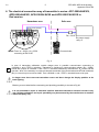


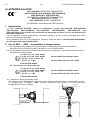
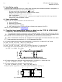
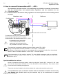


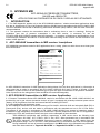

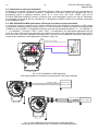
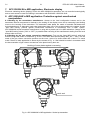


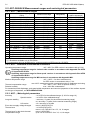
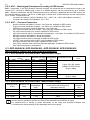


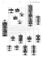
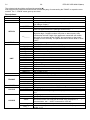

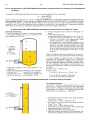


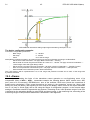
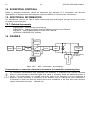
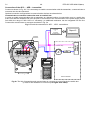
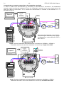
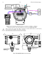
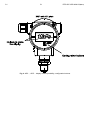


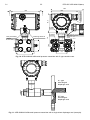
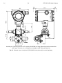
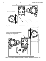

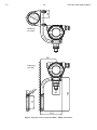
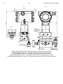
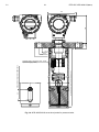
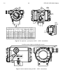
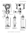

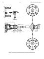
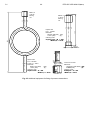


![[17] User`s Manual ver. 2.0.2](http://vs1.manualzilla.com/store/data/005765389_1-e376d351ef2708f30fcfdc5f98b9ba18-150x150.png)