1
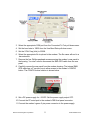
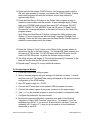
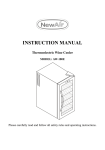
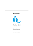
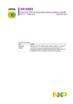
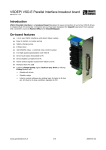
Technical Brief
AN136 Rev C24
2320 Cousteau Court
1-760-444-5995
[email protected] | www.raveon.com
Uploading Software to the RV-M7 Flash
By Adam Hickerson
Raveon Technologies Corp
Overview
This Technical Brief describes how to upload firmware into the RV-M7 transceiver.
The RV-M7 series transceivers utilize a Phillips ARM-based Microprocessor with
internal FLASH memory.
All RV-M7-GX series transceiver use an LPC2136 processor, which has 256kB of
flash memory.
Phillips Semiconductor provides a utility to upload firmware into the microprocessor.
Their program is called “LPC2000 Flash Utility” This utility may be used in the field to
upload new firmware into the RV-M7 series transceivers.
Procedure
1.0
Uploading Firmware
1. Extract the .zip files if the firmware update was supplied in .zip format.
2. Open the Philips Flash Utility Installation.exe file inside the LPC21xx folder. The
version must be V2.2.3 or higher. Walk through the installation steps to install
the Philips Flash Utility program. The Utility program should open when the
installation is complete. The Utility program window is shown below.
Raveon Technologies Corporation
1
www.raveon.com
3. Select the appropriate COM port from the Connected To Port pull-down menu.
4. Set the baud rate to 19200 from the Use Baud Rate pull-down menu.
5. Set the XTAL Freq (kHz) to 20000.
6. Select the appropriate file to upload to the modem. The file name will end in a
.hex extension.
7. Remove the four Phillips panhead screws securing the modem’s rear panel to
the housing. You don’t need to disconnect the SMA GPS cable from the rear
panel.
8. Carefully remove the rear panel from the modem housing. The internal SMA
GPS cable has a 2” service loop to allow access to the modem’s CONFIG
button. The CONFIG button location is shown below.
9. Set a DC power supply for +12VDC. Set the power supply output OFF.
10. Connect the PC serial port to the modem’s DB9 front panel connector.
11. Connect the modem’s green 2-pin power connector to the power supply.
Raveon Technologies Corporation
2
www.raveon.com
12. Press and hold the modem CONFIG button. Set the power supply output to
ON, wait approximately 2 seconds, and release the CONFIG button. If these
steps were performed correctly the modem’s current draw should be
approximately 30mA.
13. Press the Read Device ID button on the Philips Utility program window to
establish communication with the modem. A reset message saying “Please
reset your LPC2000 board now and then press OK!” will appear. DO NOT
RESET POWER TO THE MODEM. Press the OK button. A “Read Part ID
Successfully” message will appear in the lower left corner of the Flash Utility
program window.
Note: When the Read Device ID button is pressed the Utility program may
display a “Cannot communicate with test board!” message. Disregard this
message. Press the OK button and press the Read Device ID button again to
establish communications with the modem.
14. Press the “Upload to Flash” button on the Philips Utility program window to
upload the .hex file to the flash memory. For standard M7 radio modems, the
file name is 2F700xxx.hex. For M7-GX radios with the GPS option, the file
name is 2F700-GXxxx.hex. xx will be the firmware version number.
15. The Utility program will display a “File Upload Successfully Completed” in the
lower left corner when the file upload is completed.
16. Repeat steps 7 through 14 for any additional modems.
2.0 Configuring the Modem
1. Close the Philips Flash Utility program.
2. Open a terminal program with port settings of 8 data bits, no parity, 1 stop bit,
and flow control off. The Baud Rate setting will depend on the previous modem
configuration of the ATBD setting.
3. Set a DC power supply for +12VDC.
4. Connect the PC serial port to the modem’s DB9 front panel connector.
5. Connect the modem’s green 2-pin power connector to the power supply.
6. Type “+++” on the terminal program to enter the modem’s configuration mode.
7. Configure the product per the user manual.
8. Execute the required initialization commands from each of the following
“Upgrade to Version XXX Firmware” steps below. For example, if you are
upgrading from B9 to C1, you must do all procedures in all steps. If you are
upgrading a B11 radio to C1, then you do not need to do the initialization
commands in step B10.
Raveon Technologies Corporation
3
www.raveon.com
Upgrading to Version B10 Firmware
Version B10 introduced a number of new features and parameters in the M7 radio.
Because these new features have parameters stored in EEPROM, the new features
must be manually initialized on radios that have a previous version of the firmware.
Any radio with a current firmware version less than B10, must have the following
commands executed. If the firmware in the radio is already B10 or higher, you will not
need to do the following commands.
Once the version B10 (or higher) firmware has been loaded into the radio, execute the
following commands:
Set the radio back to factory defaults
AT&F <enter>
Set the group code to 0
ATGP 0 <enter>
Set the charge pump current
CPUMP 13 <enter>
The charge-pump setting. This will vary depending upon the radio model, so consult
the factory for the correct setting, or compare it to a radio with B10 or higher firmware
of the same model that is being upgraded.
Set the channel frequency
ATFX xxx.xxxx<enter> All previously stored frequencies were probably erased with B10
Recalibrate RSSI
AT$A 340<enter> The A/D reading at -100dBm
AT$B 530<enter> The A/D reading at -70dBm
If the radio is a –GX version (GPS )
GPS&F<enter>
GPS X <enter> where X is the desired GPS mode of operation
SLOTQTY 1<enter> Set the number of tdma slots to 1 .
Re-calibrate RF power output calibration
AT$P xx <enter> adjust XX value so that the RF power output is correct. Use a wattmeter
connected to the M7 to read the power. Monitor the current craw, and ensure it does not
exceed 2.8A.
AT$R -10 PA temperature compensation.
Upgrading from B10 or higher to Version B24
Since B10, a number of new features and parameters in the M7 radio. Because these
new features have parameters stored in EEPROM, the new features need to be
Raveon Technologies Corporation
4
www.raveon.com
initialized before the radio will work. Normally, this is done at the factory, but it you are
upgrading the firmware in the field, you should execute the following commands after
you have uploaded B24 into your radio.
Your MUST execute the following commands, based upon the firmware version you
were upgrading from.
Upgrading from Version B13 or lower
FREEWHEEL 120
TDMADATA 0
SLOTNUM -1
(Only if your radio has a GPS and is a –GX version)
(Only if your radio has a GPS and is a –GX version)
(Only if your radio has a GPS and is a –GX version)
ATJF 3000
Upgrading from B24 or higher to Version C1
Since the release of B24, a number of new features and parameters in the M7 radio.
Because these new features have parameters stored in EEPROM, the new features
must be initialized before the radio will work properly. Normally, this is done at the
factory, but it you are upgrading the firmware in the field, you should execute the
following commands after you have uploaded C1 into your radio.
Your MUST execute the following commands, based upon the firmware version you
were upgrading from. Update the firmware to C1 first by loading it into the modem
using the Philips Flash utility. Then, after C1 is loaded, execute these 5 commands to
initialize their parameters.
BANDL xxx Set the lower end of the band, in MHz. For example if your radio
is a 450-470Mhz radio, the BANDL must be BANDL 450.
BANDH xxx
Set the upper end of the radio band, in MHz.
PASSWORD 0
of the firmware.
Disables the user password feature introduced in version C
CPUMPL 0 Charge pump compensation at low end of the band.
CPUMPH 0 Charge pump compensation at the high end of the band.
ATLT 0 Default lock time.
Once these five commands have been executed, the radio will be ready to be put into
service.
Upgrading from C1 or higher to Version C7
Since the release of C1, a number of new features and parameters in the M7 radio.
Because these new features have parameters stored in EEPROM, the new features
must be initialized before the radio will work properly. Normally, this is done at the
factory, but it you are upgrading the firmware in the field, you should execute the
following commands after you have uploaded C1 into your radio.
ATCD -113 Set the carrier detect threshold in dBm.
Raveon Technologies Corporation
5
www.raveon.com
Upgrading from C5/C7 or higher to Version C23
Since the release of C7, a number of new features and parameters in the M7 radio.
Because these new features have parameters stored in EEPROM, the new features
must be initialized before the radio will work properly. Normally, this is done at the
factory, but it you are upgrading the firmware in the field, you should execute the
following commands after you have uploaded C1 into your radio.
ATCD -113 Set the carrier detect threshold in dBm.
ATLA FFFF Disable the default “Listen Address”
AT$H 0 Set the command-timeout default to “On Line”. 0=Online, 1=Offline.
Raveon Technologies Corporation
www.raveon.com
[email protected]
Ph +1-760-457-1620
Raveon Technologies Corporation
6
www.raveon.com