1
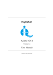
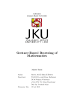
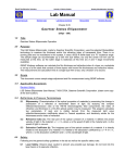
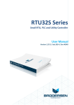
Technical Brief
AN122
Raveon Technologies Corp
Technical Brief
AN122 Rev C1
M7 Series Modems for SCADA Applications
By John Sonnenberg
Raveon Technologies Corp
Summary
The M7™ series of data radios from Raveon Technologies make ideal wireless
modems for SCADA and telemetry systems. This Application Brief describes the
general requirements for a wireless SCADA modem and then provides the information
needed to configure an M5 or M7 series modem to work in common SCADA
applications.
Wireless SCADA
In a traditional wired SCADA system, a device is monitored by some type of computer
or other human-to-machine interface. The user may have something as simple as an
LED indicator, or as complex as a computer server for the operator. The human
interface communicates to another electronic device that is remotely located at the
monitored location. Often this remote device is a Remote Terminal Unit (RTU) or
Programmable Logic Controller (PLC).
Copyright 2006
Last updated: January 2013
1
Raveon Technologies Corp.
Typical SCADA System
When the distance between the monitoring station and the device being monitored (the
water tank above) is not trivial, than a wireless link between the two sites becomes a
logical means of connecting them.
Raveon’s Features for SCADA Applications
High-speed over the air data rates. 19200bps in 25kHz channel, 9600bps in 12.5kHz.
Remote status monitoring including DC voltage, packet error statistics, modem “up
time”, and receiver signal strength.
Easy to use. Plug-in, Turn-on, and GO. Transmit data in = Receive data out.
Lowest current draw in industry. The M7 wireless modems draw less than 90mA in
the receive mode.
Wide input voltage with high-efficiency switching voltage regulator.
Technical Brief
AN122
Raveon Technologies Corp
Packetized AND Streaming Data. Integrated Packetized data protocol with error
correction and built-in Streaming Real-Time operation. User selectable.
ARQ error correction and retransmission capability. Totally transparent to the
application.
Capable of store-and-forward repeating operation.
Small size. Extruded aluminum enclosure is small, and very rugged.
16 bit addressing for up to 65,525 different unique device addresses per channel.
Radio channels may be shared with no interference between users.
Supports group and broadcast transmissions. Network mask allows groups of any
size.
Easily to configure. Raveon modems are configured using “AT” commands through
the modem’s serial port. Raveon also provides free of charge, Radio Manager, a easyto-use PC program with a graphical user interface to configure and program all Raveon
Radios.
RS-232, RS-422, or RS-485 serial port. Programmable serial baud rates up to 115200
make the M7 radio modem compatible with most every PLC, PC, and HMI device made.
Programmable over-the-air data rates. With the M7 radio modem, you can choose
how your system will work. Set the OTA data slower for extended communication
range, or set it fast for lowest latency. Your choice.
SkyLine compatibility mode for use in older Sonik radio systems.
Going Wireless
Wired Connection
The telemetry industry has standardized on a number of different protocols to use in
these types of applications. Most protocols were based upon the assumption that the
cabling between the monitoring station and the RTU/PLC is an RS-232 or RS-422 serial
link. The protocols commonly used on these serial links are MODBUS-RTU, MODBUSASCII, DF1, DNP-3, and IEC870. All of these protocols can operate using hard-wired
connections. Because the Raveon Radios mimic a hard-wire (data-in equals data-out),
in most cases, the protocols will also work using a wireless modem.
M7 Modems with Modbus
Raveon radio modems support Modbus-ASCII networks with no special configuration.
Modbus-ASCII was designed specifically to work well over wired and wireless modems,
and uses 7-bit data. All Raveon modems support 7-bit data.
Modbus-RTU uses 8-bit data. Some modems and older systems do not work with 8-bit
data, but Raveon’s wireless modems support both 7 bit and 8 bit data. There are some
considerations when using radio modems with Modbus-RTU:
Latency The difference between M5 and M7 series wireless modems and a multi-drop wired network is
that the wireless modems introduce some additional latency (delay) into the system. Most Modbus-RTU
applications can tolerate this latency, but some cannot. If your Modbus application does not tolerate
Copyright 2006
Last updated: January 2013
3
Raveon Technologies Corp.
latency, then use Modbus –ASCII. Modbus-ASCII is compatible with Raveon radio modems. The
following table shows Latency vs. Over-the-air bit rate for Raveon narrow band radio modems in the
packetized mode.
Bit Rate
ATR2 Setting
Latency (Seconds)
800 (2L)
1200 (2L)
2400 (2L)
4800 (2L)
5142 (2L)
8000 (4L)
0
1
2
3
7
4
0.8-0.9
0.5-0.6
0.3-0.4
0.2-0.3
0.2-0.3
0.2-0.3
Time-Outs Some versions of the Modbus protocol have short response timeout requirements that may
not be compatible with radio modem latencies. Modbus-RTU is compatible with the normal FireLine
latencies but does have inter-character delay requirements that must be met. Raveon modems have
programmable time-outs to facilitate the control of latency.
Modem IDs
The M5 and M7 series modems have 16 bit IDs. Most SCADA systems work in a
broadcast configuration, where all modems hear all other modems. To do this, set the net mask to all
zeors (ATMK 0000). Be sure to set each unit ID in each modem to a unique ID number, so that the
duplicate packet filtering works properly. All Raveon modems filter out duplicate packets, so that
operation with repeaters does not cause duplicate packets being received.
For lowest latency, Raveon’s unique “Streaming” mode of operation provides data
transfer with latency only slightly higher than wired configurations. No other radio
modem on the market offers both error-free packetized operation AND Streaming data
operation.
M7 Modems with DF1
The DF1 protocol works well with the Raveon radio modems as long as the over-the-air
data rate is set to 4800 bps or higher. The stock-configuration of the radio modem
works with the Rockwell “DF1 Polling Driver”.
To reduce latency in the polling, it is suggested that certain stock-parameters in the
FireLine be a adjusted to values more optimized for use in a polled environment. The
following is a list of parameters in the radio that may be adjusted to reduce latency
when using the DF1 protocol.
1) Reduce the serial-port time-out value down to 2mS (ATR3 2)
2) Set the serial port to 19200bps (ATBD 4)
3) Configure the Over the air data rate to 8000bps (ATR2 4) This will reduce the
communication range, so only do this if the link-margin on the system is
adequate.
4) Use the “Streaming Mode” of communications.
(ATMT 2) The factory default is
the “Packet Mode”, where all data is error checked and sent in packets. The
Streaming mode initiates transmissions faster, and sends characters over-the-air
as they stream in, but does not check for errors. DF1 is tolerant of noise and
over-the-air bit errors, and in most cases works well in streaming mode. In
Technical Brief
AN122
Raveon Technologies Corp
mission-critical or safety situations, packet mode would be more appropriate as
it’s data transmission is more deterministic.
Configuring the M5 or M7 Radio
For SCADA applications, configure the radio as per the user manual. In most cases,
the factory defaults are the best place to start. Set the frequency using the ATFX
xxx.xxxx command. Then, based upon your system, configure the following
parameters:
“AT”
command
Function
ATBD
Set the baud rate of the FireLine’s serial port. Typically set the serial-port
rate to 2400 or 9600bps, whichever matches your hardware’s setting. Given
a choice, Raveon suggests you set it at a high rate to reduce latency. 9600
is set with the ATBD 3 command. 19200 is set with the ATBD 4 command.
Enable/disable Busy Channel Lockout. Normally, the radio modem does not
check for a busy channel. If you are running a large system, with
asynchronous data on the radio channel, you should enable BCL so the
modem does not transmit while another device is on the air. For polled
telemetry systems, do not enable this feature.
Enable/Disable hardware flow control. By default this is off and will work fine
in most applications. Enabling hardware flow control will ensure that the
modem buffers data and only outputs it to the user’s device or RTU when the
device is ready to receive it.
Used to set the radio frequency of the modem.
Set the parity bit method of the serial port. Odd, even, none, mark or space.
You must configure this to match the device the FireLine is communicating
with. Note: Parity, baud Rate, and stop bits may be configured differently on
different ends of the radio link.
The over-the-air data rate. For long-range, set it at 4800bps. For lowest
latency, set it at 8000bps or 9600bps. ATR2 3 for 4800baud. ATR2 4 for
8000 baud.
Serial port time out. This is the amount of idle-time (in mS) before the
FireLine will begin to transmit a packet of data. When no data comes into the
modem for this amount of time, the FireLine will transmit the contents of its
data buffer over the air. The factory default setting is 20mS. For SCADA
systems using MODBU, 2mS is suggested (ATR3 5).
The M5 and M7 series modems have 16 bit IDs. Most SCADA systems work
in a broadcast configuration, where all modems hear all other modems. Be
sure to set the unit ID in each modem to a unique ID number, so that the
duplicate packet filtering works properly.
To turn off address filtering, and allow all units to receive data from all other
units, set the net mask to all zeros (ATMK 0000).
ATBC
ATCH
ATFX
ATNB
ATR2
ATR3
ATMY
ATMK
For example, with a modem configured for 8000 baud over the air, 9600baud serial
ports, 2mS time-out, the total time for a MODBUS “Read Module Name” command
($01M) command to receive the response back is 150mS in Packet Mode.
Copyright 2006
Last updated: January 2013
5
Raveon Technologies Corp.
A DF1 polling system with M5 Fireline or M7 modems configured for 8000 baud over the
air, 9600baud serial ports, 2mS time-out, and Streaming Mode will allow RTU’s to be
polled and responses returned in about 80mS round-trip.
Repeating For Extended Range
For longer communication ranges, high RF noise environments or obstructed line of
sight applications it may be necessary to use a repeater to establish a reliable
communications link.
Incorporated in the radio is a built in store-and-forward repeater function. The repeater
function works only in the Packet Mode, and will not repeat streaming messages. A
repeater can extend the range of a system by 2-20X, depending upon how high-up
above the average terrain the repeater is mounted.
The following table shows a typical repeater system configuration in packetized mode.
AT
Comman
d
Monitorin
g
Modem
Repeater
Modem
Remote
Modem
Notes
ATMY
1000
2000
00010999
ATDT
0001
N/A
1000
ATMK
F000
0000
F000
ATXR
0
1
0
ATX1
N/A
1000 0000
1000 0000
N/A
Individual unit address for this
particular modem. Each
remote modem should get a
unique ID.
Destination address to send
data to.
Address mask. F000 means
that to receive, the first digit of
the MYID must match the first
digit of the TOID.
Enable/Disable repeater
function. Only enable it on the
particular radio that will be the
repeater.
In the repeater, set the
addresses this unit will storeand-repeat to/from. By setting
the repeater address mask to
Technical Brief
AN122
Raveon Technologies Corp
0000, this repeater will repeat
any and all data packets .
Serial Port
RS232 or RS485
Raveon’s M5 and M7 radio modems come standard with RS-232 serial ports. They
may be ordered with an RS-422 and RS-485 options.
For SCADA systems, a typical configuration is to have the radio modem connected to
the HID/computer to have an RS-232 serial port. The RTUs in the field usually use RS485, so the radio modems connected to the RTUs should have the RS-485 option
installed. A system may mix RS232 and RS485 modems with no adverse
consequences.
Buffer Status
On the M7 series of radios, there is a command ATJF that will allow the user to set the
CTS threshold. By default, this is set to 80% of the buffer’s size. When the internal data
buffer of the M7 reaches this threshold, the CTS hardware handshake line is negated.
The user may change this threshold. If you want the M7 CTS line to indicate when
there buffer is empty (all data has been transmitted), then set the ATJF parameter to 1
(ATJF 1). This will have the effect of negating CTS whenever there is any data in the
M7’s data buffer. When all data has been transmitted over-the-air, the CTS line will be
asserted again. It is a handy way to receive a hardware indication that a transmission
has gone out, and the radio is ready for more data.
But remember, regardless of the ATJF setting, the M7’s data buffer can hold thousands
of bytes of data, queuing them up to be sent over the air. The ATJF command only
affects the threshold where CTS is asserted, not the size of the internal data buffer in
the 7.
For additional information, contact:
Raveon Technologies Corporation
2461 Impala Drive
Carlsbad, CA 92010 - USA
Phone: 1-760-444-5995
Fax: 1-760-444-5997
Email: [email protected]
Copyright 2006
Last updated: January 2013
7
Raveon Technologies Corp.