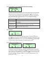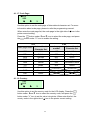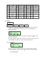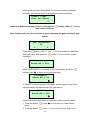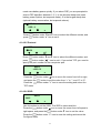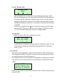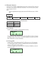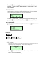
1
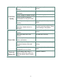
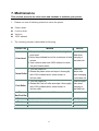
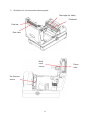
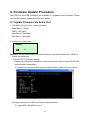
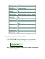
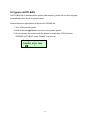
M23 Direct Thermal Portable Printer USER’S MANUAL Contents Copyright Declaration ...................................................................................1 Compliances ..................................................................................................1 1. INTRODUCTION .........................................................................................2 1.1 Documentation.........................................................................................2 1.2 Unpacking and Inspection ......................................................................2 1.3 Equipment Checklist ...............................................................................2 1.4 Front View.................................................................................................3 1.5 Rear View..................................................................................................5 2. GETTING STARTED ...................................................................................6 2.1 Install the Battery.....................................................................................6 2.2 Using the Strap ........................................................................................7 2.2.1 Hand Strap......................................................................................7 2.2.2 Shoulder Strap ( Option ) ..............................................................8 2.3 Loading Media..........................................................................................9 2.3.1 Loading Continuous Labels for Receipt Paper ...........................9 2.3.2 Loading Die-cut Labels ...............................................................10 2.3.3 Loading Fan-fold Labels .............................................................12 2.4 Connecting the Communication Cable ................................................14 2.5 Using the Bluetooth Wireless (Optional) .............................................15 2.6 Charging the Battery .............................................................................16 3. USING THE DISPLAY AND BUTTONS ....................................................18 3.1 LCD Display and Buttons......................................................................18 3.2 LCD Display Icon Description...............................................................19 3.3 LCD/Keyboard Operation ......................................................................20 3.3.1 Turn on/off the Printer .................................................................20 3.3.2 Arrow Keys ...................................................................................20 3.3.3 Exit From a Menu .........................................................................20 3.3.4 Cancel the Error Status ...............................................................20 4. LCD MENU OVERVIEW............................................................................21 4.1 Setup.......................................................................................................23 4.1.1 Printer Setup ................................................................................23 4.1.2 Sensor...........................................................................................27 4.1.3 Serial Comm.................................................................................33 i 4.1.4 RF Network ( Optional ) ...............................................................35 4.1.5 Bluetooth ( Optional ) ..................................................................39 4.1.6 Display ..........................................................................................40 4.1.7 Power Manager (Low Power, Shut Down)..................................41 4.2 File Manager ...........................................................................................42 4.2.1 File List .........................................................................................42 4.2.2 Avail. Memory...............................................................................43 4.2.3 Del. All Files..................................................................................43 4.3 Diagnostics ............................................................................................44 4.3.1 Print Config. .................................................................................44 4.3.2 Dump Mode ..................................................................................45 4.3.3 Battery ..........................................................................................45 4.3.4 Print Head.....................................................................................45 4.3.5 Display ..........................................................................................46 4.3.6 Buttons .........................................................................................46 4.4 Language................................................................................................48 4.5 Service ....................................................................................................49 4.5.1 Initialization ..................................................................................49 4.5.2 Mileage Info. .................................................................................50 5. PRINTING LABELS ..................................................................................51 5.1 Connect with a Cable to Print ...............................................................51 5.2 Connect by Radio (Optional) ................................................................51 5.3 Stand-along Printing..............................................................................52 6. TROUBLESHOOTING ..............................................................................53 7. MAINTENANCE ........................................................................................55 8. FIRMWARE UPDATE PROCEDURE ........................................................58 8.1 Update Firmware Via Serial Port...........................................................58 8.2 Update Firmware Via USB Port .............................................................61 9. POWER ON UTILITIES .............................................................................62 9.1 Printer initialization................................................................................62 9.2 Ignore AUTO.BAS ..................................................................................64 ii Copyright Declaration Information in this manual is subject to change without notice and does not represent a commitment on the part of TSC Auto ID Technology Co., Ltd.. No part of this manual may be reproduced or transmitted in any form by any means, for any purpose other than the purchaser’s personal use, without the expressed written permission of TSC Auto ID Technology Co., Ltd.. The TrueType font engine is developed from the “FreeType Project" by David Turner, Robert Wilhelm, and Werner Lemberg. All other products referred on this document are the trademark or the registered trademark of each belonged companies. Compliances CE Class B: EN55022:1998+A1:2000+A2:2003: EN55024:1998+A1:2001+A2:2003: EN 61000-4 SERIES REQULATIONS ETSI EN 301 489-17:V1.2.1(2002-08) FCC: CFR 47, Part 15/CISPR 22 3RD EDITION:1997, Class B ANSI C63.4:2003 CANADIAN ICES-003 C-Tick: AS/NZS CISPR22 (Class B) UL, CUL UL 60950 3rd TÜV-GS: EN60950: 2000 Wichtige Sicherheits-Hinweise 1. Bitte lesen Sie Diese Hinweis sorgfältig durch 2. Heben Sie diese Anleitung fűr den späteren Gebrauch auf. 3. Vor jedem Reinigen ist das Gerät vom Stromentz zu trennen. Verwenden Sie Keine Flűssig-oder Aerosolreiniger. Am besten eignet sich ein angefeuchtetes Tuch zur Reinigung. 4. Die Netzanschlußsteckdose soll nahe dem Gerät angebraucht und leicht zugänglich sein. 5. Das Gerät ist vor Feuchtigkeit zu schűtzen. 6. Bei der Aufstellung des Gerätes ist auf sicheren Stand zu achten. Ein Kippen oder Fallen könnte Beschädigungen hervorrufen. 7. Beáchten Sie beim Anschluß an das stromnetz die Anschlußwerte. 8. Dieses das Gerät kann bis zu einer Außentemperatur von maximal 40℃ betieben werden. 1 1. Introduction Thank you for purchasing TSC M23 direct thermal printer. M23 is a portable printer, which can accept varieties of media, such as labels, receipt, tag, and fan-fold paper. With LCD display, it is more user friendly for operation and more easily for understanding printer status. With 802.11b WiFi and Bluetooth connectivity, M23 extends the mobile printing technology needs. 1.1 Documentation This document provides an easy reference for operating the TSC M23 Printer. The online version of the Programmer's manual, or more information can be downloaded from service and support web site as an Adobe® Acrobat® Reader file. 1.2 Unpacking and Inspection This printer has been specially packaged to withstand damage during shipping. Please carefully inspect the packaging and printer upon receiving the bar code printer. Please retain the packaging materials in case you need to reship the printer. 1.3 Equipment Checklist Unpacking the printer, the following items are included in the carton. One M23 printer One software CD disk One hand strap One Lithium-ion battery One single bay battery charger and power adapter One quick start guide If any parts are missing, please contact the Customer Service Department of your purchased reseller or distributor. 2 1.4 Front View Context-sensitive keys Supply door release button Paper exit chute Caution: Hazardous parts. Keep fingers and other body parts away. Tear plate (for label) Peel roller Tear bar (for liner) 3 Platen Gap/black mark sensor Supply holder Peel-off enabler Li-ion battery Strap button Graphic LCD with back lit display 4 1.5 Rear View Hinged cable door Fan-fold paper entrance chute Power jack chute RS-232 interface 5V/DTR switch USB interface 5 2. Getting Started 2.1 Install the Battery 1. Open the supply door by pulling outward on the release buttons located on either side of the printer.The supply door should swing open. Supply door Release button 2. Insert the connector end of the battery into the printer. Li-ion battery Release button 3. After loading media, close the supply door until the release buttons click into place. 6 2.2 Using the Strap 2.2.1 Hand Strap 1. Clip both rings of the hand strap onto the strap buttons by placing each O-ring over the strap button and gently pulling up on the strap until the strap until the strap locks into place. Hand strap Strap button O -rings 7 2.2.2 Shoulder Strap ( Option ) Shoulder strap 8 2.3 Loading Media 2.3.1 Loading Continuous Labels for Receipt Paper 1. Open the supply door by pulling outward on the release buttons on both sides of the printer. 2. Pull supply holder tabs apart and insert a new roll of media. Make sure the media is positioned so it unwinds from the top as shown. A roll of supplies Release button Supply holder tabs 3. Pull out enough supply to lie across the exit chute. Label Supply door 9 4. Close the supply door until the release buttons click into place. Paper exit chute Note: Please set the sensor type as Continuous. 2.3.2 Loading Die-cut Labels 1. Open the supply door by pulling outward on the release buttons on both sides of the printer. Peel bar Supply holder Peel roller Peel off enablers 10 2. Lift up the peel off enablers on both sides. Push down the peel off enablers Lift up the peel off enablers 3. Pull supply holder tabs apart, and insert a roll of labels. Make sure the supply unwinds from the top as shown. Note: Calibrate the gap/black mark sensor when changing media. A roll of label. Release button Supply holder tabs 4. Remove a couple of labels from the liner. Insert the liner through the gap between peeler bar and peel-off roller. Peel roller Peeler bar Tear edge ( for liner) Liner 11 5. Close the supply door. 6. Press the button once or twice to advance the labels until the liner is separates from the label. Label Liner 2.3.3 Loading Fan-fold Labels 1. Open the supply door by pulling outward on the release buttons on both sides of the printer. 2. Pull supply holder tabs apart to insert a 3” paper core to keep supply holder wide open. 3” Paper core 3. Insert the fan-fold paper through the fan-fold paper entrance chute and pass over the paper exit chute. 12 Fan-fold paper entrance chute Fan-fold media 4. Adjust the paper guides by sliding to fit the paper width. Paper guides 5. Close the supply door. 6. Calibrate the media if necessary. Note: Please calibrate the gap/black mark sensor when changing media. 13 2.4 Connecting the Communication Cable 1. Open the hinged cable door by loosening the two screws. Lift up on the door. Hinged cable door Screws 2. Plug the null modem cable into the RS232 port. (Or plug the USB cable into the USB port.) RS232 port USB port 5V/DTR Switch 3. Place the cable in the cable cavity. RS232 port Cable cavity Null modem cable 4. Close the hinged cable door and tighten the screws. 14 2.5 Using the Bluetooth Wireless (Optional) 1. Open the hinged cable door by loosening the two screws and lifting up on the door. 2. Set the +5V / DTR switch to the +5V position. 5V/DTR switch 3. Plug in the Bluetooth dongle into the RS-232 port. Hinged cable door Bluetooth 4. Close the hinged cable door and tighten the screws. 5. Then, please to refer the section 4.1 to calibrate the bluetooth. 15 2.6 Charging the Battery 1. Open the printer supply door and remove the battery. 2. Insert the battery into the charger station. Battery Power LED Status LED Power LED Description Red Power is on Off Power is off Status LED Description Red Charging battery Amber Battery is 70% charged Green (Solid) Battery is completely charged Green (Blinking) Charger error Off No battery Note: 1. If Power LED is solid red and Status LED is green blinking, please remove the battery and check if the terminals inside the charger are shorted by foreign object. Unplug the charger power adapter from the outlet and remove the object between “+” and “-“ terminals. Install the battery to the charger for charging again. If problem still exists, please contact your purchased reseller for service. 2. It takes 2 to 3 hours to fully charge the battery before the first time usage. The 16 lifetime of the battery is 300 times for charge/discharge cycles. 17 3. Using the Display and Buttons 3.1 LCD Display and Buttons Navigation buttons LCD display Feed/Ready button On/Off button Icon Description Turns the printer on and off. Advances label or returns the display to the previous menu. Three buttons that selecting options on the display. 18 3.2 LCD Display Icon Description Icon Description Enter the menu ] Enter cursor located option © Scroll up ª Scroll down ¨ Cursor location + Increase the setting value - Decrease the setting value × Cancel OK/select 3 Return the display to the next higher menu. ll Pause and display the battery voltage 19 3.3 LCD/Keyboard Operation ¨Option ª © ] 3.3.1 Turn on/off the Printer Hold the button to turns on/off printer. 3.3.2 Arrow Keys Press the Press the Press the button under the ª LCD icon to scroll down the menu list button under the © LCD icon to scroll up the menu list. button under the ] LCD icon to enter cursor located option 3.3.3 Exit From a Menu 1. Press the button to exit from a menu or cancel a setting and return to the next higher menu. 2. When the cursor ¨ icon is pointed to the “Exit”, press the under the ] LCD icon on the display, to exit from an option. button, which is 3.3.4 Cancel the Error Status Press the button to cancel the error status to resume printer back to normal. 20 4. LCD Menu Overview Ready Setup Printer Setup Speed USA 001 (default) 1 BRI 002 1.5 ips 2 GER 003 2.0 ips (default) 3 GER 031 2.5 ips 4 DAN 032 3.0 ips 5 ITA 033 3.5 ips 6 SPA 034 7 (default) SW E 036 0 (default) 8 SW I 038 Density Direction 0 1 9 437 039 Tear Off Mode 10 850 (default) 041 Batch Mode (default) 11 852 042 Peeler Mode 12 860 044 Exit 13 863 045 +000 (default) 14 865 046 Reference X 000 (default) 15 Reference Y 000 (default) Print Mode Offset 857 047 Exit 048 Code Page 049 Country 055 Exit Sensor 061 Gap Sensor Auto Gap 351 Manual Gap Serial Com m . 358 Exit 1200 bps Bline Sensor Auto Bline 2400 bps Continuous Manual Bline 4800 bps Exit Exit 9600 bps (default) Exit 19200 bps Baud Rate Parity Data Bits None (default) 38400 bps Odd 57600 bps Even 115200 bps Exit Exit 7 Data Bits 8 Data Bits (default) Exit Stop Bits One Stop Bit Exit Two Stop Bits (default) Exit RF Network Bluetooth Display File Manager Diagnostics Status IP Address Security Enable Configure Subnet Mask CAM Change PIN Disable Reset Gateway PSP Local Nam e Exit Exit Power Mode Exit Inform ation Protocol TCP Exit SSID LPD Exit Contrast 50 (default) Escape Backlight Disable (default) Exit Exit Enable Power Manager Low Power 5 Seconds Exit Shut Down 10 Seconds Exit 30 Seconds File List Filenam e 1 Minute Avail. Mem ory DRAM: xxx KB Free 5 Minutes Del. All Files FLASH:xxx KB Free 10 Minutes Exit 30 Minutes Printer Config. 1 hour Dum p Mode 5 hours Battery Exit Print Head Display Buttons Exit Language English Service Initialization Exit Mileage Info. Exit Exit 21 Main Menu Setup - File Manager - Diagnostics - Language - Service - Exit 1. Turn on the printer by pressing and holding the button until the display turns on. The display flashes printer version information, battery voltage gauge, and then you see: State Ready Menu icon Pause icon ll Note: At ready states press ll icon can check battery voltage gauge. (Press the same button to go back to Ready states.) Pause E 2. Press the F button under the icon to enter the Main menu. ¨Setup File Manager ª ] 22 4.1 Setup Setup Printer Setup - File Manager - Diagnostics - Language - - Sensor - Service - Exit Serial RF Power - Bluetooth - Display Comm. Network Manager Exit 4.1.1 Printer Setup Printer setup Speed - Density - Direction - Print Reference Reference Code - Offset - Country - Exit Mode X Y Page 4.1.1.1 Speed: + Speed 2.0 ips - v Use this option to setup print speed. The available print speed is between 1.5~3.5 ips and increament/decreament is 0.5 ips. The default print speed is 2.0 ips ( 50mm/sec). button under “+” icon to raise the print speed, and “–” icon to lower Press it, and “V” icon to set it into printer. Note: 1. Media width, label printing content, density setting and battery voltage will affect printing speed. Printer will adjust the printing speed automatically to optimize printing quality. 2. In peel off mode, the printing speed will be set to 1.5 ips automatically. 23 4.1.1.2 Density: + Density 7 - v Use this option to setup printing darkness. The available setting is from 0 to 15, and the step is 1. Printer default density is 7.You may need to adjust your density based on selected media. Press button under “+” / “-” icons to increase/decrease the printing darkness. Press button under “V” icon to enable the setting. Note: Density setting will affect printing speed. Printer will adjust the printing speed automatically to optimize the printing quality. 4.1.1.3 Direction: Direction 0 + v The direction setting value is either 1 or 0. Use this option to setup the printout direction. Printer default printout direction is DIRECTION 0. button under “+” icon to set the direction as 1, and “–” icon to set it Press as 0, and “V” icon to enable the setting. The following 2 figures are the printouts of DIRECTION 0 and 1 for your reference. DIRECTION 0 DIRECTION 1 24 4.1.1.4 Print Mode: (Tear Off Mode/Batch Mode/Peeler Mode) ¨Batch Mode Peeler Mode ª © V This option is used to set the print mode. Printer default setting is Batch Mode. When enter this list, the print mode in the right side of ¨ icon is the printer button under ª and © icon to select the different button under “V” icon to enable the setting. current setting. Press print mode, and press Printer Mode Description Tear Off Mode: Next label leading edge is aligned to the print head burn line location. Batch Mode: Once image is printed completely, label gap/black mark will be fed to the tear plate location for tear away. Peeler Mode: Enable the label peel off mode. 4.1.1.5 Offset: Offset +000 ¨ ª V This option is used to fine tune media stop location. Press the button under ¨ icon to move the cursor from left digit to right digit, and press the button to set the value from “+” to “-” or “0” to “9”. Press the button under “V” icon to set the value into printer. The default value is +000. 4.1.1.6 Reference X & Reference Y: Reference Y 000 Reference X 000 ¨ ª ¨ V ª V This option is used to set the origin of printer coordinate system horizontally button under ¨ icon to move the cursor from left and vertically. Press the digit to right digit, and press the button under ª icon to set the value from “0” to “9”. Press the button under “V” to set the value into printer. The default value is 000. 25 4.1.1.7 Code Page: ¨850 852 ª © V Use this option to set the code page of international character set. For more information about code page, please to refer the programming manual. When enter the code page list, the code page in the right side of ¨ icon is the printer current setting. Press the button under ª and © icon to select the code page, and press the button under “V” icon to enable the setting. 7-bit 8-bit code page name International Character Set code page number International Character Set USA USA 437 United States BRI British 850 Multilingual GER German 852 Slavic FRE French 860 Portuguese DAN Danish 863 Canadian/French ITA Italian 865 Nordic SPA Spanish SWE Swedish SWI Swiss 4.1.1.8 Country: 001 ¨002 ª © V Use this option to set the country code for the LCD display. Press the button under ª and © icon to select the country code, and press the button under “V” icon to set the value into printer. When enter this list, the country code in the right side of ¨ icon is the printer current setting. 26 Code Country Code Country 001 USA 034 Spanish (Spain) Hungarian 002 Canadian-French 036 003 Spanish (Latin America) 031 Dutch 032 Belgian Code Country Code Country 044 United Kingdom 055 Brazil 045 Danish 061 English (International) Swedish 351 Portuguese 038 Yugoslavian 046 039 Italian 047 Norwegian 358 041 Switzerland 048 033 French (France) 042 Slovak 049 Finnish Polish German 4.1.2 Sensor Sensor Gap Sensor - Bline Sensor - Continuous - Exit This option is used to set the media sensor type and calibrate the selected sensor. We recommend to calibrate the sensor before printing when changing the media. Gap Sensor ¨Bline Sensor ª © ] When you enter this option, the sensor type in the right side of ¨ icon is the printer current setting. Press the press the button under ª icon and © icon to select the sensor type, and under “]” icon to enter sensor detecting mode. 4.1.2.1 Gap Sensor: ¨Auto Gap Manual Gap ª ] Press the button under ª and © icon to select the sensor detecting mode, and press the button under ] icon to detect sensor strength. 4.1.2.2.1 Auto Gap: 27 When enter the [Auto Gap] option, you will see following message. Normally, we use this option to calibrate the sensor sensitivity. Insert liner ... Then hit Enter V Insert liner between the gap sensors, and press the start sensor calibrate. button under “V” icon to Note: Please make sure the only liner is placed between the gap see-though type sensor. GAP Calibrate 50 + V Press the button under “+” and “-“ icon to increase and decrease Stock AD value, and press the under “V” icon to detect sensor sensitivity. Calibrating ... Stock AD = 256 When “SUCCESSFUL” is shown on the LCD display, press the button under “3” to return to the previous page. SUCCESSFUL Stock AD = 50 3 If “FAILED” is shown on the LCD display, please check if only liner is placed between the see through type gap sensor. FAILED Stock AD = 135 3 Please follow the steps below to calibrate sensor sensitivity again. 1. Press the button menu. under “3” icon to return to “Gap Sensor” 2. Press the button under “]” icon to enter “Auto Gap” menu. 28 3. After insert liner between the see through type gap sensor, press the button under “V” icon to continue. 4. Press the button under “+” icon to increase Stock AD value by 50 increment. And press the button under “V” icon to calibrate the sensor sensitivity. GAP Calibrate 185 + V 4.1.2.1.2 Manual Gap: If Auto Gap sensor calibration can not apply to the media, please use Manual Gap function to calibrate sensor manually. This function can be used to fine tune sensor sensitivity. When enter [Manual Gap] option, you will see following message. Gap Sensor Stock AD = 50 Intension = 140 + V Gap Sensor Stock AD = 163 Intension = 140 + V Stock AD on liner Stock AD on paper Press the button under “+” and “-“ to increase and decrease sensor intension, and press the under “V” to set the value to printer. When adjust the sensor sensitivity manually, we can get the different Stock AD on liner and paper in each sensor intension. The difference between these two values must be larger than 50 levels then printer can register label position correctly. 29 4.1.2.2 Black Sensor: ¨Auto Bline Manual Bline ª ] Press the button under ª and © icon to select the sensor calibration under “]” icon to start sensor calibration. mode, and press the 4.1.2.2.1 Auto Bline: When enter the [Auto Bline] option, you will see following message. Normally, we use Auto Bline to calibrate sensor sensitivity. Insert label ... Then hit Enter V Insert label on the black mark sensors, and press the to start sensor calibration. button under “V” icon Bline Calibrate 150 + V Note: DO NOT align black mark to the black mark sensor when calibrate black mark sensor or sensor will be calibrated incorrectly. button under “+” and “-“ icon to increase and decrease Press the Stock AD value, and press the under “V” icon to calibrate sensor. Calibrating ... Stock AD = 256 SUCCESSFUL Stock AD = 150 3 When sensor is calibrated successfully, press the “3” icon to return to the previous page. button under If “FAILED” is shown on the LCD display, please check if only paper 30 (without black mark) is placed on the black mark sensor. FAILED Stock AD = 190 3 If yes, please follow the following steps to calibrate sensor sensitivity agian. 1.Press the button under “3” icon to return to Bline Sensor menu. 2. Press the button under “]” icon to enter “Auto Bline” menu. 3. After insert paper on the black mark sensor, press the button under “V” icon to continue. 4. Press the button under “+” icon to increase Stock AD value by 50. And press the button under “V” icon to calibrate the sensor sensitivity. Bline Calibrate 240 + V 4.1.2.2.2 Manual Bline: If Auto Bline sensor calibration successfully, it’s not necessary to calibrate the sensor manually. This function is used to fine tune sensor sensitivity. When enter the [Manual Bline] option, you will see following message. Gap Sensor Stock AD = 153 Intension = 212 + V Gap Sensor Stock AD = 249 Intension = 212 + V Stock AD on label Stock AD on black Press the button under “+” and “-“ to increase and decrease sensor intension, and press the under “V” to set the value to printer When adjust the sensor sensitivity manually, we can get the different Stock AD on black mark and paper in each sensor intension. And the difference between these two values must be larger than 50 levels then printer can register the label correctly. 4.1.2.3 Continuous: 31 When enter the [Continuous] option, you will see following message. Insert label ... Then hit Enter V Insert media between the gap sensor and press the start sensor calibration button under “V” icon to Calibrate 50 + V Press the button under “+” and “-“ icon to increase and decrease Stock AD value, and press the under “V” icon to detect sensor sensitivity. Calibrating ... Stock AD = 256 SUCCESSFUL Stock AD = 50 3 Press the button under “3” icon to return to the next higher menu. If “FAILED” is shown on the LCD display, please check if the media is placed between the see through type gap sensor. FAILED Stock AD = 50 3 If yes, please follow the following steps to calibrate sensor sensitivity agian. 1. Press the button under “3” icon to return to “Sensor” menu. under “]” icon to enter “Continuous” menu. 2. Press the button 3. After insert label between the see through type gap sensor, press the button under “V” icon to continue. 4. Press the button under “+” icon to increase Stock AD value by 50 levels. Press the button 32 under “V” icon to calibrate the sensor sensitivity. Calibrate 100 + V 4.1.3 Serial Comm. Serial Comm. Baud Rate Options Baud Rate Parity Data Bits Stop Bits - Parity - Data Bite - Stop Bits - Parameters 1200 bps/ 2400 bps/ 4800 bps/ 9600 bps / 19200 bps/ 38400 bps/ 57600 bps/ 115200 bps None/ Odd/ Even 7 Data Bits/ 8 Data Bits 1 Stop Bit/ 2 Stop Bits Exit Default 9600 bps None 8 Data Bits 1 Stop Bit 4.1.3.1 Baud Rate: ¨9600 bps 19200 bps ª © V This option is used to set the RS-232 baud rate, and the default setting is 9600 bps. Press button under ª and © icon to select the different baud rate, and press button under “V” icon to set the value into printer. When you enter this list, the baud rate value in the right side of ¨ icon is current setting in the printer. 4.1.3.2 Parity: None ¨Odd ª © V 33 This option is used to set the RS-232 parity. The default setting is None. Press button under ª and © to select the different parity, and press button under “V” to set the value into printer. When you enter this list, the parity in the right side of ¨ is the printer current setting. 4.1.3.3 Data Bits: ¨8 Data Bits Exit ª © V This option is used to set the RS-232 Data Bits, and the default setting is 8. Press button under ª and © icon to select the different Data Bits, and press button under “V” icon to set the value into printer. When you enter this list, the Data Bits in the right side of ¨ icon is the printer current setting. 4.1.3.4 Stop Bits: One Stop Bit ¨Two Stop Bits ª © V This option is used to set the RS-232 Stop Bits. The default setting is 1. Press button under ª and © icon to select the different Stop Bits, and press button under “V” icon to set the value into printer. When you enter this list, the option in the right side of ¨ icon is the printer current setting. 34 4.1.4 RF Network ( Optional ) Use this menu to configure optional 802.11b WiFi configuration. Checking the printer’s WiFi module status, configure the RF network settings, and reset the WiFi module. Note: Before using WiFi module, please set the RS-232 baud rate to 19200 bps. RF Network Status - Configure - Status ¨Configure ª © Reset - Exit ] Press button under ª and © icon to select the different options, and press button under “]” icon to enter the option. 4.1.4.1 Status: (Checking the Status) 000.000.000.000 Version 1.2 M23 WiFi TSC Wireless Press any The WiFi module local IP Address, firmware version, printer mode, board version, and device name are displayed. button 00A0F8E2AD9E Protocol: TCP State: Unknow Radio: IEEE 802.11b The MAC Address, Protocol, current state, and radio type are displayed. Press any to return to the RF Network menu. 4.1.4.2 Configure: Use this menu to set the printer's IP Address, Subnet Mask, Gateway, Power Mode, Protocol, SSID and Escape character. IP Address ¨Subnet Mask ª © ] 35 Press press button under ª and © icon to select the different options, and button under “]” icon to enter the option. 4.1.4.2.1 IP Address IP Address 000.000.000.000 ¨ © V button under ¨ icon to move the cursor from left to right, and press the button to set the value from “0” to “9”. Press the button under “V” icon to save the setting and return the Configure menu. Press the 4.1.4.2.2 Subnet Mask Subnet Mask 000.000.000.000 ¨ © V Press the button under ¨ icon to move the cursor from left to right, and press the button to set the value from “0” to “9”. Press the button under “V” icon to save the setting and return the Configure menu. 4.1.4.2.3 Gateway Gateway 000.000.000.000 ¨ © V button under ¨ icon to move the cursor from left to right, Press the and press the button to set the value from “0” to “9”. Press the button under “V” icon to save the setting and return the Configure menu. 4.1.4.2.4 Power Mode CAM ¨PSP ª © ] Press button under ª and © icon to select the different modes, and press button under “]” icon to set it. CAM is Continuous Awake Mode. PSP is Power Save Protocol. PSP conserves battery power. CAM means the printer is continuously receiving and transmitting data. This 36 mode uses battery power quickly. If you select PSP, you are prompted to enter a PSP algorithm between 1~5. 1 is the shortest sleep time (uses battery power quicker, but responds faster); 5 is the longest sleep time (optimal battery conservation, but responds slower). ¨PSP:3 PSP:4 ª © V button under ª and © icon to select the different modes, and button under “V” icon to set it. Press press 4.1.4.2.5 Protocol TCP ¨LPD ª © ] Press button under ª and © icon to select the different modes, and press button under “]” icon to set it. If you select TCP, you need to specify the port number for the raw printer port. Port +09100 ¨ © V button under ¨ icon to move the cursor from left to right, Press the and press the button to set the value from “+” to ”-“ and “0” to “9”. Press the button under “V” icon to save the setting and return the TCP menu. 4.1.4.2.6 SSID SSID ABC ¨ © V Use this option to set the SSID. The SSID is case-sensitive. Press the button under ¨ icon to move the cursor from left space to right space, and press the button under © icon to set the value. Press the button under “V” icon to save the setting and return the Configure menu. 37 4.1.4.2.7 Escape Char Escape Char +035 ¨ © V Use this option to set or view the Command Escape Character (CEC). Run-time messages from the radio begin with the CEC and the default is the pound sign (#), which has a decimal value of 035. You may need to change the default CEC character if it conflicts with other data, because unexpected operation could occur. The range is a decimal value between 1 and 255. Press the button under ¨ icon to move the cursor from left to right, and press the button to set the value. Press the button under “V” icon to save the setting and return the Configure menu. 4.1.4.2.8 Exit When you select “Exit” after configuring, you see Save Settings? Are you sure? X V To save all the configuration settings, press the button under “V” icon. To exit without saving the configuration settings, press the button under “X” icon. 4.1.4.3 Reset: After saving the configuration, please reset the 802.11b WiFi module before the changes take effect. This option is used to reset the wireless print server by cycling the power off and than back on. You may lose your current connection and application. Resetting the network may take up to one minute before you can access the wireless print server (radio). RESET Reset Command Sent Hit key to continue button to return the RF Network menu. The RF Network printer Press any is ready to use. 38 4.1.5 Bluetooth ( Optional ) Use this menu to enable or disable Bluetooth security, change the PIN, modify the local name, and to show the Bluetooth information. For move Information, please refer to section 2.5 & 5.2. Note: Before using Bluetooth dongle, please set the RS-232 baud rate to 115200 bps. Bluetooth Security - Change PIN - Local Name - Information - Exit The following defaults are set in the Bluetooth printer. Function Default Security Disable PIN 0000 Local Name BT23 4.1.5.1 Security: Use this option to enable or disable Bluetooth security. ¨Disable Exit ª © V button under ª and © icon to select the different modes, and press Press button under “V” icon to set it. If security is enabled, you need to set a PIN. See “Change PIN”, for more information. 4.1.5.2 Change PIN: Use this option to set the Bluetooth PIN. The PIN can be up to 15 characters: 0~9. Even though a space character is displayed while you scroll through the values, the PIN cannot contain a space. If security is enabled, you need to set a PIN. If security is disabled, you do not need to set a PIN. Change PIN 0000 ¨ © V 39 Press the button under ¨ icon to move the cursor from left to right, and press the button to set the value. Press the button under “V” icon to save the setting. 4.1.5.3 Local Name: Use this option to view and set the Bluetooth local name. The local name is used for identification purposes with host, not authentication. Local Name BT23 ¨ © V Press the button under ¨ icon to move the cursor from left to right, and press the button to set the value. Press the button under “V” icon to save the setting. 4.1.5.4 Information: Use this option to view the Bluetooth information. Press any Bluetooth menu. button to return Security Disable PIN :0000 Name:BT23 Addr:008037211ee9 4.1.6 Display Display Contrast - Backlight - Exit 4.1.6.1 Contrast: Adjust the LCD display contrast. The adjustable range is between 0~100. It’s depending on your viewing angle. Printer default setting is 50. Contract 50 + V Press button under “+” icon to raise the contrast, and “–” icon to lower it, and “V” icon to set it into printer. 40 4.1.6.2 Backlight: Use this option to disable or enable the LCD backlight. Printer default setting is Disable. Disable ¨Enable ª © V button under ª and © icon to select the different modes, and button under “V” icon to set it. Press press 4.1.7 Power Manager (Low Power, Shut Down) Use this menu to set the amount of time before the printer goes into sleep mode. Power Manager Low Power - Disable Shut Down - 5 - Minutes Disable - 10 Seconds - 20 Seconds - - Exit 10 - Minutes 30 20 Minutes - 30 3 hours - 5 - Exit hours 4.1.7.1 Low Power: When the printer is inactive for a certain period of time, it goes into low power mode to conserve battery power. (You can set the printer to go into this mode from 10 seconds up to 5 hours.) During low power mode, the printer is not operational. The operator must press any button or send data through RS-232 interface except the power button to wake up the printer. Disable ¨10 Seconds ª © V Press button under ª and © icon to select the different modes, and 41 Exit Minutes - 1 Minute - - - - - - - 1 hour - Seconds - - - - - - 3 hours - press button under “V” icon to set it. 4.1.7.2 Shut Down: When the printer is inactive for a certain period of time, it goes into shut down. You can set the printer to go this mode from 5 minutes up to 3 hours. Disable ¨5 Minutes ª © V button under ª and © icon to select the different modes, and button under “V” icon to set it. Press press 4.2 File Manager Use this menu to check the printer available memory and file list. Main menu Setup - File - Diagnostics - Language - Service - Exit Manager File List - Avail. - Del. All - Memory Files Exit 4.2.1 File List Use this menu to show and run the files that are saved in printer flash memory. 42 Cursor selected file File saved in DRAM File saved in flash ROM fR: TEST1.BAS R: TEST2.BAS F: TEST3.BAS d c V Delete this file R: TEST1.BAS 5 Bytes Run selected file f 3 X 4.2.2 Avail. Memory Use this menu to show available memory space. DRAM: 256 KB Free FLASH:3072 KB Free 3 4.2.3 Del. All Files Use this menu to delete all files. 43 File name Open selected file File size Return to previous menu. 4.3 Diagnostics Diagnostics Print Config. - Print Dump - Display - Buttons - Exit - Battery Head Mode 4.3.1 Print Config. To print out the self test data to a label. PRINTER INFO. Print head test pattern MODEL: M23 MAIN VERSION: MAIN CHECKSUM: AUX. VERSION: AUX. CHECKSUM: V0.90 12BF , 740B , 0 V0.27 B546 Printer model name Main board firmware version Main board firmware checksum Second processor firmware version Second processor firmware checksum VOLTAGE (V): 7.52 TEMPERATURE (deg) : 27 RESISTANCE (ohm) : 170 BAD DOTS (dot) : 0 Battery voltage Print head temperature Print head average resistance Bad dots of print head MILAGE (m) : 1 SERIAL PORT : 9600 , N , 8 , 1 CODE PAGE : 850 COUNTRY CODE: 001 SPEED: 2.0 DENSITY: 7 SIZE: 2.84 , 1.97 GAP: 0.12 , 0.00 TRANSPARENCE: 154 Printed mileage Serial port setting Code page Country code Print speed Print darkness Label size (width, height) Gap size (vertical gap, offset) Sensor sensitivity LOW POWER (sec): OFF SHUT DOWN (min): OFF Low power setting Shut down setting ****************************** DRAM FILE: 0 FILE(S) File management information FLASH FILE: SECTOR SIZE: TEST3.BAS TEST4.DAT 2 1 FILE(S) KB TOTAL DRAM: 256 KBYTES AVAIL.DRAM: 256 KBYTES TOTAL FLASH: 3072 KBYTES AVAIL.FLASH: 3070 KBYTES ******************************* 44 4.3.2 Dump Mode Captures the data from the communications port and prints out the data received by printer. DOWNLOA D "TEST2. DAT",5,CL S DOWNLO AD F,"TES T4.DAT",5 ,CLS DOW NLOAD "TE ST2.DAT", 5,CLS DO WNLOAD F, "TEST4.DA T",5,CLS DOWNLOAD "TEST2.D AT",5,CLS DOWNLOA D F,"TEST 4.DAT",5, CLS 0D 44 44 53 41 54 2C 4E 53 35 57 22 54 0A 20 41 0D 44 34 43 0A 20 41 0D 44 34 43 4C 54 2C 4E 54 22 44 22 54 0A 20 2E 4C 44 22 54 0A 20 2E 4C 4F 32 43 4C 45 2C 4F 54 22 44 46 44 53 4F 54 22 44 46 44 53 41 2E 4C 4F 53 35 57 45 2C 4F 2C 41 0D 57 45 2C 4F 2C 41 0D 44 44 53 41 54 2C 4E 53 35 57 22 54 0A 4E 53 35 57 22 54 0A 20 41 0D 44 34 43 4C 54 2C 4E 54 22 4C 54 2C 4E 54 22 44 22 54 0A 20 2E 4C 4F 32 43 4C 45 2C 4F 32 43 4C 45 2C 4F 54 22 44 46 44 53 41 2E 4C 4F 53 35 4I 2E 4C 4F 53 35 57 45 2C 4F 2C 41 0D 44 44 53 4I 54 2C ASCII Data Hexdecimal data related to left column of ASCII data 4.3.3 Battery This option is used to check the battery voltage. Battery Voltage = 7.33 V 3 4.3.4 Print Head Use this option to check the print head for bad dots, view the print head dot resistance, and the print head temperature. Bad Dots = 0 Resistance = 172 Temperature =32 3 45 4.3.5 Display To see the backlight is working or if pixels are missing on the display. Display 3 Press the button under icon to check if there is any white dot on the LCD. The LCD will turn to black, and press any button to return to Display menu. Press the button under icon to check if there is any black dot on the LCD. The LCD will turn to blank, and press any button to return to Display menu. 4.3.6 Buttons To check if the buttons on the keypad are working properly. Keyboard 3 under the icon to check if the button is working fine. And Press the button press the button to return to Buttons menu. The button under Function Keyboard V 3 Keyboard V 3 Keyboard V 3 46 Display ¨Buttons ª 47 © ] 4.4 Language Language English - Exit This option is used to setup LCD display interface language. ¨English Exit ª © ] 48 4.5 Service Service Initialization - Mileage Info. - Exit This option is used to restore printer settings to defaults and display printer mileage information Initialization ¨Mileage Info. ª © ] 4.5.1 Initialization The printer settings are restore to defaults as below once printer is initialized. Parameter Default setting Speed 50mm/sec (2 ips) Density 7 Label Width 2.83"(72.0mm) Label Height 2.5"(63.4mm) Sensor Type Gap sensor Gap Setting 0.12"(3.0mm) Print Direction 0 Reference Point 0,0(upper left corner) Offset 0 Tear Mode On Peel off Mode Off Serial Port Settings 9600 bps, none parity, 8 data bits, 1 stop bit Code Page 850 Country Code 001 Clear Flash Memory No Shift 0 Gap Intension Will be reset. Need to re-calibrate the gap 49 sensor Bline Intension Will be reset. Need to re-calibrate the bline sensor LCD Contrast 50 Back Light off Time 10 sec Low Power Time Off Shut Down Time Off Note : When printer initialization is done, please calibrate the gap or black mark sensor again. 4.5.2 Mileage Info. Use this option to check the printed mileage (displayed in meter). Mileage: 6(m) Labels: 53(pcs.) 3 50 5. Printing Labels 5.1 Connect with a Cable to Print 1. Install the provided printer driver and labeling software to the Windows operating system. 2. Connect the printer to a computer mainframe with RS-232 or USB cable. (Please to refer the section 2.4.) 3. Turn on the printer by pressing and holding the on, then you will see: button until the display turns Ready ll 4. Loading and calibrate supplies. 5. Print Labels. 5.2 Connect by Radio (Optional) Bluetooth 1. Please to refer the section 2.5. to connect the bluetooth. 2. Turn on the printer by pressing and holding the button until the display turns on. The display flashes printer version information, battery charging status, and then you will see: Ready ll 51 3. Loading and calibrate supplies. 4. Then, refer as follow to calibrate the bluetooth. (1) Please to refer the section 2.5 to plug the Bluetooth device into the printer. Make sure the +5V/DTR switch is setting to the +5V position. (2) Please to refer the section 4.1 to make sure the communication values are set to 115200, None, 8, 1. See option " Serial Comm." (3) Please to refer the section 4.1 to enable or disable Bluetooth security, change the PIN, modify the local name, and to show the Bluetooth information. 5. Print Labels. RF Network 1. Please to connect the RF network into the RS232 port. 2. Turn on the printer and Loading and calibrate supplies. 3. Please to refer the section 4.1 to make sure the communication values are set to 19200, None, 8, 1. See option " Serial Comm." 4. Print Labels. 5.3 Stand-along Printing Before Stand-along :(Download the Format) 1. Turn on the computer and install the driver & software. 2. Connect the printer to a computer mainframe with RS-232 or USB cable. 3. Turn on the printer by pressing and holding the button until the display turns on. The display flashes printer version information, battery charging status, and then you will see: Ready ll 52 4. Download a format and batch. Refer the Programmer's manual. (Can be downloaded from service and support web site.) Start Stand-along Printing: 1. Pull out the connecting cable. 2. To print the supplies (Refer the Programmer's manual.) 3. Remove the printed supplies. 6. Troubleshooting The following guide lists the most common problems that may be encountered when operating this bar code printer. If the printer still does not function after all suggested solutions have been invoked, please contact the Customer Service Department of your purchased reseller or distributor for assistance. Problem No Power Not Printing Possible Cause Check if battery is installed properly. Check battery voltage meter if battery is low. Recovery Procedure Reinstall the battery Recharge or replace battery if necessary. Make sure if battery is fully charged. Recharge/replace a battery. Check if front door is closed completely. Close front door completely. Check if cable is well connected to serial or USB interface. Re-connect cable to interface. Check if wireless settings are set correctly. Reconfigure the wireless settings. Run out of label. Supply a new label roll. The label is installed incorrectly. Please refer to the steps in user’s manual to reinstall the label roll. Gap/black mark sensor is not calibrated. Calibrate the gap/black mark sensor. No Paper 53 Make sure the battery is fully charged Recharge or replace a new battery Check if front door is closed completely Close front door completely Check if supply is loaded correctly Reload the supply Poor Print Quality Paper Jam Reduced Battery life Check for dust or adhesive accumulation on the print head. Clean the print head Check if print density is set properly. Adjust the print density and print speed. Check print head test pattern to determine if head element is damaged Run printer self-test and check the print head test pattern if there is dot missing in the pattern Gap/black mark sensor is not set properly Calibrate the gap/black mark sensor Make sure label size is set properly. Set label size correctly Labels may be stuck inside the printer mechanism. Remove the stuck label. The serial port setting is not consistent between host and printer. Please reset the serial port setting. The serial port cable pin configuration is not correct. Please replace the null modem cable Check battery date code, if battery is one to two years old, short life may be due to normal aging. Replace a battery. 54 7. Maintenance This session presents the clean tools and methods to maintain your printer. 1. Please use one of following material to clean the printer. Cotton swab Lint-free cloth Vacuum 100% ethanol 2. The cleaning process is described as following Printer Part Method Interval Print Head 1. Always turn off the printer before cleaning the print head. 2. Allow the printhead to cool for a minimum of one minute. 3. Use a cotton swab and 100% ethanol to clean the print head surface. Clean the print head when changing a new label roll 1. Turn the power off. 2. Rotate the platen roller and wipe it thoroughly Platen Roller with 100% ethanol and a cotton swab, or lint-free cloth. Peel Roller 1. Turn the power off. 2. Rotate the Peel-off roller and wipe it thoroughly with 100% ethanol and a cotton swab, or lint-free cloth. Clean the platen roller when changing a new label roll Clean the peel roller when changing a new label roll Use the lint-free cloth with 100% ethanol to wipe it. As needed Tear Bar/Peel Bar Sensor Compressed air or vacuum Monthly Exterior Wipe it with water-dampened cloth As needed Interior Brush or vacuum As needed 55 3. Illustration for recommended cleaning parts: Tear edge (for label) Printhead Peel bar Peel roller Black mark sensor On-Demand sensor 56 Platen roller Note: Do not touch printer head by hand. If you touch it careless, please use ethanol to clean it. It’s industry alcohol. Please do not use regular alcohol, which may damage the printer head. You may have to clean the supply sensors more often if you frequently receive supply error messages. 57 8. Firmware Update Procedure Both RS-232 and USB interfaces are available to upgrade printer firmware. Please refer to the firmware update procedures as below. 8.1 Update Firmware Via Serial Port 1. Set M23’s “Serial Comm.” setting as below. Baud Rate = 115200 Parity = No Parity Data Bits = 8 Data Bits Stop Bits = 1 Stop Bits 2. Printer is in ready mode. Ready ll Method 1:In MS-DOS mode (Command Prompt), copy the firmware file (*.NEW) to printer via serial port. (1) Set the PC’s COM port setting. Please issue following command in command prompt mode to setup PC RS-232 communication parameters. C:\>mode com1 baud=115200 parity=n data=8 stop=1 octs=on rts=on <Enter> (2) Copy firmware file to M23 with binary copy parameter. C:\>copy M23_v06.NEW /b com1 58 (3) M23 will show the following message on LCD when firmware update. Main Update BIOS Write Flash … Main Update BIOS Receive Data … (4) Printer will reset automatically when firmware is upgrade completely. Method 2: Use the utility “CommTool.exe” to update printer firmware (1) Start “CommTool” utility and click “RS232 setup” button to setup PC RS-232 communication parameters. 59 (2) Click “Send File” button and select firmware file to upgrade firmware from RS-232 interface. (3) Printer will reset automatically when firmware update is completed. 60 8.2 Update Firmware Via USB Port 1. Select USB port and click “Get USB” button. 2. Select “USB Printing Support” in USB Device option 3. Click “Send File” button to select firmware file and send selected firmware through USB interface to update printer firmware. 4. M23 will show the following message on LCD when firmware update. Main Update BIOS Write Flash … Main Update BIOS Receive Data … 5. Printer will reset automatically once firmware upgrade is completed. 61 9. Power on utilities There are two power-on utilities to set up and test printer hardware. These utilities are activated by pressing button and by turning on the printer power simultaneously. The utilities are listed as below: 1. 2. Printer initialization Ignore AUTO.BAS Middle button Left button Right button Feed button 9.1 Printer initialization Printer Initialization will restore printer settings to defaults. Default settings are listed as below: Parameter Default setting Speed 50mm/sec (2 ips) Density 7 Label Width 2.83"(72.0mm) Label Height 2.5"(63.4mm) Sensor Type Gap sensor 62 Gap Setting 0.12"(3.0mm) Print Direction 0 Reference Point 0,0(upper left corner) Offset 0 Tear Mode On Peel off Mode Off Serial Port Settings 9600 bps, none parity, 8 data bits, 1 stop bit Code Page 850 Country Code 001 Clear Flash Memory No Shift 0 Gap Intension Will be reset. Need to re-calibrate the gap sensor Bline Intension Will be reset. Need to re-calibrate the bline sensor LCD Contrast 50 Back Light off Time 10 sec Low Power Time Off Shut Down Time Off Please follow the steps below to initialize the printer. 1. Turn off the printer power. 2. Hold down the middle and right buttons and turn on the printer power. 3. Do not release the buttons until printer LCD shows "Initializing..." as below. Initializing... Note : When printer initialization is done, please calibrate the gap or black mark sensor again. 63 9.2 Ignore AUTO.BAS If AUTO.BAS file is downloaded in printer flash memory, printer will run this program automatically when turns on printer power. Please follow the steps below to skip the AUTO.BAS file. 1. Turn off the printer power. 2. Hold down the right button and turn on the printer power. 3. Do not release the buttons until the printer is ready then, LCD will show "IGNORE AUTO.BAS" under "Ready" in a second. Ready IGNORE AUTO.BAS ll 64 65 TSC Auto ID Technology Co., Ltd. Headquarters / Factory No. 35, Sec. 2, Ligong 1st Rd., Wujie Town , I-Lan County 268, Taiwan, R.O.C. TEL: +886-3-990-6677 FAX: +886-3-990-5577 Web site: www.tscprinters.com E-mail: [email protected] [email protected] Taipei Office 11F, No. 205, Sec. 3, Beishin Rd., Shindian City, Taipei 231, Taiwan, R.O.C. TEL: +886-2-8913-1308 FAX: +886-2-8913-1808