1
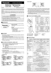
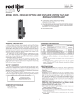
Drawing No. LP0909A
Effective 07/13
Tel +1 (717) 767-6511
Fax +1 (717) 764-0839
www.redlion.net
GRAPHITE SERIES
10" Color Touchscreen Operator Interface
Installation Guide
SPECIFICATIONS
See the Red Lion website at www.redlion.net or the enclosed
USB thumbdrive for full user manual, Crimson software and
software manual.
POWER: +24 VDC ±20%
G10C/RG10S
Typical Power HMI only:
12 W
18 W
Maximum Power HMI only: 19 W
24 W
HMI With Module(s):
48W
53 W
Must use a Class 2 circuit according to National Electrical Code (NEC),
NFPA-70 or Canadian Electrical Code (CEC), Part I, C22.1 or a Limited
Power Supply (LPS) according to IEC 60950-1 or Limited-energy circuit
according to IEC 61010-1.
Power connection via removable three position terminal block.
ENVIRONMENTAL CONDITIONS:
Operating Temperature Range: -20 to 60 °C
Storage Temperature Range: -20 to 70 °C
Vibration to IEC 68-2-6: Operational 5-300 Hz, 3 g
Shock to IEC 68-2-27: Operational 40 g
Operating and Storage Humidity: 0 to 85% max. RH non-condensing
Altitude: Up to 2000 meters
CERTIFICATIONS AND COMPLIANCES:
CE Approved
EN 61326-1 Immunity to Industrial Locations
Emission CISPR 11 Class A
IEC/EN 61010-1
RoHS Compliant
Type 4X Indoor / IP66 Enclosure rating (Face only) for all models
Type 4X Outdoor Enclosure rating (Face only) for G10Sxxxx models
CONNECTIONS: High compression cage-clamp terminal block
Wire Strip Length: 0.3" (7.5 mm)
Wire Gauge Capacity: One 14 AWG (2.55 mm) solid,
two 18 AWG (1.02 mm) or four 20 AWG (0.61 mm)
CONSTRUCTION: Cast aluminum enclosure with NEMA 4X/IP66 rating for
indoor use only when correctly fitted with the gasket provided. Installation
Category II, Pollution Degree 2.
WEIGHT: 4.8 lb. (2.18 Kg)
SAFETY SUMMARY
All safety related regulations, local codes and instructions that appear in this
literature or on equipment must be observed to ensure personal safety and to
prevent damage to either the instrument or equipment connected to it. If
equipment is used in a manner not specified by the manufacturer, the protection
provided by the equipment may be impaired. Do not use this unit to directly
command motors, valves, or other actuators not equipped with safeguards. To
do so can be potentially harmful to persons or equipment in the event of a fault
to the unit.
CAUTION: Risk of Danger.
Read complete instructions prior to
installation and operation of the unit.
CAUTION:
Risk of electric shock.
ORDERING INFORMATION
DESCRIPTION
PART NUMBER
10" color touch screen, indoor use, 24 VDC powered
G10C0000
10" color touch screen, indoor use, 24 VDC powered,
additional ethernet port
G10C1000
10" high resolution display, color touch screen, indoor use,
24 VDC powered
G10R0000
10" high resolution display, color touch screen, indoor use,
24 VDC powered, additional ethernet port
G10R1000
10" color touch screen, indoor/outdoor use, 24 VDC powered
G10S0000
10" color touch screen, indoor/outdoor use, 24 VDC powered,
additional ethernet port
G10S1000
DIMENSIONS In inches (mm)
10.84 (275.2)
2.06 (52.4)
11.1 (281)
2.97 (76)
8.57
(217.7)
8.8
(224)
Module sold
separately
(MOUNTING CLIPS INSTALLED)
1
Operator Interface Installation
MOUNTING INSTRUCTIONS
CONNECTING TO EARTH GROUND
The protective conductor terminal is bonded to conductive
parts of the equipment for safety purposes and must be
connected to an external protective earthing system.
FOOT MAY BE REMOVED
FOR THICKER PANEL
INSTALLATIONS
Each operator panel has a chassis ground terminal on the back of the unit.
Your unit should be connected to earth ground (protective earth).
The chassis ground is not connected to signal common of the unit.
Maintaining isolation between earth ground and signal common is not required
to operate your unit. But, other equipment connected to this unit may require
isolation between signal common and earth ground. To maintain isolation
between signal common and earth ground care must be taken when connections
are made to the unit. For example, a power supply with isolation between its
signal common and earth ground must be used. Also, plugging in a USB cable
may connect signal common and earth ground.1
1
USB’s shield may be connected to earth ground at the host. USB’s shield in
turn may also be connected to signal common.
This operator interface is primarily designed for throughpanel mounting. Four VESA mount tapped screw-holes (M4
x 0.7, 5 mm deep) are present on the rear of the panels to
allow for stand or wall mounting. Care should be taken to
remove any loose material from the mounting cut-out to
prevent that material from falling into the operator interface
during installation. A gasket is provided to enable sealing to
NEMA 4X/IP66 specification. Install the nine mounting
clips provided and tighten to 6.0 pound-force inch (96
ounce-force inch) evenly for uniform gasket compression.
POWER SUPPLY REQUIREMENTS
ALL NONINCENDIVE CIRCUITS MUST BE
WIRED USING DIVISION 2 WIRING
METHODS AS SPECIFIED IN ARTICLE 501-4
(b), 502-4 (b), AND 503-3 (b) OF THE
NATIONAL ELECTRICAL CODE, NFPA 70
FOR INSTALLATION WITHIN THE UNITED
STATES, OR AS SPECIFIED IN SECTION
19-152 OF CANADIAN ELECTRICAL CODE
FOR INSTALLATION IN CANADA.
The G10 requires a 24 VDC power supply. Your unit may draw considerably
less than the maximum rated power depending upon the features being used. As
additional features are used your unit will draw increasing amounts of power.
Items that could cause increases in current are modules, additional on-board
communications, SD card, and other features programmed through Crimson.
In any case, it is very important that the power supply is mounted correctly if
the unit is to operate reliably. Please take care to observe the following points:
– The power supply must be mounted close to the unit, with usually not more
than 6 feet (1.8 m) of cable between the supply and the operator interface.
Ideally, the shortest length possible should be used.
– The wire used to connect the operator interface’s power supply should be
at least 22-gage wire. If a longer cable run is used, a heavier gage wire
should be used. The routing of the cable should be kept away from large
contactors, inverters, and other devices which may generate significant
electrical noise.
– A power supply with an NEC Class 2 or Limited Power Source (LPS) and
SELV rating is to be used. This type of power supply provides isolation to
accessible circuits from hazardous voltage levels generated by a mains
power supply due to single faults. SELV is an acronym for “safety extralow voltage.” Safety extra-low voltage circuits shall exhibit voltages safe
to touch both under normal operating conditions and after a single fault,
such as a breakdown of a layer of basic insulation or after the failure of a
single component has occurred.
PANEL CUT-OUT
10.197 (259.0)
4X R.10 (2.5)
MAX.
7.931
(201.4)
All tolerances ±.059" (±1.5 mm)
I/O MODULE INSTALLATION
Modules must be installed beginning with slot 1 (left-most slot), with no
empty slots between the modules, and the order must match the modules order
in the Crimson database. Torque screws to 6.0 pound-force inch (96 ounceforce inch).
VESA MOUNT (MIS-D 75) DIMENSIONS
1.48 (37.5)
2.95
(75)
2.95 (75)
.87
(22.1)
REMOVE RUBBER
MODULE PLUG
WARNING: Disconnect all power
to the unit before installing or
removing modules.
2
Communicating With
the
CONFIGURING A G10
G10
INSERTION/REMOVAL OF THE SD CARD
The G10 is configured using Crimson® software. Crimson is available as a
free download from Red Lion’s website. Updates to Crimson for new features
and drivers are posted on the website as they become available. By configuring
the G10 using the latest version of Crimson, you are assured that your unit has
the most up to date feature set. Crimson® software can configure the G10 through
the RS232 PGM port, USB port, or SD.
The USB port is connected using a standard USB cable with a Type B
connector. The driver needed to use the USB port will be installed with Crimson.
The RS232 PGM port uses a programming cable made by Red Lion to connect
to the DB9 COM port of your computer. If you choose to make your own cable,
use the “G10 Port Pin Out Diagram” for wiring information.
The SD can be used to program a G10 by placing a configuration file and
firmware on the SD card. The card is then inserted into the target G10 and
powered. Refer to the Crimson literature for more information on the proper
names and locations of the files.
Insert the SD card into the slot provided with the card oriented as shown. The
card is inserted properly when the end of the card is flush with the Graphite
case. To remove the SD card, push in slightly on the card.
USB, DATA TRANSFERS FROM THE SD CARD
WARNING - DO NOT CONNECT OR DISCONNECT CABLES
WHILE POWER IS APPLIED UNLESS AREA IS KNOWN TO BE
NON-HAZARDOUS. USB PORT IS FOR SYSTEM SET-UP AND
DIAGNOSTICS AND IS NOT INTENDED FOR PERMANENT
CONNECTION.
In order to transfer data from the SD card via the USB port, a driver must be
installed on your computer. This driver is installed with Crimson and is located
in the folder C:\Program Files\Red Lion Controls\Crimson 3.0\Device\ after
Crimson is installed. This may have already been accomplished if your G10 was
configured using the USB port.
Once the driver is installed, connect the G10 to your PC with a USB cable,
and follow “Mounting the SD” instructions in the Crimson 3 user manual.
G10 PORT PIN OUTS
AUXILIARY
ETHERNET
(NIC)
[OPTIONAL]
USB HOST
ETHERNET
(NIC)
STATUS
USB
TYPE B
STATUS
PORT B
POWER
CONNECTOR
RS232
PORT A (PGM)
RS485
PORT A
RS232
PGM PORT
3
RS232
PORT B
RTS (PIN 6)
Tx
COMM
COMM
Rx
CTS (PIN 1)
ETHERNET
TxA (PIN 8)
TxB
COMM
TxEN
RxB
RxA
TxA
TxB (PIN 1)
USB HOST
RTS (PIN 6)
Tx
COMM
COMM
Rx
CTS (PIN 1)
AUXILIARY
ETHERNET
USB
DEVICE
PORT A
3 CHASSIS
2 +DC VOLTAGE
1 COMMON
POWER
- +
RS485
RS232
COMMS PORT COMMS PORT
BATTERY & TIME KEEPING
WARNING - EXPLOSION HAZARD - THE AREA MUST BE
KNOWN TO BE NON-HAZARDOUS BEFORE SERVICING/
REPLACING THE UNIT AND BEFORE INSTALLING OR
REMOVING I/O WIRING AND BATTERY.
WARNING - EXPLOSION HAZARD - DO NOT DISCONNECT
EQUIPMENT UNLESS POWER HAS BEEN DISCONNECTED
AND THE AREA IS KNOWN TO BE NON-HAZARDOUS.
-
A battery is used to keep time when the unit is without power. Typical
accuracy (at 25°C) of the Graphite time keeping is less than one minute per
month drift. The battery of a Graphite unit does not affect the unit’s memory, all
configurations and data is stored in non-volatile memory.
+
Changing the Battery
To change the battery of a Graphite, first remove power to the unit. Remove
the battery cover. Grasp the top edge of the battery and push to the left to remove
the battery from the holder. Lift the battery out and replace with a new battery.
Replace the battery cover, and re-apply power. Using Crimson or the unit’s
keypad, enter the correct time and date.
* Please note that the old battery must be disposed of in a manner that
complies with your local waste regulations. The battery must not be disposed of
in fire, or in a manner whereby it may be damaged and its contents could come
into contact with human skin.
The battery used by the panel is a lithium type BR2032.
LIMITED WARRANTY
The Company warrants the products it manufactures against defects in materials and
workmanship for a period limited to two years from the date of shipment, provided
the products have been stored, handled, installed, and used under proper conditions.
The Company’s liability under this limited warranty shall extend only to the repair or
replacement of a defective product, at The Company’s option. The Company disclaims
all liability for any affirmation, promise or representation with respect to the products.
The customer agrees to hold Red Lion Controls harmless from, defend, and indemnify
RLC against damages, claims, and expenses arising out of subsequent sales of RLC
products or products containing components manufactured by RLC and based upon
personal injuries, deaths, property damage, lost profits, and other matters which Buyer,
its employees, or sub-contractors are or may be to any extent liable, including without
limitation penalties imposed by the Consumer Product Safety Act (P.L. 92-573) and
liability imposed upon any person pursuant to the Magnuson-Moss Warranty Act (P.L.
93-637), as now in effect or as amended hereafter.
No warranties expressed or implied are created with respect to The Company’s products
except those expressly contained herein. The Customer acknowledges the disclaimers
and limitations contained herein and relies on no other warranties or affirmations.
20 Willow Springs Circle | York, PA 17406 USA
+1 (717) 767-6511 | [email protected] | www.redlion.net
4