1
The audio data writing procedure.
ML610Q346
November 29, 2011
© 2011 LAPIS Semiconductor Co., Ltd. All Rights Reserved
Index
The arrangement of the ML610Q346 audio data.
The audio data writing procedure.
Overview
1. Audio data making and save.
2. Writes an audio data to MCU.
3. The audio data save by the DTU8 (Debugger).
4. The audio data write by the DTU8 (Debugger).
5. Generate "the ROM image data" by the HTU8.
5-1. Convert ABS file to the HEX
5-2. Generate “the ROM code data” from “the HEX data and the
audio data” by HTU8.
5-3. The writing in of the ROM code data
© 2011 LAPIS Semiconductor Co., Ltd. All Rights Reserved
2
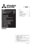
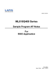
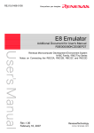
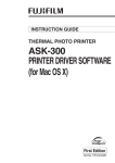
The arrangement of the ML610Q346 audio data.
Address of audio data file. Memory address of ML610Q346
0x00000 - 0x0FFFF
0x10000 - 0x1FFFF(1)
0x10000 - 0x1XXXX
The free space of segment0 0x0YYYY - 0x0FBFF
*The start address of segment0 is setting by initialize function of speech library.
Audio data file
0x00000
It arranges in
segment1.
Memory of ML610Q346
Program code 0x00000
area.
0x0YYYY
0x0FFFF
0x10000 It arranges in
segment0.
Segment0
0x0FBFF
Test data area.
0x1XXXX
0x0FFFF
0x10000
Segment1
0x1FFFF
© 2011 LAPIS Semiconductor Co., Ltd. All Rights Reserved
3
Overview
The procedure which writes the audio data which was created in
Speech LSI Utility to MCU
• By the following order, the audio data writing procedure is explained.
( This explanation is based on ML610Q346. )
1.
Audio data making and save.
The audio data make by Speech LSI Utility and save at Motorola S format.
2. Writes an audio data to MCU.
When the first time writing, it writes by FWuEASE Flash Writer.
3. Audio data save by DTU8.
By saving in DTU8(debugger) , next time writes can be simplified.
4.
Audio data write by DTU8.
By using the data saved by the way of topic "3.", it can write in by operation
of only DTU8 the 2nd time and afterwards.
© 2011 LAPIS Semiconductor Co., Ltd. All Rights Reserved
4
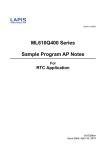
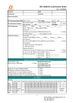
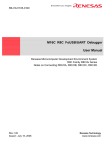
1. Audio data making and save.
•The audio data make by Speech LSI Utility and it saves a audio data by the setting of
the figure which is shown in the following.
The save-format : Save at Motorola S File format
Confirm that it is selecting this part.
© 2011 LAPIS Semiconductor Co., Ltd. All Rights Reserved
5
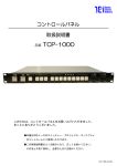
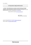
2. Writes an audio data to MCU. (1/2)
• The audio data writes to MCU by FWuEASE Flash Writer.
( The audio data to write uses the file which saved by the preceding chapter. )
<Setting for write to segment1>
After the entry completion which is shown in the following figure, it adds to the File List
by the [Add to List] button click.
With this, the setting in segment1 is completion.
Set the file which was created by Speech LSI Utility.
The beginning of the file is 0H.
Set a target LSI.
End of address of file which
write to segment1.
The beginning of the flash memory is 0H.
© 2011 LAPIS Semiconductor Co., Ltd. All Rights Reserved
6
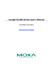
2. Writes an audio data to MCU. (2/2)
<Setting for write to segment0>
After the entry completion which is shown in the following figure, it adds to the File List by the [Add
to List] button click.
With this, the setting in segment0 is completion.
* When there is not audio data to write in segment0, you need not write audio data to segment0.
•The offset of the flash memory becomes -000CH with the following formula.
4000H – 10000H = -C000H
4000H: The audio data entry address in segment 0 (On the supposition that there is program into 0-3FFFH.)
10000H: The address immediately behind the audio data which was arranged in segment1
-C000H: Offset of flash memory address.
The setting to write audio data to MCU is completion.
It writes to flash memory by the [Write&Check] button click.
The beginning of the file is 10000H
The offset of the flash memory is -C000H.
The end address sets the last of the file.
© 2011 LAPIS Semiconductor Co., Ltd. All Rights Reserved
7
3. The audio data save by the DTU8 (Debugger).
• The audio data written in MCU by the explain of the preceding chapter,
save so that it can be used by DTU8.
By doing this, the audio data can write by DTU8 from the next time.
Save the audio data of segment1
1. It starts up DTU8 and it chooses " Save program to file " of " File menu ".
2. It enters "Start address" (10000H) and "End address" (1FFFFH) and a "File name" for segment1.
("Motorola S2 format" or "Intel HEX format" of the type of files is not a problem in the file type. It is
optional.)
3. When clicking the “Save” button after the above entry, it is saved by the specified file format.
Save the audio data of segment0
4. Following the above item 3., it enters "Start address" (4000H) and "End address" (FBFFH) and a "File
name" for segment0.
("Motorola S2 format" or "Intel HEX format" of the type of files is not a problem in the file type. It is
optional.)
5. When clicking the “Save” button after the above entry, it is saved by the specified file format.
* When there is not audio data to write in segment0, you need not save audio data to segment0.
* When on the supposition that there is program into 0-3FFFH, it makes the above start address
4000H
© 2011 LAPIS Semiconductor Co., Ltd. All Rights Reserved
8
4. The audio data write by the DTU8 (Debugger).
• The procedure which writes the audio data which saved by the preceding
chapter in MCU using DTU8 is described.
Load the audio data of segment1
1. It starts up DTU8 and it chooses " Load program to file " of " File menu ".
2. It chooses the file which saved for segment1 and it enters "Start address" (10000H) and "End
address"(1FFFFH).
3. When clicking the “Open” button after the above entry, it is written an audio data for segment1
of MUC.
Load the audio data of segment0
4. Following the above item 3., it chooses the file which saved for segment0 and it enters “Start
address” (4000H) and “End address“ (FBFFH).
5. When clicking the “Open” button after the above entry, it is written an audio data for segment1
of MUC.
* When there is not audio data to write in segment0, you need not write audio data to
segment0.
* When on the supposition that there is program into 0-3FFFH, it makes the above start
address 4000H
* When writing an audio data in the condition which a program is already written in, set
"Value of blank area" to "Contents of the Flash Memory" at entry of item 4. .
* In the same way. When writing a program after the audio data writing in DTU8, it sets
"Value of blank area" to "Contents of the Flash Memory" at entry of item 4. .
© 2011 LAPIS Semiconductor Co., Ltd. All Rights Reserved
9
5. Generate "the ROM image data" by the HTU8.
• The way of making program data and an audio data one HEX format file by HTU8
is Specified in this chapter. Moreover, are specified about the way of writing in to
ML610Q346. The data which is explained in this chapter uses the data which was
defined in the "The arrangement of the ML610Q346 audio data. (page 3)" chapter.
5-1. Convert ABS file to the HEX (1/2)
You have to convert an object file that is included the debugging information to the HEX
data that are input files of HTU8. (Here-in-after, the object file is called the ABS file.)
It shows the way to convert the ABS file to “the HEX data” as following. We recommend
setting up the following settings at the time of the beginning of program development
stage.
As shown in the figure, select [Project] [Options] [Target] from the IDEU8 menu.
© 2011 LAPIS Semiconductor Co., Ltd. All Rights Reserved
10
5-1. Convert ABS file to the HEX (2/2)
As shown in the figure, select [General] tab from [Target options] dialogue. Check on
[Create HEX file] in the [Object converter] group, select [Intel HEX] and check off [Include
debugging information].
Build your program. After the building process is finished, confirm two messages “Convert
End.”, “Finished building” are displayed in the output window as shown in the figure.
“The HEX data” will be output in the specified folder.
© 2011 LAPIS Semiconductor Co., Ltd. All Rights Reserved
11
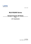
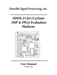
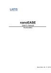
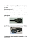
5-2. Generate “the ROM code data” from “the HEX data and the audio data" by HTU8.
(1/2)
The following figure shows the relationship of input files and ROM code data file.
(1)
* On the supposition that there
is program into 0-3FFFH
0000H
Input program file
Sample_Ver100.hex
0x00000
(3)
3FFFH
4000H
7FFFH
(2)
* On the supposition that there
is audio data into 0-13FFFH
0x0FFFF
0x10000
(1)
(2)
1:0000H
(3)
0x13FFF
Input audio file
Voice_data.s
ROMコードデータ
ML610Q346_NNNRA.hex /
ML610Q346_NNNRB.hex
NOTE) Input audio file (Voice_data.s): The file which was created at “Audio data making and save.” of chapter 1
Input program file (Sample_Ver100.hex): The file which was created at “Convert ABS file to the HEX.” of chapter 5-1.
© 2011 LAPIS Semiconductor Co., Ltd. All Rights Reserved
12
5-2. Generate “the ROM code data” from “the HEX data and the audio data" by HTU8.
(2/2)
From the Start menu, select “All programs” >”U8 Tools”>”nX-U8”>”Command-line
environment” icon to open the U8 command prompt.
On the U8 command prompt, by using CD command, move to the folder which “the complete
HEX data” is located in.
For example, if “the HEX data” is located in “C:/Test/Sample/Hex”, input the command as
follows.
Example: CD C:/Test/Sample/Hex
On the U8 command prompt, execute HTU8, please. Specified the example which used a
response file in this document. The response file is a text file which specified the input files
and the options. It is convenient when you specify multiple input files or specify complex
operation by options. The following example shows the sample of response file. It creates
this example from the input-file image of the pre-page.
// Sample of the response file (Sample.res)
Sample_Ver100.hex
voice_data.s /AL(0, 0FFFFH, 1:0000H)
voice_data.s /AL(1:0000H, 1:3FFFH, 0:4000H)
/TM610346
/FML610Q346_NNN
/OH
// Input file 1 (program file)
// Input file 2 (audio file)
// Input file 3 (audio file)
// Target
// Output file name
// Output file format
On the U8 command prompt, execute response file.
Type “HTU8 @Sample.res” and execute.
In the above example case, HTU8 generates two (2) “the ROM code data” files
(ML610Q346_NNNRA.hex, ML610Q346_NNNRB.hex) and a log file
(ML610Q346_020RA.log).
© 2011 LAPIS Semiconductor Co., Ltd. All Rights Reserved
13
5-3. The writing in of the ROM code data
Writes the ROM code data (ML610Q346_NNNRA.hex) which was created by the preceding
clause in Flash ROM.
When writing created ROM code data to Flash ROM using FwuEASE, two pieces of data must
be divided. Because, when writing in Flash ROM, it is to avoid an unused-area and to have to
be written.
It is possible to write notes easily to ignore an unused-area if using MwuEASE. It recommends
to be used in MwuEASE.
Please refer to "Multiple Flash Writer MWuEASE User's Manual" for how to use MwuEASE.
*Request MwuEASE software to attach it in case of on-chip debugger uEASE purchase.
© 2011 LAPIS Semiconductor Co., Ltd. All Rights Reserved
14