1
Phono Preamplifier for MC / MM
User’s Manual
1
2
Contents
1
Preface..........................................................................................5
1.1
Included.........................................................................................6
1.2
Transport .......................................................................................6
2
Overview front panel ..................................................................7
3
Overview back panel...................................................................8
4
Installation and power supply....................................................9
4.1
Placement ......................................................................................9
4.2
Mains connection ........................................................................10
4.3
External power supply EPS.........................................................10
5
Inputs and outputs ....................................................................12
5.1
Inputs...........................................................................................12
5.2
Outputs ........................................................................................12
6
Usage ..........................................................................................13
6.1
Powering up ................................................................................13
6.2
Switching on/off..........................................................................13
6.3
Control elements on the front panel ............................................13
6.4
Mains phase detection .................................................................14
6.5
Input selection .............................................................................14
7
Settings .......................................................................................15
7.1
Matching the pick-up's electrical characteristic ..........................15
7.1.1
MM Systems ...............................................................................16
7.1.2
MC Systems ................................................................................16
7.1.3
Typical setups .............................................................................17
7.2
Factory defaults...........................................................................17
7.3
Further adjustments.....................................................................17
7.3.1
Adjusting the input capacity .......................................................17
7.3.2
Resistance reduction ...................................................................18
8
Technical information...............................................................19
8.1
Design .........................................................................................19
8.2
Power supply...............................................................................19
3
8.3
Circuitry ......................................................................................19
9
Security advice...........................................................................20
10
Technical data............................................................................21
4
1
Preface
The Audionet Team congratulates you on your purchase of this unit.
Audionet components are no marketing products, they are authentic.
Conceived and developed with scientific inspiration, professional engineering expertise and a passion for achieving the perfect sound. They are
unique creations designed to inspire musical enjoyment and have an excellent reputation amongst all connoisseurs throughout the world. Each
and every one of our precision-manufactured devices are individually
crafted at our factory located in Bochum, Germany by our experienced
and passionate workforce.
But before you start listening to your new Audionet PAM G2, please read
this manual carefully so you are able to use and enjoy all functions of this
unit without drawback on music quality.
5
1.1 Included
Included you will find the following items:
·
the phono preamplifier PAM G2
·
the user's manual (that you are currently reading)
·
one standard mains cord
·
one green-yellow cord for an additional earth connection
1.2 Transport
Important
·
Please transport the PAM G2 only in the included package.
·
Always use the plastic bag to prevent scratches on the casing.
·
Please allow the PAM G2 to adapt to the climatic conditions in your
listening room before you switch on the unit for the first time after
transport.
6
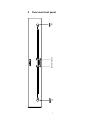
power
key
channel indicator
input
key
2
Overview front panel
7
8
Earth connectors for turntables
RCA input no. 2, left/right
RCA output, left/right
Connector for external power supply EPS
Gain (dB), input 1
2
3
4
5
6
3
RCA input no. 1, left/right
2
15
1
1
16
Mains input
9
12 Input resistance - R(Ω), input 2
11 Input capacity- C(pF), input 2
10 Marking mains phase
Input capacity - C(pF), input 1
8
5
Input resistance - R(Ω), input 1
4
7
14
6
7
12
8
9
11
10
16 RCA input for additional input resistance or
input capacitance on input 1, left/right
15 RCA input for additional input resistance or
input capacitance on input 2, left/right
14 Balanced (XLR) output, left/right
13 Gain(dB), input 2
13
3
Overview back panel
4
Installation and power supply
Important
·
During connecting and removing of turntables or preamplifiers to
the PAM G2 all units of your audio system have to be switched off to
prevent damage of the PAM G2 or any of the other connected units.
·
Please make sure that all cables are in absolute best conditions!
Broken shields or short-cut cables could damage the PAM G2
and/or any other connected unit.
4.1 Placement
Important
·
It is recommended to place the PAM G2 into a high quality rack or
onto a stable table.
·
Do not expose the unit to direct sunlight.
·
Do not cover the ventilation slots.
·
Do not place the PAM G2 in close range to heat sources like radiators.
·
Do not place the PAM G2 on top of other units, especially not on top
of power amplifiers, preamplifiers or similar that produce heat. Both
units could suffer damage from thermal overload.
·
Transformers in amplifiers and other powerful devices may create
interfering fields. Therefore, put the PAM G2 as far away as possible
from such devices.
·
Do not use the unit in places where it is exposed to vibrations.
·
Do not place the unit close to loudspeakers or into the corner of a
room where it is exposed to high levels of sonic energy, which might
reduce the sound quality of the unit.
·
If the PAM G2 is used with the external power supply EPS it is recommended to put the EPS to the right or at least 20 cm above/below
of the PAM G2. Increasing the distance of both units, will minimize
the influence of the mains transformers in the EPS.
9
4.2 Mains connection
The mains input 9 * is on the back panel of the PAM G2. To connect the
unit to mains use the included mains cord. If you prefer to use a different
power cord make sure that it meets the specifications for your home country.
Important
·
The electrical specifications of your home country must meet the
electrical specifications printed onto the back panel.
·
The PAM G2 is a Class I unit and must be earthed. Please ensure a
stable earth connection. Phase ('hot' pin) is marked on the back panel
("PHASE") 10
·
Never pull the mains plug while the PAM G2 is switched on! Before
you pull the mains cord off the socket, power down the unit to standby mode.
Only in cases of extended absence (like vacations) or if massive trouble
on the mains power is to be expected you should remove the PAM G2
form the mains. To disconnect the unit completely from mains pull the
mains plug.
Note
·
Using high-quality mains cords as the Audionet P10, may improve
the sound quality. Please consult your local Audionet dealer.
4.3
External power supply EPS
In order to use the optional external precision power supply Audionet
EPS (Enhanced Power Supply) with you PAM G2 please proceed as
follows:
1.
Make sure both PAM G2 and EPS are switched off and disconnected
from the mains.
2.
Connect the EPS with the included cable to input jack EPS 5 on the
back panel of the PAM G2. The shape of the plug prevents any
wrong polarity. Now screw the ring of the plug onto the EPS input
jack 5
3.
Connect only the EPS to the mains.
4.
First, switch on the EPS on its back panel.
*
see numbers in section 'Overview back panel' on page 8.
10
5.
Use the power key on the front panel to switch on the PAM G2. The
PAM G2 is now ready to use and gets its power from the external
power supply EPS.
6.
To switch off the PAM G2 into stand-by mode, use the power key
on the front panel
Important
·
Use only EPS G2 devices (with serial number 12.21.10 or higher) if
your PAM G2 is powered by the optional external power supply.
Noncompliance may cause damage to both units.
Tip
·
Place the external power supply EPS to the right or at least 20 cm
above/below of the PAM G2. Increasing the distance of both units,
will minimize the influence of the mains transformers in the EPS.
·
Use a high quality cable (for example the Audionet P10) to connect
the EPS to mains. The sound will improve.
Important
·
Never switch on or off the EPS on its back panel while the PAM G2
is operating.
·
For further information referring to the external power supply EPS
please consult its user's manual.
11
5
Inputs and outputs
Important
·
During connecting and removing of turntables or preamplifiers to
the PAM G2 all units of your audio system have to be switched off to
prevent damage of the PAM G2 or any of the other connected units.
·
Please make sure that all cables are in absolute best conditions!
Broken shields or short-cut cables could damage the PAM G2
and/or any other connected unit.
5.1 Inputs
The PAM G2 has two stereo line inputs 1 and 3 to connect two pickup arms or turntables. The maximal adjustable input capacity is 420 pF
and the minimal adjustable input resistance is 100 Ω. If other values are
needed to meet the electrical characteristic of the pick up, the RCA sockets C/R ext. 15 and 16 can be used to add external resistors or capacitors (see section "Further adjustments" on page 17).
The gold plated screws (GND) 2 are for connecting the turntable
grounds.
Note
·
The PAM G2 is optionally available with one or two input channels.
Depending on the model, one or two pick-up arms or turntables can
be connected.
5.2 Outputs
The PAM G2 is equipped with one RCA output LINE 4 as well as one
balanced (XLR) output BALANCED 14 for the left and right channel to
connect the unit to your preamplifier.
Use the RCA output LINE 4 to connect the PAM G2 to your preamplifier using high quality interconnectors (e.g. Audionet C100). Alternatively, you may connect the preamplifier using the balanced (XLR)
outputs BALANCED 14 in case your preamplifier does not support RCA
(line) inputs.
12
6
Usage
6.1 Powering up
First of all, please make sure your PAM G2 is connected correctly to your
turntable, preamplifier and mains (see section "Installation and power
supply" on page 9 and section "Inputs and outputs" on page 12).
The PAM G2 is a stand-by unit. As soon as the amplifier is connected to the mains, the unit is in stand-by mode
Only in cases of extended absence (like vacations) or if massive trouble
on the mains power is to be expected it is recommended to disconnect the
PAM G2 from mains.
Important
·
Never pull the mains cord while the PAM G2 is switched on! Before you pull the mains plug, power down the unit to stand-by
mode first.
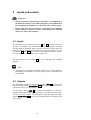
6.2 Switching on/off
To power up the PAM G2 from stand-by mode, press the power key on
the front panel. Now the PAM G2 is in normal operating mode.
If you would like to switch off the unit, please press the power key on the
front panel.
6.3 Control elements on the front panel
The front panel has two keys to control the PAM G2 (see section
"Overview front panel" on page 7).
power
Use this key to switch on/off the unit.
input
Push this key to select the input channel.
Important
·
If your PAM G2 is equipped with only one channel, the input key is
disabled and channel switching is not possible. In this case, only Input 1 is available.
13
6.4
Mains phase detection
The correct polarization of mains is important for reasons of audio clarity
and stability. Please connect the mains cord that the 'hot' pin of the wall
outlet is connected to the pin marked 'phase' 10 of the mains input 9 on
the back panel. The PAM G2 recognizes the incorrect polarization of the
mains plug automatically. After pressing the power key, the two LEDs
on the front panel will flash in different rhythms:
·
If the polarization is correct, the LEDs flash slowly: Ä___Ä___Ä ...
·
If you see the LEDs flashing rapidly: Ä_Ä_Ä_Ä_Ä… please switch
off the unit and flip the mains plug. If you now switch on the
PAM G2 again, the unit should show the correct mains polarization
by a slowly flashing LEDs.
Important
·
If the PAM G2 issues the mains polarization warning or no warning
at all for both positions of the mains plug, check the connection to
earth of your mains socket and mains cord. You have to ensure a
stable connection to earth for the mains phase detection of the
PAM G2 to work correctly!
6.5
Input selection
Push the input key on the front (see section "Overview front panel" on
page 7) to select the desired input channel. Depending on the selected
input channel, the corresponding LED on the front panel is activated.
Important
·
If your PAM G2 is equipped with only one channel, the input key is
disabled and channel switching is not possible. In this case, only Input 1 is available.
14
7
Settings
7.1
Matching the pick-up's electrical characteristic
At the back of the PAM G2 (see section: "Overview back panel" on page
8) are six rotary switches for the basic configuration of both input channels. The lower row is for the configuration of input 1, the upper row is
for the configuration of input 2.
The next section covers the configuration of input 1, the setup of input 2
is the same with the rotary switch in the upper row.
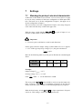
With the rotary switch labelled Gain (dB) 6 the gain of input 1 is selected to 38 dB, 48 dB, 58 dB or 68 dB.
Important
·
Excessive gain could lead to overdrive and distortion!
Set the gain so that the output voltage of the PAM G2 UPAMG2 is approx.
1...1.5 V. With a given pick-up voltage Upick-up the gain calculates to:
U PAMG2
U pickup
= gain .
Refer to the following table to get the gain in dB from the calculated gain
factor:
Gain in dB
38
48
58
68
Gain factor
80
250
800
2500
Example:
Output voltage: UPAMG2 = 1.2 V
Pick-up voltage: Upick-up = 1.5 mV
Gain:
1.2V
1.5 mV
= 800 Þ set the PAM G2 to 58 dB
The rotary switch R (Ω) 7 in the middle is used to set up the input resistance of input 1, which acts as terminating resistance of the pick-up.
Please select this value carefully; it will affect high frequency response.
With the third rotary switch C (pF) 8 the input capacitance of input 1
can be set. This setting is critical for MM systems only.
15
Note
·
If other values are needed to adjust the electrical characteristic of the
pick up, the RCA inputs C/R ext. 15 and 16 can be used to add external resistors or capacitors (see section "Further adjustments" on
page 17).
Tip
·
On our website www.audionet.de you will find an online tool to calculate the optimum settings of the PAM G2 for your pick-up.
·
If you have the specifications of your pick-up not available, you will
probably find the technical data at the following website:
www.vinylengine.com/cartridge_database.php
7.1.1
MM Systems
For MM pick-up systems set the gain to 38 dB. For the settings of input
resistance and capacitance please refer to the recommendations of the
manufacturer of your pick-up.
In case you have no recommendations from the manufacturer for input
resistance and capacitance we recommend the values 47 kW and 200 pF.
These settings offer suitable conditions for most MM pick-up systems.
7.1.2
MC Systems
MC pick-up systems cover a great range of different output levels. To
achieve an output matching the level of your other sources, the PAM G2
offers 4 gain settings:
For pick-ups with a 'normal' output level (approx. 1...2 mV output voltage) set the Gain (dB) 6 to 58 dB. For high output pick-ups (3...5 mV)
position 48 dB is better suited. In case you have a low output pick-up
(<0.8 mV) set the gain to 68 dB. In case of doubt assume your pick-up
working at a 'normal' output level.
For MC pick-up systems the input capacitance should be set to 100 pF.
Select the input resistance recommended by the manufacturer or, if the
information is not available, select position 100 W.
16
7.1.3
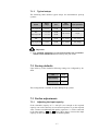
Typical setups
The following table outlines typical setups for miscellaneous pick-up
systems:
System
Output
voltage
Gain
Input
resistance
Input capacitance
Low Output MC
< 0.6 mV
68 dB
100 W
110 pF
MC
~ 1...2 mV
58 dB
High Output MC
~ 3...5 mV
48 dB
100...470 W
110 pF
MM
~ 4...6 mV
48 dB
47...68 kW
160...220 pF
High Output MM
> 6 mV
38 dB
47...68 kW
160...220 pF
Important
·
For optimum adjustment to your pick-up follow the recommendations of the manufacturer! If necessary ask your dealer.
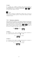
7.2 Factory defaults
Upon delivery of the PAM G2 following settings are configured by default:
Gain
38 dB
Input resistance
47 kW
Input capacitance
200 pF
This configuration is suitable for most MM pick-up systems.
7.3 Further adjustments
7.3.1
Adjusting the input capacity
If the selectable capacity of C0 = 420 pF is not enough or the required
capacity can not be selected, use an external capacitor to get the required
value. Connect an additional high quality capacitor Cext can be connected
to the input C/R ext. 15 and 16 using a RCA plug to increase the input
capacity. In this case the capacities are added together.
17
Example:
If a capacity of C = 500 pF is needed, select the base capacity of
C0 = 420 pF with the rotary switch on the back panel. Then add an additional capacitor of CEXT. = 82 pF to the input C/R ext. 15 or 16 to get
the required input capacity of 500 pF.
Note
In the above example the arithmetically resulting value of 80 pF was
replaced with the suitable capacitor of 82 pF from commonly available
standard E12 series.
7.3.2
Resistance reduction
If the required input resistance is less than the minimum selectable base
resistance of R0 = 100 Ω or the needed resistance value is not available,
use an external resistor to get the required value. Connect an additional
high quality resistor Rext to the input C/R ext. 15 and 16 using a RCA
plug to reduce the input resistance. Attention! The reciprocal values of
the resistors are added, so the input resistance is reduced!
R=
R0 * Rext
1
Þ Rext =
1 1
R0 + Rext
R R0
Example 1:
If a resistance of R = 33 Ω is needed; choose the base resistance to
R0 = 100 Ω, and add external resistor of Rext = 50 Ω.
Rext =
1
W = 50 W
1
1
33 100
Example 2:
If a resistance of R = 200 Ω is needed; choose the base resistance to
R0 = 330 Ω, and add external resistor of Rext = 510 Ω.
Rext =
1
1
1
200 330
18
W = 510 W
8
Technical information
8.1 Design
The construction is optimized magnetically and capacitatively. The signal
paths have absolute minimum lengths with no harmful components like
coupling capacitors, coils or relays. Input and output circuits are immune
to negative influences of connected devices. Consequently, SMD miniature technology ensures optimized high frequency properties.
Gain and RIAA de-emphasis are carried out simultaneously in two stages.
The operational amplifiers in the signal path are built up as discrete and
optimized elements; they have a gain-bandwidth product of 1 GHz. The
output operational amplifiers work in class “A” mode with a high bias
current.
8.2
Power supply
All voltages are delivered by a 100 VA toroid core transformer and fast,
impulse-stable audio high-current capacitors with a total capacity of
40,000 uF. The voltages are stabilized by 14 discrete and optimized MOS
regulators.
8.3
Circuitry
Every operational amplifier is supplied by two fast, discrete voltage regulators. The amplification and input stages are switched by gold-coated
precision relays. Special input impedances can be set individually.
19
9
Security advice
Important
·
Use only EPS G2 devices (with serial number 12.21.10 or higher) if
your PAM G2 is powered by the optional external power supply.
Noncompliance may cause damage to both units.
·
Avoid packaging material, especially plastic bags, coming into children's hands!
·
Store and operate the unit in a dry room at a reasonable room temperature only!
·
Avoid moisture, any liquids, dirt or small objects getting into the
unit!
·
Set up the unit in a sufficiently ventilated environment!
·
Do not cover the unit!
·
Do not open the unit. Unauthorised opening will void warranty!
·
Do not short-circuit the outputs!
·
During connecting or removing the PAM G2 to/from sources and/or
power amplifiers all units have to be switched off to prevent damage
of the PAM G2 or any of the other connected units.
·
Use dry cloth for cleaning!
20
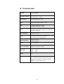
10 Technical data
Function
phono preamplifier
Frequency response
40 – 30.000 Hz (+/- 0.2dB)
18 – 80.000 Hz (+/- 1.0dB)
Subsonic filter
4nd order high pass fg = 8 Hz
Gain
38 dB, 48 dB, 58 dB, 68 dB (@ 1 kHz)
SNR
< -103 dB @ 1 kHz (Gain = 38 dB)
< -83 dB @ 1 kHz (Gain = 58 dB)
Inputs
2 pair WBT RCA jacks, gold plated
2 pair WBT RCA jackss, gold plated, for additional
impedance adjustment
Input impedance
selectable at the rear
Output
1 pair WBT-NextGen line, gold plated
1 pair XLR (Neutrik) , gold plated
Output impedance
24 Ohm real (RCA)
94 Ohm real (XLR)
Mains
230 V, 50..60 Hz
Power consumption
Stand-by < 0.5W, max. 40 Watt
Dimensions
Width: 430 mm
Height: 70 mm
Depth: 310 mm
Weight
9 kg
Finish
Front: : brushed aluminium, black anodised, white
print or aluminium 'nature', anodised, black print
Top cover: brushed aluminium, black anodised
Chassis: steel, black coated, 2 mm
21
Features
-
individual adjustment to any pick-up without
opening
-
active dual stage RIAA de-emphasis
-
no integrated operational amplifiers or capacities
in signal path
-
14 fast, purely discrete realized MOS voltage
regulators providing accumulator-like characteristics of power supply
-
100 VA toroid transformer, shielded, 40.000 µF
capacity
-
Class A output stage
-
DC-free outputs
-
FET inputs, no bias current
Errors and omissions excepted. Specifications and design are subject to changes without prior notice.
audionet is a trademark of Idektron GmbH & Co KG
Engineered and produced by:
Idektron GmbH & Co. KG, Herner Str. 299, Gebäude 6, 44809 Bochum, Germany
www.audionet.de
[email protected]
22