1
Thermo Scientific
Versette ControlMate
™
User Manual
110762 Revision B
Part of Thermo Fisher Scientific, Inc.
18 Oct. 2012
®
© 2012 Thermo Fisher Scientific Inc.. All rights reserved. Reproduction of the accompanying user
documentation in whole or in part is prohibited.
TRADEMARKS
ControlMate®, D.A.R.Ts®, and Versette™ are trademarks of Thermo Fisher Scientific Inc. and its subsidiaries.
Microsoft® and Windows® are registered trademarks of Microsoft Corporation in the United States and other
countries.
All other trademarks and registered trademarks are the property of their respective holders.
DISCLAIMER
Thermo Fisher Scientific Inc. provides this document to its customers with a product purchase to use in the
product operation. This document is copyright protected and any reproduction of the whole or any part of this
document is strictly prohibited, except with the written authorization of Thermo Fisher Scientific Inc.
The contents of this document are subject to change without notice. All technical information in this
document is for reference purposes only. System configurations and specifications in this document supersede
all previous information received by the purchaser.
Thermo Fisher Scientific Inc. makes no representations that this document is complete, accurate or errorfree and assumes no responsibility and will not be liable for any errors, omissions, damage or loss that might
result from any use of this document, even if the information in the document is followed properly.
This document is not part of any sales contract between Thermo Fisher Scientific Inc. and a purchaser. This
document shall in no way govern or modify any Terms and Conditions of Sale, which Terms and Conditions of
Sale shall govern all conflicting information between the two documents.
Revised Oct. 2012
For Research Use Only. Not for use in diagnostic procedures.
Contents
About this User Manual. . . . . . . . . . . . . . . . . . . . . . . . . . . . . . . . . . . . . . . . . . . . . . . . .3
Intended use . . . . . . . . . . . . . . . . . . . . . . . . . . . . . . . . . . . . . . . . . . . . . . . . . . . . 3
Intended users. . . . . . . . . . . . . . . . . . . . . . . . . . . . . . . . . . . . . . . . . . . . . . . . . . . 3
How to use this user’s manual. . . . . . . . . . . . . . . . . . . . . . . . . . . . . . . . . . . . . . . 3
Related Documentation . . . . . . . . . . . . . . . . . . . . . . . . . . . . . . . . . . . . . . . . . . . 4
Contacting Us . . . . . . . . . . . . . . . . . . . . . . . . . . . . . . . . . . . . . . . . . . . . . . . . . . 4
Safety and Special Notices . . . . . . . . . . . . . . . . . . . . . . . . . . . . . . . . . . . . . . . . . 4
Safety symbols and markings . . . . . . . . . . . . . . . . . . . . . . . . . . . . . . . . . . . . . . . 4
Thermo Scientific
Chapter 1
Introduction . . . . . . . . . . . . . . . . . . . . . . . . . . . . . . . . . . . . . . . . . . . . . . . . . . . . . . . . . . 11
General Description . . . . . . . . . . . . . . . . . . . . . . . . . . . . . . . . . . . . . . . . . . . . . 11
Chapter 2
Installation . . . . . . . . . . . . . . . . . . . . . . . . . . . . . . . . . . . . . . . . . . . . . . . . . . . . . . . . . . . 13
Minimum System Requirements . . . . . . . . . . . . . . . . . . . . . . . . . . . . . . . . . . . . 13
Installing ControlMate . . . . . . . . . . . . . . . . . . . . . . . . . . . . . . . . . . . . . . . . . . . 16
Chapter 3
Configuring ControlMate . . . . . . . . . . . . . . . . . . . . . . . . . . . . . . . . . . . . . . . . . . . . . . . 21
Connecting to a Versette System . . . . . . . . . . . . . . . . . . . . . . . . . . . . . . . . . . . . 21
Verify Versette System Setup. . . . . . . . . . . . . . . . . . . . . . . . . . . . . . . . . . . . . . . 25
Chapter 4
Calibration . . . . . . . . . . . . . . . . . . . . . . . . . . . . . . . . . . . . . . . . . . . . . . . . . . . . . . . . . . . 27
Calibrating the System Coordinates. . . . . . . . . . . . . . . . . . . . . . . . . . . . . . . . . . 27
Versette System Calibration Flowchart . . . . . . . . . . . . . . . . . . . . . . . . . . . . . . . 28
Required Equipment . . . . . . . . . . . . . . . . . . . . . . . . . . . . . . . . . . . . . . . . . . . . . 28
STEP 1: Verify Communications with the Versette System. . . . . . . . . . . . . . . . 29
STEP 2: Verify Versette System Setup. . . . . . . . . . . . . . . . . . . . . . . . . . . . . . . . 33
STEP 3: Install the NTC Pipetting Module and NTC Teach Tool. . . . . . . . . . 34
STEP 4: Calibrate Stage XY Coordinates. . . . . . . . . . . . . . . . . . . . . . . . . . . . . . 43
STEP 5: Calibrate the Z-axis . . . . . . . . . . . . . . . . . . . . . . . . . . . . . . . . . . . . . . . 49
STEP 6: Calibrate Reagent Reservoir Fill Sensor . . . . . . . . . . . . . . . . . . . . . . . . 52
STEP 7: Optimizing Additional Stage Positions . . . . . . . . . . . . . . . . . . . . . . . . 55
Saving, Recalling, and Backing Up Calibrated Data . . . . . . . . . . . . . . . . . . . . . 62
Chapter 5
Labware Library. . . . . . . . . . . . . . . . . . . . . . . . . . . . . . . . . . . . . . . . . . . . . . . . . . . . . . . 67
Editing/Entering Labware Items . . . . . . . . . . . . . . . . . . . . . . . . . . . . . . . . . . . . 67
Chapter 6
Creating Pipetting Programs. . . . . . . . . . . . . . . . . . . . . . . . . . . . . . . . . . . . . . . . . . . 105
Creating Sequences . . . . . . . . . . . . . . . . . . . . . . . . . . . . . . . . . . . . . . . . . . . . . 106
Commands: Summary. . . . . . . . . . . . . . . . . . . . . . . . . . . . . . . . . . . . . . . . . . . 109
Advanced Protocol Creation Options, Commands, and Controls . . . . . . . . . . 134
Sequence File Editor . . . . . . . . . . . . . . . . . . . . . . . . . . . . . . . . . . . . . . . . . . . . 159
Validating a Sequence . . . . . . . . . . . . . . . . . . . . . . . . . . . . . . . . . . . . . . . . . . . 161
Chapter 7
Sample Pipetting Sequences . . . . . . . . . . . . . . . . . . . . . . . . . . . . . . . . . . . . . . . . . . 163
Example Sequence 1: Basic Aspirate and Dispense. . . . . . . . . . . . . . . . . . . . . . 164
Versette ControlMate User Manual Rev. B
1
Contents
Example Sequence 2: 8/96 Serial Dilute . . . . . . . . . . . . . . . . . . . . . . . . . . . . . 170
Example Sequence 3: 96/384 Serial Dilute . . . . . . . . . . . . . . . . . . . . . . . . . . . 181
Example Sequence 4: Plate Reformatting. . . . . . . . . . . . . . . . . . . . . . . . . . . . . 190
Example Sequence 5: Plate Reformatting with Global Variable . . . . . . . . . . . . 211
Example Sequence 6: Use of Multiple Global Variables. . . . . . . . . . . . . . . . . . 220
Chapter 8
Advanced Functions and Techniques . . . . . . . . . . . . . . . . . . . . . . . . . . . . . . . . . . . 257
Pipetting Techniques for Small Volumes. . . . . . . . . . . . . . . . . . . . . . . . . . . . . 257
Volumetric Calibration . . . . . . . . . . . . . . . . . . . . . . . . . . . . . . . . . . . . . . . . . . 259
Glossary . . . . . . . . . . . . . . . . . . . . . . . . . . . . . . . . . . . . . . . . . . . . . . . . . . . . . . . . . . . .265
Index . . . . . . . . . . . . . . . . . . . . . . . . . . . . . . . . . . . . . . . . . . . . . . . . . . . . . . . . . . . . . . .269
2
Versette ControlMate User Manual Rev. B
Thermo Scientific
P
About this User Manual
The Thermo Scientific Versette™ system is a versatile automated microplate and tube
pipetting system designed to meet the demands of life science/research liquid manipulation at
all stages and rates of production. This guide describes the installation setup, operation, and
routine use of the ControlMate software for Versette. Refer to the Versette User Manual for
complete details on the installation and operation of the Versette system.
Intended use
The Versette system is intended for professional research use by trained personnel. The
instrument is intended for automated microplate and tube pipetting. Use for diagnostic
testing is excluded. It is recommended that Good Laboratory Practice (GLP) is followed to
guarantee reliable analyses.
Intended users
This user manual is written for the end user, for example, research scientist or laboratory
technician, and provides information on the use of ControlMate software for the Versette
system. The Versette system is intended for use by persons who have been trained on standard
laboratory and equipment safety and use.
Read this manual in its entirety before operating the instrument.
How to use this user’s manual
This user manual is designed to give you the information to:
• Install the ControlMate software
• Calibrate theVersette system
• Understanding the Eprompts/Icons
• Perform sample sequences
• Optimize the instrument performance
Thermo Scientific
Versette ControlMate User Manual Rev. B
3
Preface
Related Documentation
Related Documentation
In addition to this guide, Thermo Scientific provides the following documents for the
Versette system:
• Versette User Manual
Contacting Us
For the latest information on products and services, visit our website at:
http://www.thermoscientific.com
Safety and Special Notices
Make sure you follow the precautionary statements presented in this guide and in the Versette
User Manual. The safety and other special notices appear in boxes. Thermo Fisher Scientific
and any of its agents, affiliates, subsidiaries, or other relations, direct or casual, will not be held
responsible for a user’s failure to comply with safety devices and practices.
Safety and special notices include the following:
CAUTION Highlights hazards to humans, property, or the environment. Each CAUTION
notice is accompanied by an appropriate CAUTION symbol.
IMPORTANT Highlights information necessary to prevent damage to software, loss of
data, or invalid test results; or might contain information that is critical for optimal
performance of the system.
Note! Highlights information of general interest.
Tip Highlights helpful information that can make a task easier.
Safety symbols and markings
These symbols are intended to draw your attention to particularly important information and
alert you to the presence of hazards as indicated.
4
Versette ControlMate User Manual Rev. B
Thermo Scientific
Preface
Safety symbols and markings
Safety symbols and markings used on the Versette
The following symbols and markings appear on the type label and the instrument itself.
Power ON
Power OFF
Serial number
Cat. number
Date of manufacture
Consult instructions for use
WEEE symbol This product is required to comply with the European Union’s
Waste Electrical & Electronic Equipment (WEEE) Directive 2002/96/EC.
Warning and other markings used in the documentation
Symbols and markings appearing in the user manuals may include the following:
CAUTION Symbol
CAUTION
Electric Shock: This instrument uses high voltages that can cause
personal injury. Before servicing, shut down the instrument and
disconnect the instrument from line power. Keep the top cover on
while operating the instrument. Do not remove protective covers from
PCBs.
Chemical: This instrument might contain hazardous chemicals. Wear
gloves when handling toxic, carcinogenic, mutagenic, or corrosive or
irritant chemicals. Use approved containers and proper procedures to
dispose waste oil.
Heat: Before servicing the instrument, allow any heated components
to cool.
Fire: Use care when operating the system in the presence of
flammable gases.
Eye Hazard: Eye injury could occur from splattered chemicals or flying
particles. Wear safety glasses when handling chemicals or servicing
the instrument.
General Hazard: A hazard is present that is not included in the above
categories. Also, this symbol appears on the instrument to refer the
user to instructions in this manual.
Thermo Scientific
Versette ControlMate User Manual Rev. B
5
Preface
Safety symbols and markings
CAUTION Symbol
CAUTION
Pinch Hazard: Moving parts can injure hands and/or other body
parts. Use extreme care. Do not reach into an operating system.
Always keep covers in place. Lift objects with care.
When the safety of a procedure is questionable, contact your local
Technical Support organization for Thermo Scientific Products.
General Warnings
• Follow all warnings and cautions in this manual and in the Versette User’s Manual.
• Use of the Versette system in ways other than those described in the documentation
supplied with the equipment may result in injury to persons or damage to the property.
Avoid unintended use of the equipment, for example, using incompatible materials,
making unauthorized modifications, using incompatible or damaged parts, using
unapproved auxiliary equipment or accessories, or operating equipment in excess of
maximum ratings.
• The Versette system is to be used only as offered, for the purposes described in the User
Manuals, in accordance with standard industry safety practices, and common safety
usage. This equipment is not intended for any other usage other than that described. Use
of this equipment in any other application or manner, without the direct written consent
of Thermo Scientific may constitute an unsafe practice, and will void all warranty on the
part of the manufacturer.
6
Versette ControlMate User Manual Rev. B
Thermo Scientific
1
Introduction
General Description
Thermo Scientific ControlMate is a Windows®-based application that provides a graphical
user interface for creating and running pipetting programs. From this application you can
create and run a variety of pipetting operations, from repetitive liquid transfers to complex
pipetting sequences.
Because the ControlMate software is tightly integrated with the Thermo Scientific Versette
system, you can control all Versette™ functions from the software, such as changing tips and
pipette heads, or fine-tuning plate movements to handle delicate pipetting operations.
Thermo Scientific
Versette ControlMate User Manual Rev. B
11
1
12
Introduction
Versette ControlMate User Manual Rev. B
Thermo Scientific
2
Installation
ControlMate installation follows a standard Windows software installation process. Simply
double-click the ControlMate executable file and follow the system prompts. This process is
detailed on the following pages.
We recommend that you install the ControlMate software and read this entire manual prior
to attempting to work with the Versette system.
After installation, familiarize yourself with the ControlMate screen, menus, and commands,
as detailed in the appropriate sections of this manual. Refer to the Calibration section of this
manual to calibrate the Versette coordinate system before attempting to run a program on a
newly installed system. See “Calibrating the System Coordinates” on page 49.
Minimum System Requirements
To ensure successful operation, hibernation and sleep mode on the laptop/computer needs to
be disabled prior to installing ControlMate and subsequent running of protocols. Refer to the
following pages for details.
Computer minimum requirements:
• Computer running Microsoft® Windows XP sp3 or Windows 7 (32- and 64-bit)
• Screen resolution set to at least 1024 x 768
• CD-ROM, removable drive, or network drive for access to installation software
Computer interface requirements:
RS-232 Serial connector cable no longer than 3 meters
Note! To ensure proper communications with a laptop or other computer, do not use an
RS232 cable longer than 3 meters when connecting the computer to the system.
Serial connector details:
• Serial RS-232C
• 115,200 bps
Thermo Scientific
Versette ControlMate User Manual Rev. B
13
2
Installation
• 8 data bits
• 1 stop bits
• Parity: none
If no RS-232 connection is available on the computer, a commercially available USB/Serial
adapter may be used. Consult with your local computer specialist for compatibility and
connectivity issues and requirements. Thermo recommends the Keyspan Hi-Speed USB Serial
Adapter number USA-19HS, available from CDW as part number 555201 with UNSPC
43201408. This is a 9-pin D-Sub (DB-9) to 4-pin USB Type A adapter, serial connectivity
technology with RS-232 data transfer rate of 230 Kbps, or equivalent. Please note that not all
adapters will work with the Versette system
English Language Requirements
The Versette system uses English conventions for all numerical entries. For example, 1000 is
entered as 1,000 and 1400 is entered as 1,400. For some regions or computers where English
is not the default language, the computer’s Regional Settings must be set to English to
properly operate with ControlMate:
1. From the Windows Start Menu, select “Control Panel”.
2. Select “Regional and Language Options” (Windows® XP), or “Clock, Language and
Region” (Windows 7).
Note! The following instructions show Windows 7 screens. Similar screens are available
for Windows XP. Consult your computer documentation for any variations/details as the
menu selections can change.
14
Versette ControlMate User Manual Rev. B
Thermo Scientific
2
Installation
3. For Windows 7, under “Region and Language”, select “Change the date, time, or
number format”.
4. In Windows 7, on the “Region and Language” screen, click “Additional settings...”.
Thermo Scientific
Versette ControlMate User Manual Rev. B
15
2
Installation
5. Change decimal symbol from comma (,) to decimal (.).
6. Click “Apply”, then “OK” to close the window.
Installing ControlMate
The ControlMate software can be used from a CD, a flash drive, or installed from a common
directory or server. The software can be downloaded from http://controlmate.net/.
1. Disable hibernation and sleep mode on the laptop/computer prior to installing
ControlMate and subsequent running of protocols.
Refer to your computer’s documentation on power mode options for instructions.
Typically these settings are available by right or left clicking on the power icon on the
toolbar, then selecting a power option and disabling hibernation and sleep mode. An
example set of screws for Windows 7 is shown in the following steps:
a. Right or left click on the power icon then elect “Power Options”. Alternatively, select
Power Options through Windows Control Panel.
16
Versette ControlMate User Manual Rev. B
Thermo Scientific
2
Installation
b. Select “Change plan settings” for your selected power plan.
c. Set sleep to “Never”, then select “Change advanced power settings.”
Thermo Scientific
Versette ControlMate User Manual Rev. B
17
2
Installation
d. On the “Advanced settings” screen, expand the “Sleep” setting then set all sleep and
hibernations to “Never”. Click “Apply” then “OK” to save the changes.
2. Locate the setup.exe file on your hard drive, flash drive, common drive, network, or CD,
then double-click on the setup.exe file to launch the installation program.
3. At the InstallShield Wizard, click “Next.”
18
Versette ControlMate User Manual Rev. B
Thermo Scientific
2
Installation
4. Read the License Agreement, select “I accept the terms in the license agreement” to agree
and continue to install the software, then click “Next”.
5. Wait for the ControlMate files to copy to your installation directory, then select “Finish”
when displayed, to exit the wizard.
Thermo Scientific
Versette ControlMate User Manual Rev. B
19
2
20
Installation
Versette ControlMate User Manual Rev. B
Thermo Scientific
3
Configuring ControlMate
The Versette system is designed for easy operation via an on-board wizard-based touchscreen
menu system and via the ControlMate PC-based software. This section details the steps
necessary to connect a PC running ControlMate to a Versette system.
Connecting to a Versette System
Before using the ControlMate software to run sequences, you must first configure
ControlMate to work with your Versette system.
1. Connect a computer with ControlMate software installed to the Versette system
according to the instructions provided in the Versette User Manual.
2. Start ControlMate by clicking "Start" in the Windows Taskbar and selecting
ControlMate from the Programs menu, or double-clicking a ControlMate desktop icon
shortcut.
3. Using the onboard Graphical User Interface (GUI) on the Versette system, select
from the Main Menu.
Firmware Version x.xx.xx
Bitmap Version x
Thermo Scientific
Versette ControlMate User Manual Rev. B
21
3
Configuring ControlMate
4. Select
to set the system to remote operation.
Remote Mode
System operating in remote
control mode
5. Using the ControlMate software, click on the Tools menu and select Options.
22
Versette ControlMate User Manual Rev. B
Thermo Scientific
3
Configuring ControlMate
6. The system defaults to Serial Port 1. If necessary, use the arrow keys to select the Serial
Port (RS232 or RS232 Virtual Serial Communication port) for you computer
connection, then click the “Test” button.
7. Verify that the Device Connection is OK.
Always check your serial cable connections if there is a communication problem.
Note! If you are unable to connect, verify that your computer is recognizing the port that the
communication cable is attached to on your computer. You do this through Device Manager.
In Windows, select Start then Control Panel, then Hardware and Sound (on Windows 7
systems), then Device Manager. The screen should display the port as shown below:
Thermo Scientific
Versette ControlMate User Manual Rev. B
23
3
Configuring ControlMate
Table 1.
Connection Screen
Item
Description
Device Name
Displays the name of the Versette system, based on the system’s
configuration.
Device Firmware
Displays the currently installed firmware on the Versette system.
Serial Port
Use this field to set the serial communication port number
available on the controlling PC. Range values are from 1 to 256;
however, the most common value for most systems is 1.
Send Delay
Use this to change the delay between commands issued to the
Versette system. Default is typically 100 milliseconds and usually
does not need to be changed.
The lower the value the faster the response to query type
commands. However, too low a value may cause the response
sent from the Versette system to be lost. If the Versette is situated
in a noisy electrical environment (near unshielded cables, for
example) or in a location that is not close to the PC, then
increasing this value would provide a better means of eliminating
electrical noise and interference that may exist on the serial
interface cable.
Transaction Log
Checking this box will cause all commands issued via the serial
port to be logged into a file (PortLog.txt) which can be found in
the application program file directory. To clear the file, click the
Clear button.
This feature is useful to troubleshoot problems. However, as the
log continues to grow in size, you may wish to periodically
backup or otherwise remove the file from your hard drive.
24
Versette ControlMate User Manual Rev. B
Thermo Scientific
3
Configuring ControlMate
Verify Versette System Setup
1. From the Add-ins drop-down menu, select “Versette Setup”.
2. Click the “Query Versette” button to confirm machine and ControlMate are properly
communicating. Drop-down fields will automatically prefill with the appropriate
information.
You can also make any changes to the Configuration File Settings by selecting the correct
system configurations from the drop-down menus. Check marks should be placed next to
all optional equipment as shown below (even if not installed, as it will not affect
performance). A check mark should be placed next to the RFID at all times during
calibration and normal system operation. This feature is only turned off during
manufacture or field service troubleshooting activities. When finished, click “OK”.
Click to populate
fields with info
from Versette
system
Thermo Scientific
Versette ControlMate User Manual Rev. B
25
3
26
Configuring ControlMate
Versette ControlMate User Manual Rev. B
Thermo Scientific
4
Calibration
Calibrating the System Coordinates
Purpose/summary
All systems are calibrated at the time of manufacture. Due to the precise nature of the
equipment’s motions, the “coordinate calibration” needs to be verified, and minor
adjustments are typically required, upon installation. Calibration consists of placing a “teach
tool” in the system and moving the system stage locations and pipetting module to
pre-defined coordinates. Minor adjustments to the precise calibration locations help to ensure
precise and consistent aspiration and dispense.
When to calibrate the system
The Versette’s coordinate system should be calibrated upon installation and re-checked
whenever the system is moved. The coordinate system can also be verified and/or adjusted at
periodic intervals as determined by the usage and end-user.
Coordinate system
The coordinates used on the Versette system are standard geometric coordinates:
• X-axis: left-to-right position
• Y-axis: front-to-back position
• Z-axis: up and down (height) position
Thermo Scientific
Versette ControlMate User Manual Rev. B
27
4
Calibration
Skill level
Coordinate calibration is typically performed by a trained professional but can be performed
by most technicians who understand how to use the ControlMate software, are familiar and
comfortable with working on precision equipment and with working with Windows-based
software, and who understand basic X-axis (left-to-right), Y-axis (forward-to-back), and Z-axis
(vertical) coordinates. The coordinate system is referenced from the front of the machine
where the operator stands.
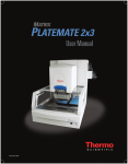
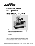
Versette System Calibration Flowchart
All calibration steps require the use of the Calibration Plate. The methods are shown below:
STEP 1
Verify communications with the
Versette System
STEP 2
Verify Versette Setup
STEP 3
Load NTC Housing
and
NTC Teach Tool
STEP 4
Calibrate
Stage XY
STEP 5
Calibrate
Z Axis
Figure 1.
Versette Calibration Master Flowchart
Required Equipment
• Versette system with 6-stage assembly
• ControlMate software, installed on computer or laptop with communications cable
• Calibration Plate
• NTC Teach Tool
28
Versette ControlMate User Manual Rev. B
Thermo Scientific
4
Calibration
STEP 1: Verify Communications with the Versette System
1. Verify that the stage assembly has been installed properly on the system.
See Installation section.
2. Connect the Versette to a computer running ControlMate software. Refer to the
ControlMate User Manual for details on setting “View” options including icon size and
text displays.
3. Select
from the Main Menu.
Firmware Version x.xx.xx
Bitmap Version x
Thermo Scientific
Versette ControlMate User Manual Rev. B
29
4
Calibration
4. Select
to set the system to remote operation.
Remote Mode
System operating in remote
control mode
5. Using the ControlMate software, click on the Tools menu and select “Options”.
30
Versette ControlMate User Manual Rev. B
Thermo Scientific
4
Calibration
6. Click the “Test” button.
Thermo Scientific
Versette ControlMate User Manual Rev. B
31
4
Calibration
7. Verify that the Device Connection is OK.
The system defaults to Serial Port 1. If necessary, use the arrow keys to select the Serial
Port (RS232 or RS232 Virtual Serial Communication port) for you computer connection
and re-test. Always check your serial cable connections if there is a communication
problem.
Note! If you are unable to connect, verify that your computer is recognizing the port that
the communication cable is attached to on your computer. You do this through Device
Manager. In Windows, select Start then Control Panel, then Hardware and Sound (on
Windows 7 systems), then Device Manager. The screen should display the port as shown
below:
8. Click on the “Test” button to verify that the Device Connection is OK.
32
Versette ControlMate User Manual Rev. B
Thermo Scientific
4
Calibration
STEP 2: Verify Versette System Setup
1. From the Add-Ins drop-down menu, select “Versette Setup”.
2. Click the “Query Versette” button to confirm machine and ControlMate are properly
communicating. Drop-down fields will automatically prefill with the appropriate
information.
You can also make any changes to the Configuration File Settings by selecting the correct
system configurations from the drop-down menus. Check marks should be placed next to
all optional equipment as shown below (even if not installed, as it will not affect
performance). A check mark should be placed next to the RFID at all times during
calibration and normal system operation. This feature is only turned off during
manufacture or field service troubleshooting activities. When finished, click “OK”.
Click to populate
fields with info
from Versette
system.
Thermo Scientific
Versette ControlMate User Manual Rev. B
33
4
Calibration
STEP 3: Install the NTC Pipetting Module and NTC Teach Tool
If not installed, install an NTC Pipetting Module as follows:
1. From the Add-Ins drop-down menu, select “Change Pipetting Module”.
2. Follow the screen prompts to install an NTC pipetting module:
a.
34
Verify that all safety shields are in place, then click “Start”.
Versette ControlMate User Manual Rev. B
Thermo Scientific
4
Calibration
b. Move the release bar DOWN then click “Next”.
Rotate Release Bar
to point down
Rotate Release Bar to DOWN position.
Thermo Scientific
Versette ControlMate User Manual Rev. B
35
4
Calibration
c.
Carefully lift and position the pipetting module onto the pipetting module holder
then click “Next”.
Carefully lift and position the pipetting module
into the system
36
Versette ControlMate User Manual Rev. B
Thermo Scientific
4
d.
Calibration
Wait for the system prompt, then move the release bar UP, then click “Next.”
Rotate Release Bar to UP position.
Thermo Scientific
Versette ControlMate User Manual Rev. B
37
4
Calibration
e. Wait for the system prompt then connect the pipetting module cable, then click
“Next”.
The cable connector may have red dots which align to the system connector. The
dots are difficult to see due to their location. Follow the screen messages carefully and
press in firmly to ensure proper connection.
f.
Wait for the system to complete the load sequence and home all axes. Various
messages will be displayed. When complete, the system will display “Change
Complete...”. Close the window by clicking the “X” in the upper right-corner.
Note! If a head is already installed, simply open and close the door as requested to
continue to work through the software/hardware interlock prompts.
38
Versette ControlMate User Manual Rev. B
Thermo Scientific
4
Calibration
3. From the Add-Ins drop-down menu, select “Change pipetting head and Tips”.
4. Place a checkmark in “Change Head” then use the scroll-down field to select “96/384
Teach Tool”.
Thermo Scientific
Versette ControlMate User Manual Rev. B
39
4
Calibration
5. If a tip magazine is in the system, remove it, then click “Next”.
6. If a pipetting head is installed, remove it, then click “Next”.
40
Versette ControlMate User Manual Rev. B
Thermo Scientific
4
Calibration
7. Insert any 96- or 384- channel pipetting head, then click the “Next”.
Press firmly in until the pipette head clicks in place.
Thermo Scientific
Versette ControlMate User Manual Rev. B
41
4
Calibration
8. Insert the 96/384 Teach Tool, then click “Next”.
Press firmly in until the 96/384 teach tool clicks in place.
42
Versette ControlMate User Manual Rev. B
Thermo Scientific
4
Calibration
STEP 4: Calibrate Stage XY Coordinates
1. Place the Calibration Plate flat in position on Stage 2 with the “96/384 PIPETTING
HEAD” side facing up.
2. From the Add-Ins drop-down menu, select “Versette Calibration”.
3. Select the 96/384 Pipetting Module then click “Calibrate Stage XY”.
Thermo Scientific
Versette ControlMate User Manual Rev. B
43
4
Calibration
4. Read and comply with any instructions. Place a check mark as noted below when all
conditions are met, then click “Continue”.
5. Select Stage 2 from the drop-down menu (system defaults to Stage 2), then click “Move
to Position”.
44
Versette ControlMate User Manual Rev. B
Thermo Scientific
4
Calibration
6. After Stage 2 has moved in position under the teach tool, use “Move Z Axis” to lower the
teach tool to approximately 1 mm above the Calibration Plate.
- Select the appropriate Step size (0.1 mm, 1 mm, 10 mm, etc.), then click the Down
arrow to move the pipetting module closer to the stage position.
CAUTION Use care when moving the pipetting module to avoid hitting the stage. Select
the smallest reasonable Step size.
Lower NTC
teach tool close
to Calibration Plate.
Thermo Scientific
Versette ControlMate User Manual Rev. B
45
4
Calibration
7. Check the alignment location. The teach tool posts should be positioned so that the posts
will line up correctly to go into the plate holes.
If necessary, use the Move Stage (X and Y) commands to enter a Step size (typically
0.1 mm) then use the arrows to move the stage left or right, forward or back to achieve
proper alignment. Take great care to ensure all four posts will line up properly into the
plate holes. It is recommended to view the alignment from as many angles as practical.
Center above
hole in
“A” location
46
Versette ControlMate User Manual Rev. B
Thermo Scientific
4
Calibration
8. Lower the pipetting module slightly to verify that the X-axis and Y-axis alignments are
properly set. Take care to check the left rear hole and the right front hole marked as “A”
locations on the Calibration Plate are in alignment.
Center above hole
LEFT REAR
lower teach tool
into hole
marked “A”
RIGHT FRONT
lower teach tool
into hole
marked “A”
Thermo Scientific
Versette ControlMate User Manual Rev. B
47
4
Calibration
9. Click “Save” to save the calibration coordinates, read the message, then click “OK”.
10. Wait approximately 15-30 seconds or more for the system to save the changes. Do NOT
close the window! Once the values are saved to the computer, the machine homes the Z
Axis. The window will close automatically and return to the Calibration Menu. Wait for
the cycle to complete and all motions to stop.
IMPORTANT If you close the window before the calibration is saved, you will need to
restart the entire calibration process. You may also need to power-cycle the Versette
system.
wait to finish saving
48
Versette ControlMate User Manual Rev. B
Thermo Scientific
4
Calibration
STEP 5: Calibrate the Z-axis
1. Select “Calibrate Z-axis”.
2. Read the instructions and verify that all items have been completed, then select the check
box to continue, then click “Continue” to begin the calibration process.
Thermo Scientific
Versette ControlMate User Manual Rev. B
49
4
Calibration
3. The Z-Axis is calibrated from Stage 2. Verify that Stage 2 is displayed in the position box,
then press “Move to Position.” The head and stages will move to position the Teach Tool
over the Calibration Plate on Stage 2.
4. Set the Step size, then use the arrows to move the teach tool down until it is just touching
the calibration plate.
5. Take a piece of paper the thickness of a standard notepad paper or a sticky note and try to
slide the paper underneath the left front calibration pin. If the pin is touching the plate
you should not be able to slide the paper underneath the pin.
6. Move the step size up by 0.1mm increments until the paper can just slide underneath the
pin.
Note! For experienced users, you can also just visually verify that the pin is just off the
calibration plate without using the piece of paper as a guide. Ensure that the left front pin
is just touching the plate and then move the step size up by one 0.1mm increment.
50
Versette ControlMate User Manual Rev. B
Thermo Scientific
4
Calibration
CAUTION If the front pins are different heights, use the longest pin.
7. Click “Save” to save the new calibration coordinates, then click “OK” on the pop-up
window.
8. Wait approximately 15 to 30 seconds for the system to save the changes. Do NOT close
the window! The window will close automatically and return to the Calibration Menu.
Once changes are made, the machine will go through a homing cycle. Wait for the cycle
to complete and all motions to stop.
Thermo Scientific
Versette ControlMate User Manual Rev. B
51
4
Calibration
IMPORTANT If you close the window before the calibration is saved, you will need to
restart the entire calibration process. You may also need to power-cycle the Versette
system.
Wait while system updates.
STEP 6: Calibrate Reagent Reservoir Fill Sensor
The following procedure should be used to calibrate the optional Reagent Reservoir Fill
Sensor.
1. Select “Versette Calibration” from the Add-Ins menu, as shown:
52
Versette ControlMate User Manual Rev. B
Thermo Scientific
4
Calibration
2. Ensure the “96/384 Pipetting Module” is already selected with a check mark, select
“Reagent Reservoir Fill” module, then click “Calibrate Reagent Reservoir Fill Sensor”.
CAUTION DO NOT uncheck and re-check 96/384 module checkbox after Versette
system has been calibrated as the machine could lose calibration parameters and might
need to be re-calibrated.
3. Read and verify all displayed requirements on the screen, then confirm by clicking on the
check box area (see below) then select “Continue”.
Thermo Scientific
Versette ControlMate User Manual Rev. B
53
4
Calibration
4. Select the Reservoir type from the pull-down menu, then follow the on-screen calibration
steps:
1. Click “Move to Position” to start the process
2. Place the reagent reservoir at Stage 1
3. Fill the reservoir with liquid to the maximum level at which you want to calibrate
4. Press and hold the yellow (SET) button on the sensor until the green light starts
to blink intermittently
5. Release the SET button, the light will continue to blink
6. Briefly press the (SET) button, the light will now remain on
7. Click the (SAVE) button on the screen to save the calibration data
SET button
54
Versette ControlMate User Manual Rev. B
Thermo Scientific
4
Calibration
STEP 7: Optimizing Additional Stage Positions
This step is performed in order to ensure all the stage positions have been properly calibrated
based off the data that was referenced from calibrating the Stage 2 position.
In principle, once the Stage 2 position has been calibrated, all remaining stage positions
(1,3,4,5,6) should also be in alignment. However, it is good practice to double-check and if
necessary, make slight adjustments to the remaining stage positions as needed. This step is
optional and can be performed at a later time if any of the stage positions need to be
streamlined to work with a specific piece of labware that is either current in the default drop
down list to choose from, or a new piece of labware that has been entered for use with a
protocol/sequence. For information on adding/modifying/deleting labware refer to Editing
the Labware Library section of this manual.
1. If not already installed, you will need to install any pipetting head and the 96/384 teach
tool into the NTC pipetting module. Refer to “STEP 3: Install the NTC Pipetting
Module and NTC Teach Tool” on page 34 for details on changing the pipette head.
2. From the Tools menu, select Options.
3. When the Options window opens, select the Stage Positions tab.
Thermo Scientific
Versette ControlMate User Manual Rev. B
55
4
Calibration
4. From the drop down menu, select one of the remaining stages to be verified/calibrated (1,
3, 4, 5, or 6). Since stage position 2 has already been calibrated, you do not need to
verify/calibrate this position.
5. Place the Calibration Plate flat in position on Stage 1 with the "96/384 PIPETTING
HEAD" side facing up.
6. Select Stage 1 from the drop-down menu then click "Move to Position".
7. After Stage 1 has moved in position under the teach tool, use "Move Z Axis" to lower the
teach tool to approximately 1 mm above the Calibration Plate. Select the appropriate Step
size (0.1 mm, 1 mm, 10 mm, etc.), then click the Down arrow to move the pipetting
module closer to the stage position.
CAUTION Use care when moving the pipetting module to avoid hitting the stage. Select
the smallest reasonable Step size.
Lower NTC teach tool close to the
Calibration Plate.
56
Versette ControlMate User Manual Rev. B
Thermo Scientific
4
Calibration
8. Lower the pipetting module slightly to verify that the X-axis and Y-axis alignments are
properly set. Take care to check the left rear hole and the right front hole marked as "A"
locations on the Calibration Plate are in alignment.
Center above hole
Left Rear
lower teach tool
into hole
marked “A”
Right Front
lower teach tool
into hole
marked “A”
Thermo Scientific
Versette ControlMate User Manual Rev. B
57
4
Calibration
9. Check the alignment location. The teach tool posts should be positioned so that the posts
will go into the plate holes.
If necessary, use the Move Stage (X and Y) commands to enter a Step size (typically
0.1 mm) then use the arrows to move the stage left or right, forward or back to achieve
alignment. Take great care to be as ensure all four posts will go into the plate holes. It is
recommended to view the alignment from as many angles as practical.
Center above
hole in
“A” location
58
Versette ControlMate User Manual Rev. B
Thermo Scientific
4
Calibration
10. If you did not make any changes to either the X or Y axis steps, then skip to step 13.
11. If you have made changes to either the X or Y axis steps, then click "Save" to save the new
calibration coordinates.
12. Wait approximately 15-30 seconds or more for the system to save the changes. Do NOT
close the window! Once the values are saved to the computer, the "Uploading Data to
Versette" message disappears. The Z axis remains lowered in the calibration plate and
does not automatically home.
Wait to finish
saving
CAUTION IMPORTANT NOTICE: If you close the window before the calibration is
saved, you need to restart the entire calibration process. You may also need to power-cycle
the Versette system.
Thermo Scientific
Versette ControlMate User Manual Rev. B
59
4
Calibration
13. Repeat steps 4 through 12 until all remaining stage positions have been
verified/calibrated.
60
Versette ControlMate User Manual Rev. B
Thermo Scientific
4
Calibration
14. After the last stage position has been completed, click on the Home All button. The
machine homes the Z Axis and homes the stage to the left of the machine. Wait for the
cycle to complete and all motions to stop.
15. Close the Options window.
Thermo Scientific
Versette ControlMate User Manual Rev. B
61
4
Calibration
Saving, Recalling, and Backing Up Calibrated Data
Calibrated data includes stage coordinate calibration data. When a Versette system is
calibrated, the calibration data is stored in the ControlMate Data Folder on the computer
where the calibration of the machine was performed and automatically saved to the Versette
system.
Calibrated Data (Download Buttons in Versette Set Up)
Using the Calibrated Data buttons saves calibration status for each axis (S,X,Y,Z), identifies
what was last used, if reagent reservoir fill was calibrated, head type info, saves position
information, etc.
When the machine is calibrated and coordinates are saved, the calibration data is stored in
both the CM Data folder (Versette.ini file) and the machine.
62
Versette ControlMate User Manual Rev. B
Thermo Scientific
4
Calibration
Save to Versette
Uploads the calibration data stored in the CM Data folder to the machine.
Example: When a new Firmware version is loaded, the calibration data stored in the CM
Data folder needs to be saved back to the Versette.
Note! Labware Library custom entries and volumetric calculations are not affected or
overwritten.
Load from Versette
Downloads the data from the machine to the CM Data folder.
Example: When a new workstation is set up, the calibration data stored on the machine needs
to be saved into the CM Data folder.
Note! Labware Library custom entries and volumetric calculations are not affected or
overwritten.
Thermo Scientific
Versette ControlMate User Manual Rev. B
63
4
Calibration
Save to File
Exports the data from the CM Data folder to a saved backup file, the user can specify the file
name.
Example: As a precaution the user wants to save a copy of the calibration data so the machine
doesn’t have to be recalibrated from scratch. The file can be loaded back into the
CM Data folder using “Load from File”.
Note! Labware Library custom entries and volumetric calculations are not affected or
overwritten.
Load from File
Imports the data from a saved backup file to the CM Data folder.
Example: If different workstations are used with a single machine, the calibration data stored
from the saved external file needs to be saved into the CM Data folder for each
workstation.
Note! Labware Library custom entries and volumetric calculations are not affected or
overwritten.
64
Versette ControlMate User Manual Rev. B
Thermo Scientific
4
Calibration
Calibrated Data / Backing Up Versette Files
This should be done periodically to ensure you have the most current information saved in
case you need to change / upgrade workstations or recover calibration data from the Versette.
1. In ControlMate, from “Add-Ins” menu item, select “Versette Setup”.
Calibration data
file handling
options
2. Select “Save To File” to save a copy of the calibration data to a file on your computer.
3. Save the file to a backup location, for example, the computer desktop, C:Drive, data
folder, flash drive, etc.
4. Rename the file by placing an identifier in the front of it, e.g. today’s date:
10-13-12VersetteINIExport.bak
Thermo Scientific
Versette ControlMate User Manual Rev. B
65
4
66
Calibration
Versette ControlMate User Manual Rev. B
Thermo Scientific
5
Labware Library
The ControlMate software comes pre-loaded with an electronic ‘library’ of pre-loaded labware
dimensions. This selection of predefined microplates and tubes allows instant use of a variety
of labware by ControlMate and the Versette system. The “Edit Labware Library” function
(detailed in the following pages) allows a user to modify, add, or delete labware entries.
Information for each piece of labware can will include dimensional shapes, widths, spacing,
overall height, liquid handling depths, and all critical dimensions required to ensure proper
operation.
Editing/Entering Labware Items
There are two approaches for editing/entering labware items:
• Use existing labware as a template to create new custom items: Modifying existing
labware is when you have a piece of labware that has almost the same dimensions as the
custom piece you are entering. Use an existing default labware selected from the drop
down menu to modify:
–
name of an existing piece of labware - without changing the dimension parameters
–
dimension parameters of an existing labware item - resaving with current name
–
the name / dimension parameters
• Enter a new item: this is when you create custom labware from scratch that is not already
pre-loaded into the library and not available from the drop down menu as a guide. Enter
the dimensions and parameters in appropriate fields:
Thermo Scientific
–
measure labware item with calipers
–
enter measurements / dimensions directly from a manufacturer's specification sheet
Versette ControlMate User Manual Rev. B
67
5
Labware Library
1. From the Add-Ins menu, select “Edit Labware Library".
The Edit Labware Library window opens with default information for the first labware item
in the Labware Library list from the drop down menu.
68
Versette ControlMate User Manual Rev. B
Thermo Scientific
5
Labware Library
Edit Labware Library Screen Details
There are nine sections that need to have the dimensions and parameters of labware items
entered.
• Vessel Selection
• Description: this is the title of the labware item selected from a drop down menu.
The description field lists the different names of the labware items to be used within a
protocol. If you click on the drop-down arrow you'll notice that there are over 50
items that are entered as default labware. They are listed in order by numeric first,
followed by alpha entries.
–
NEW: enter in a new labware item into the drop down menu when selecting a
vessel type in the Move To Position step in a sequence
–
DELETE: permanently removes a labware item from the drop down menu when
selecting a vessel type in the Move To Position step in a sequence
• Detail For
• Description: title of the labware item selected from the drop down menu is listed
• Labware Type: plate, reservoir, tip wash
• Overall Height: total height of the labware item (including the skirt of a plate, rack,
etc.)
• Available for Selection (i.e. visible in drop down lists): if check box is selected, the
labware is shown in the drop down menu for selecting a vessel type in the Move To
Position step in a sequence
• Safe Travel Offset: safe height that the tips travel above the labware selected: default
2mm
• Well Layout
• Well Shape: shape of well: round, square, not applicable
• Well Width: internal width of well, tube or vial
Thermo Scientific
Versette ControlMate User Manual Rev. B
69
5
Labware Library
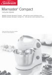
• A1 Offset
• From Left Edge: measuring into the A1 center well from the left edge of plate:
default based on 96 well plate 14.38mm
• From Top Edge: measuring into the A1 center well from the top edge of plate:
default based on 96 well plate 11.23mm
Note! In places where you can't move equal distances across a plate, reservoir, using
non conventional plates or labware with staggered wells (e.g. honeycomb, divided
reservoirs) the tips won't line up properly to do custom incremental adjustments.
14.38
mm
From Left Edge
9 mm well-to-well
11.23 mm
From Top Edge
• Well Spacing
• Col to Col: measuring the well to well center in a column-wise direction:
default based on 96 well plate 9mm on center, 384 well plate 4.5mm on center
• Row to Row: measuring the well to well center in a row-wise direction:
default based on 96 well plate 9mm on center, 384 well plate 4.5mm on center
• Well Count
• Row: total number of rows available
• Column: total number of columns available
• Allow incremental movements: if check box is selected, the labware item can be used
to perform incremental movements across a plate; useful for serial dilutions
Note! In places where you can't move equal distances across a plate, reservoir, using
non conventional plates or labware with staggered wells (e.g. honeycomb, divided
reservoirs) the tips won't line up properly to do custom incremental adjustments.
70
Versette ControlMate User Manual Rev. B
Thermo Scientific
5
Labware Library
• Liquid Handling Depths: these are the depths that the tip will go down into the labware;
i.e., plate, tube rack. These heights are not only based on what you enter, but take into
consideration the type of tip you select in your protocol. ControlMate software takes into
fact the length of tip in conjunction with the depths entered for specific labware choices.
Liquid handling depths pre-entered are guidelines for entering the heights. However,
based on the protocol and depths you need to go into the plate or tube rack, you can
adjust these accordingly.
Note! Liquid handling depths can be adjusted in the Edit Labware Library section for
your labware (recommended) or in the actual protocol in the aspirate or dispense steps. In
the aspirate or dispense steps the liquid handling depths are listed as the 'predefined'
heights from a drop down menu that are selected. Or, you could also choose a 'specific'
height that is measured from the well top. The reason why you should adjust the actual
liquid handling depths in the Labware Editor is the heights (once optimized) selected
from the predefined heights will be consistent throughout your protocols based on the
labware item selected. If you select to use the 'specific' height, you would need to ensure
all your aspirate and dispense steps have the same selected height measurement entered
throughout the protocol. Here you could accidentally forget to enter it or you would have
to remember the measurement needed.
• Well Bottom: height is measured from top of well to well bottom (tip actually
touches the bottom of the well)
• Aspirate: measurement of aspirate height (typically 2mm above well bottom)
• Dispense: measurement of dispense height (typically 2mm below well top)
• Pipette Head Usage: ability to select the pipetting heads to use with a labware item
• Check boxes for 96, 384 heads: select the appropriate heads compatible with your
labware
• Stage Location Usage: ability to select stage locations to use with a labware item
• Check boxes for all stages locations: select the appropriate stages compatible with
your labware. Some labware items, i.e., tube racks may be too tall to place on the
upper stage positions and could potentially interfere with proper head/tip movement.
It is suggested to use taller labware items on the lower stage positions (1,2) as
appropriate.
Modify Existing Labware
There are several ways to modify an existing piece of labware. Use an existing default labware
selected from the drop down menu to modify:
Override current piece of labware without having to create a New item
a. dimension parameters of an existing labware item without changing the labware
name - resaving with new dimension parameters with current name
• Requires creating a New piece of labware
Thermo Scientific
Versette ControlMate User Manual Rev. B
71
5
Labware Library
b. name of an existing piece of labware without changing the dimension parameters resaving with new name
c. both the name / dimension parameters - resaving with new dimension parameters
and new name
Changing Dimension Parameters and Resaving with Same Name
1. To modify an existing piece of labware or simply override the dimensions of a current
labware item and resave using the same name (example a), select a similar labware item
from the existing drop down list in the description in Vessel Selection.
2. Edit the dimension parameters for the appropriate fields.
72
Versette ControlMate User Manual Rev. B
Thermo Scientific
5
Labware Library
3. Click Save.
4. Once the plate type is resaved, the new dimensions are applied to this labware item. The
labware item appears in the drop-down menu on the description field in the Edit labware
Library (for future editing) and within the Move To Position to select your new vessel
type from the Labware Library.
Thermo Scientific
Versette ControlMate User Manual Rev. B
73
5
Labware Library
Name Change Only
If Changing the Name and Dimension Parameters, follow this same Guideline (example c).
To modify an existing piece of labware and rename it (example b), select a similar labware
item from the existing drop down list in Vessel Selection.
1. The first step is to click on the New button.
74
Versette ControlMate User Manual Rev. B
Thermo Scientific
5
Labware Library
2. An Edit Labware Library screen appears to enter in a new vessel type. All the fields are
cleared as ControlMate is waiting for your next step. A section named New Vessel Type
appears with a Similar to…drop down menu.
Thermo Scientific
Versette ControlMate User Manual Rev. B
75
5
Labware Library
3. Select an existing vessel type that is similar to the plate type of vessel type that you want to
enter. Click on the drop-down arrow in the Similar to… field and select the item which
best corresponds to the custom item you want to enter. For this example, select the 96
MicroWell Plates Flat Bottom PS.
4. Click the Load button. This will load all the existing information for the similar plate you
have chosen and you can simply edit over the details which don't match.
5. In the Detail For section, type in the name of the plate that you want to use in the
Description field. Be sure to make it something you would recognize, for example; plate
type, name brand of the product, catalog number of the product, or something specific
related to your protocol that is easily identifiable.
For this example, rename the description to a 96 well flat from ABC Company with part
number 1234 or "96 Well Flat - ABC #1234". Once you've established a name you can
now go through the remaining fields and change the corresponding information as
appropriate. In this case, because it is a similar 96 well plate to one that was currently in
the labware library, you may not need to change any fields.
76
Versette ControlMate User Manual Rev. B
Thermo Scientific
5
Labware Library
Remember that if you want this plate type to be available on the drop-down list to select for
protocols, ensure that the checkbox next to Available for selection in the Detail For section is
checked.
Thermo Scientific
Versette ControlMate User Manual Rev. B
77
5
Labware Library
6. Typically you would edit the remaining specification for the appropriate fields. However,
in this example you are just changing the name of the labware item so no additional
changes are necessary. However, if you needed to change and dimension or parameters
now would be the time. Once you have renamed the plate, click Save.
78
Versette ControlMate User Manual Rev. B
Thermo Scientific
5
Labware Library
7. Once the plate type is saved, your new item will now appear in the drop-down menu on
the description field in the Edit labware Library (for future editing) and within the Move
To Position to select your new vessel type from the Labware Library.
Note! If you currently had a sequence open with the Move To Position step accessible,
the labware item that was just saved in the Labware Editor may not appear in the drop
down list. Refresh the list by closing the Move to Position step and reopening it.
Thermo Scientific
Versette ControlMate User Manual Rev. B
79
5
Labware Library
Entering New/Custom Labware
To enter a new/custom piece of labware, you can either select a similar labware item from the
existing drop down list and overwrite the information or start with a clean set of empty fields
to enter in new dimension parameters. For this example, enter in a new set of dimension
parameters.
1. Click on the New button.
80
Versette ControlMate User Manual Rev. B
Thermo Scientific
5
Labware Library
2. An Edit Labware Library screen appears to enter in a new vessel type. All the fields are
cleared as ControlMate is waiting for your next step.
3. Since you are entering a custom piece of labware from scratch, theoretically there is no
template or similar piece of labware to prefill in the fields. Skip selecting the Similar To…
as you have nothing to pre-load. None of the fields will pre-fill as you have not selected
something similar to what you're using. So in this case, you would have to enter in all the
fields as appropriate.
Thermo Scientific
Versette ControlMate User Manual Rev. B
81
5
Labware Library
4. In the Detail For section, type in the name of the plate that you want to use in the
Description field. Be sure to make it something you would recognize, for example; plate
type, name brand of the product, catalog number of the product, or something specific
related to your protocol that is easily identifiable. For this example, type the description as
2.0mL Tubes from ABC Company with part number 1234 or "2.0mL Tubes - ABC
#1234".
82
Versette ControlMate User Manual Rev. B
Thermo Scientific
5
Labware Library
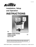
5. If you have a manufacturers spec sheet entering the information will be very simple as you
would be taking the dimensions directly from the document and entering them into the
appropriate fields. However, without the manufacturers spec sheet you will need a set of
calipers to begin taking the necessary measurements to fill in all appropriate fields. See
examples of these tools below:
Manufacturer's Specification Sheet
Thermo Scientific
Digital Calipers
Versette ControlMate User Manual Rev. B
83
5
Labware Library
6. Under the Labware Type there are three valid elections to choose from within the
drop-down menu: plate, reservoir, and tip wash. In this case the tubes in the rack are
considered a plate.
84
Versette ControlMate User Manual Rev. B
Thermo Scientific
5
Labware Library
7. The Overall Height field is the total height of the custom labware item that will be set up
on the stage; for example if you are just using a plate, the height would be measured from
the bottom of the skirt to the well top. However, if you are using tubes / vials within a
rack, you need to install a tube / vial in the rack first. The height is measured from the
bottom of the rack to the top of the tube / vial.
Plate
Thermo Scientific
Tubes Installed in Rack
Versette ControlMate User Manual Rev. B
85
5
Labware Library
8. Remember that if you want this plate type to be available on the drop-down list to select
for protocols, ensure that the checkbox next to “Available for selection...” in the Detail For
section is checked.
86
Versette ControlMate User Manual Rev. B
Thermo Scientific
5
Labware Library
9. For the Safe Travel Offset field, leave the default of 2mm.
Thermo Scientific
Versette ControlMate User Manual Rev. B
87
5
Labware Library
10. In the Well Layout section, enter the Well Shape of your item. From the drop-down
menu you have three choices: round, square and not applicable. In this case the well
layout is round.
88
Versette ControlMate User Manual Rev. B
Thermo Scientific
5
Labware Library
11. Well Width can be measured from a plate well or in the case of using a rack with tubes /
vials, you would measure the actual width of the tubes / vials as shown below.
Thermo Scientific
Versette ControlMate User Manual Rev. B
89
5
Labware Library
12. For the A1 Offset, measure the center of the A1 position of the well or tube/vial:
a. From Left Edge: measurement of a plate from the left side of the plate into the center
of the A1 well.
b. From Top Edge: measuring into the A1 center well from the top edge of plate:
default based on 96 well plate 11.23mm
14.38
mm
From Left Edge
9 mm well-to-well
11.23 mm
From Top Edge
Note! In places where you can't move equal distances across a plate, reservoir, using
non conventional plates or labware with staggered wells (e.g. honeycomb, divided
reservoirs) the tips won't line up properly to do custom incremental adjustments.
90
Versette ControlMate User Manual Rev. B
Thermo Scientific
5
Labware Library
If you do this correctly, your tips will be perfectly centered in 96 and 384 formatted well
plates, as well as, in the tubes/vials within a rack.
Note! On some labware, the bottom of the labware item might have the centered
holes or indications imprinted so you can easily measure these dimensions. However,
a manufacture's spec sheet would be ideal to gain the information for these two
measurements.
Use the bottom of a labware item whenever possible, otherwise when setting up your
labware in the editor you will have to make the necessary tweaking to get it perfectly
aligned in the well centers, which is just time consuming but can be done just as
accurately.
Thermo Scientific
Versette ControlMate User Manual Rev. B
91
5
Labware Library
13. For Well Spacing, measure from column to column; this is from the center of the first
column to the center of the column next to it. Now measure from row to row; this is from
the center of the first row to the center of the next row.
92
Versette ControlMate User Manual Rev. B
Thermo Scientific
5
Labware Library
14. For the Well Count, enter the number of rows and columns across the plate.
Thermo Scientific
Versette ControlMate User Manual Rev. B
93
5
Labware Library
15. Select the check box if you want to “Allow Incremental Movements” across the labware
item. This is beneficial when you want to do multi-dispensing or a serial dilution across a
plate/rack.
Note! There are some cases where you might not want to do incremental movements, so
choose accordingly. For example, in places where you can't move equal distances across a
plate, reservoir, using non conventional plates or labware with staggered wells (e.g.
honeycomb, divided reservoirs) the tips won't line up properly to do custom incremental
adjustments.
94
Versette ControlMate User Manual Rev. B
Thermo Scientific
5
Labware Library
16. For the Liquid Handling Depths, there are three entries which need to be entered; well
bottom height, aspirate height, and dispense height. Guidelines for entering
measurements are as follows
Table 2.
Well Bottom
Aspirate
Dispense
Tip touches well bottom
Tip is 0.5 mm off well
bottom
Tip is 2.0 mm off below well
top
Optimize the liquid handling depths (heights) for a sequence by adjusting this value to a more
specific measurement to meet the needs of your application based on sample viscosity and the
volume of the sample contained in the well. Raise or lower the tip the appropriate height
within the well. Remember; when creating your measured values, the higher the number, the
tip is positioned lower into the plate. The lower the number the tip is positioned higher in the
plate.
• Well Bottom - is typically the measurement of the actual bottom of the well. In most
applications it may not be desirable to aspirate or dispense sample from the well bottom.
This is because the tip cannot effectively create a vacuum to aspirate or dispense liquid if
the tip is directly touching the well bottom. If you try to aspirate from the well bottom,
no liquid would appear to go up into the tip until the tip starts to move out of the well,
and then liquid could jump up quickly in the tip causing an air column in the tip or
bubbles in the liquid. If you try to dispense from the well bottom, no liquid would appear
to be dispensed into the well until the tip starts to move out of the well, and then it could
create frothing, splashing or bubbles. In both cases, an accurate sample may not be
aspirated or dispensed. So you would need to determine if you want to actually be
touching the well bottom or making an adjustment to have it very close, but not
touching.
Thermo Scientific
Versette ControlMate User Manual Rev. B
95
5
Labware Library
To measure the well bottom, make sure you have a set of calipers that can measure the depth.
Insert the depth measuring end as shown and ensure this end touches the exact bottom of the
well. Record your measurement in the Well Bottom field.
96
Versette ControlMate User Manual Rev. B
Thermo Scientific
5
Labware Library
• Aspirate - aspirate height is typically entered as an 2 mm above the well bottom. This is to
ensure that you are far enough into the well to aspirate liquid, but not touching the well
bottom.
Thermo Scientific
Versette ControlMate User Manual Rev. B
97
5
Labware Library
• Dispense - dispense height is typically entered 2 mm below the well top but may be
adjusted to prevent splashing, etc., depending on the dispense volume and fluid
properties This is to ensure that you are deep enough into the well to dispense liquid, but
slightly higher from the aspirate height.
17. Under the Pipette Head Usage section you will need to verify and select which pipetting
heads can be used with your labware. Simply check the appropriate boxes by selecting and
deselecting the check boxes accordingly.
98
Versette ControlMate User Manual Rev. B
Thermo Scientific
5
Labware Library
18. Under the Stage Location Usage section you need to identify which stages the labware
item is compatible. With taller labware items these might be restricted to the lower stages
in locations 1 and 2. For standard height or shorter labware items, you could use any of
the stage locations 1 - 6.
Thermo Scientific
Versette ControlMate User Manual Rev. B
99
5
Labware Library
19. Next you need to save the plate type. Once the plate type is saved, the item description
field will pre-fill with the labware description that was just created.
20. Your new item now appears in the drop-down menu on the description field in the Edit
labware Library (for future editing) and within the Move To Position to select your new
vessel type from the Labware Library.
100
Versette ControlMate User Manual Rev. B
Thermo Scientific
5
Labware Library
Note! If you currently had a sequence open with the Move To Position step accessible,
the labware item that was just saved in the Labware Editor may not appear in the drop
down list. Refresh the list by closing the Move to Position step and reopening it.
Thermo Scientific
Versette ControlMate User Manual Rev. B
101
5
Labware Library
General Guidelines
Remember when adding items in the labware library; make sure your new entry is available
for viewing from the drop down list to select for your protocols. The only time you would
choose to uncheck this box is if you would like to only show your custom labware additions or
selected labware items commonly used to the drop down list. This comes in handy when
writing protocols and you only want to choose from a select number of labware items. Instead
of having the original default 50+ items listed, you can choose to only have the items you
select to limit the amount of time scrolling through the list.
102
Versette ControlMate User Manual Rev. B
Thermo Scientific
5
Labware Library
However you do have an alternate option to limit the amount of items in the drop-down
menu in the labware library. When you are in the edit labware library window, any existing
pre-loaded labware can be selected from the drop-down menu. Once an item is selected, next
to the description field you'll see a delete button. From here you can remove any labware from
the pre-loaded default list by clicking on the delete button.
CAUTION Use extreme caution in selecting and deleting labware items from the default drop
down menu in the Edit Labware Library section. Once the item is deleted it cannot be
recovered. This is why the “available for selection” checkbox was placed into the edit labware
library as simply selecting and deselecting this box for certain labware items can customize
your drop down list for your needs. By using this checkbox option, you can bring labware
items back into view at any time as needed.
Thermo Scientific
Versette ControlMate User Manual Rev. B
103
5
Labware Library
104
Versette ControlMate User Manual Rev. B
Thermo Scientific
6
Creating Pipetting Programs
A pipetting program is a sequence of pipetting actions that accomplishes a pipetting task. In
the ControlMate software, the pipetting program is called a sequence file. Separate sequence
files can be created for a number of different processes, including serial dilutions,
plate-to-plate transfers, and simple dispensing operations. Once created and saved, the
sequence files can be quickly retrieved for use. The following pages describe each command
and provides example sequences to work through to better understand the creation and use of
sequences. Consult with Thermo Fischer Scientific for assistance with your specific
requirements.
IMPORTANT Due to stage/head configuration limitations, serial dilutions can be performed
as follows:
Column-wise: Stage 3 or Stage 4
Row-wise: Stage 3 or Stage 5
Six stage positions
3
1
5
4
2
6
Stage Positions
Protective covers removed to show stage layout
Actual stage design may vary from that shown
Thermo Scientific
Versette ControlMate User Manual Rev. B
105
6
Creating Pipetting Programs
Creating Sequences
The main function of the ControlMate software is to create sequences of commands, often
called ‘programs’ or protocols to aspirate and dispense fluid. (Refer to the “Sample Pipetting
Sequences” section of this manual for examples of various complete sequences and
‘tutorial-steps’ explaining how to create the sample sequences.) The software also contains a
variety of tools and ‘Add-ins’ which are used to perform basic functions such as calibrating the
motion coordinates in a Versette system.
A sequence typically consists of moving to a fluid source location on a stage, aspirating the
fluid, then moving to another location to dispense some or all of the fluid. Most sequences
can appear quite complex due to the many options for labware, aspiration, dispense, pipette
types, delays, and other system variables. ControlMate provides a visual method to create
sequences and provides a validation routine that automatically checks sequences for any
setup/programming errors.
Getting Started
Pipetting programs are created in ControlMate by selecting “File” “Create New Sequence” (or
pressing the key combination CTRL+ N, or clicking the “New Sequence” icon). You can view
and select the list of program commands (also referred to as steps) by clicking the “Add
Command” drop-down menu, or selecting commands from the Toolbox icons. Each time you
click an icon, that icon’s command is added to the sequence tree. Each command typically has
a variety of options that must be set for proper operation. For example, select a stage or a
vessel type, or the starting position or volume or speedthen clicking icons in the Toolbox to
add commands to the sequence. Each icon is detailed in the following pages.
.
106
Versette ControlMate User Manual Rev. B
Thermo Scientific
6
Command Toolbox
Main menu
Sequence File Editor
“Command Tree”
Creating Pipetting Programs
Command details/Editor
Command Icon Options
By default, command icons are displayed on the left side of the screen, as shown:
Thermo Scientific
Versette ControlMate User Manual Rev. B
107
6
Creating Pipetting Programs
Select “View”, “Toolbox icon size” then “Large” to increase the size of the icons.
If desired, select “View”, “Toolbox Text” to display text labels beneath each icon.
108
Versette ControlMate User Manual Rev. B
Thermo Scientific
6
Creating Pipetting Programs
Commands: Summary
Commands are summarized in the following table. Refer to the Versette User Manual for
details on system operation. Refer to the following pages for specific details on each
command.
Table 3.
Icon
Thermo Scientific
Commands
Command Name
Purpose/Usage
Home axes
Resets all stage and head motors to their home positions. This
is typically performed upon system startup or following the
installation of a pipetting head. If desired, you can use this
command to Home all axes to ensure all motions are highly
accurate.
Speed Control
Adjusts speed (aspiration or dispensing speed), horizontal and
vertical stage speeds, etc.
Move
Move a stage or pipetting head, or both. For example, a stage
must be moved under the pipetting tips prior to the Aspirate
or Dispense command.
Collect pipette
tip(s)
This command will pause the system and wait for the user to
load tips. See the Eject pipette tips command below. Also, refer
to the Versette User Manual for instructions to load or unload
pipette tips.
Eject pipette
tip(s)
This command will pause the system to prompt the user to
remove the pipette tips, as may be required to change tips at
the end of processing. Depending on system software versions,
a message may be displayed to prompt the user, or an external
call can be made to a program such as Windows Paint to
display a user-selected graphic to display. Refer to the Versette
User Manual for instructions to load and unload pipettes.
Aspirate
Aspirates a measured volume. Typically preceded by a move
command.
Dispense
Dispenses a specific volume or all of the liquid in the tips, with
or without blowout. Typically be preceded by a move
command.
Delay
Inserts a pause into a program to stop processing according to
the pause parameters. Once the continue condition has been
reached, the program continues to the next step within the
sequence.
Versette ControlMate User Manual Rev. B
109
6
Creating Pipetting Programs
Table 3.
Icon
Commands
Command Name
Purpose/Usage
Mix
Aspirates and dispenses a measured volume in specified cycles
to mix content of the well in a microplate. Should be preceded
by a move command.
Pump
Controls pump speed and settings.
Wash Tips
Washes inside and outside of pipette tips. Requires tip wash
station and/or automated wash reservoir.
Stage Map
Allows the user to set the default heights for all stage positions
by specifying the labware layout at the start of the run. (Move
commands specifying labware other than those in the stage
map will cause the labware in the stage map to be overwritten.)
The Stage Map command is typically used for serial dilution
protocols. This is so the machine knows which type of labware
is present on a specific stage position on the deck so the
pipetting head will not crash into a stage position that might
have a taller piece of labware present.
Call Procedure
Calls a procedure either from within the current sequence file
or from another sequence file. Saves time by reusing an
existing procedure that has been previously saved.
Notepad
Creates a note in the sequence file. Useful for documenting the
steps in the sequence and for reminders during the pipetting
procedure.
Group
Commands
Groups together commands for a common purpose. For
example, the commands used to perform a common mix
procedure can be grouped together. See the sample programs
for examples on the use of groups.
Execute External Launches an external application. For example, launch the
Application
Windows Paint program to display a graphic on the screen to
alert the user when a step is completed, or prompt the user to
take an action. You could also launch a sound file using this
command.
110
Versette ControlMate User Manual Rev. B
Thermo Scientific
6
Table 3.
Icon
Creating Pipetting Programs
Commands
Command Name
Purpose/Usage
Procedure
A procedure is a series of commands that are ‘grouped’ and
included in a program listing. The main program can make a
special call to a sub-procedure to execute the sub procedure
commands. The procedure could be a standard pipetting
sequence that is routinely re-used in a program. Instead of
copying and pasting multiple copies of the various steps, a call
to run the ‘procedure’, can be done multiple times. For
example, a main program might call a procedure that contains
a move/aspirate/move/dispense steps, multiple times
throughout the program. Examples are provided in the
following pages for use of the Procedure command.
Execute External Execute a sequence that has been stored. A sequence could be a
Procedure
complete serial dilute program, for example, or a wash
sequence, or any sequence of commands that can be re-used
and called by another program.
Global Value
Assign Global
Value
Global Values allow simple input and re-use throughout a
sequence of a numeric, text, or other value, in multiple
locations. Use of globals values is a two-step process:
1. Define a Global Value
2. Assign a Global Value (set a value for the Global Value)
For example, if a global value of 20 μl is set for dispense
volume, and this global value is referenced a number of times
throughout the protocol, each time the dispense volume is
run, the value of 20 μl will be used. This can allow a quick
change of a complex protocol: by changing the global value
assignment to say, 30 μl, all subsequent runs of the protocol
will use the new value. Global values save time by eliminating
the need to edit a value or other entry in multiple locations in
a protocol. Examples are provided in the following pages and
in the pipetting samples section of this manual.
Thermo Scientific
Export Global
Value
This command is used to extract information held in global
values into external text based files. The usage of the command
is not just to build files used for importing into external
databases but could also be used for example to generate
reports, for example by creating HTML based files and then
viewing this in a web browser.
Script File
Execution
This advanced command allows the ‘calling’ and execution of
external scripting language files, for example, VBScript,
JavaScript, etc.
Versette ControlMate User Manual Rev. B
111
6
Creating Pipetting Programs
Main Sequence
The Main Sequence command is used to indicate which items are installed on the machine.
With these items selected you can begin to write and validate protocols based on the items
installed. This way if you select an item in the step that is not compatible with a certain piece
of labware, DARTs tip, etc., you will get a validation error to ensure your protocol is written
correctly.
• Versette:
Select the stage installed on the machine; default is the Versette 6 Position Stage “Versette
6 stage”
• Pipetting Module:
Select the pipetting module installed on the machine; default is the “96/384 Pipetting
Module”
• Pre-Installed Pipette Head:
Select the check box if a pipetting head is currently installed
• Head Type:
Select which pipetting head is installed:
–
384 channel 100μL
–
96 channel 30μL
–
96 channel 300μL
• Reset to aspirate origin:
Selecting this checkbox resets the pipetting head pistons to the zero position. This is
to ensure that the pistons have the complete travel length in order to accurately
aspirate and dispense sample. For example; if a sequence was run and interrupted or
stopped, the pistons could be left in a state where they are not at the “home” position.
The next time a sequence is run, they would start from the last position before the
sequence was aborted, not giving a full piston stroke to adequately aspirate full
volume of the pipetting head. In this case an error could occur.
If this checkbox is not selected, and there is sample in the tips from a previous
sequence, then the next sequence that is run will start without homing the syringe
axis.
112
Versette ControlMate User Manual Rev. B
Thermo Scientific
6
Creating Pipetting Programs
• Pre-Installed Pipette Tip:
Select the check box if a tip magazine is currently installed
• Tip Type:
Select which tip magazine is installed. Only the corresponding tip combinations
appear in the drop down menu to prevent the user from selecting a non-compatible
tip magazine configuration with a specified head type.
–
–
Thermo Scientific
384x100uL
–
16 x 30 uL D.A.R.T.s® (5316/5317/5318)
–
16 x 30 uL Ext. Length D.A.R.T.s (5416/5417/5418)
–
16 x 100 uL D.A.R.T.s (5326/5327/5328)
–
24 x 30 uL D.A.R.T.s (5316/5317/5318)
–
24 x 30 uL Ext. Length D.A.R.T.s (5416/5417/5418)
–
24 x 100 uL D.A.R.T.s (5326/5327/5328)
–
384 x 30 uL D.A.R.T.s (5316/5317/5318)
–
384 x 30 uL Ext. Length D.A.R.T.s (5416/5417/5418)
–
384 x 100 uL D.A.R.T.s (5326/5327/5328)
96x30uL / 96x300uL
–
8 x 30 uL D.A.R.T.s (5586/5587/5588)
–
8 x 30 uL Ext. Length D.A.R.T.s (5506/5507/5508)
–
8 x 300 uL D.A.R.T.s (5516/5517/5518)
–
8 x 300 uL Ext. Length D.A.R.T.s (5536/5537/5538)
–
8 x 300 uL Ext. Length Wide Bore D.A.R.T.s (5546/5547/5548)
–
12 x 30 uL D.A.R.T.s (5586/5587/5588)
–
12 x 30 uL Ext. Length D.A.R.T.s (5506/5507/5508)
–
12 x 300 uL D.A.R.T.s (5516/5517/5518)
–
12 x 300 uL Ext. Length D.A.R.T.s (5536/5537/5538)
–
12 x 300 uL Ext. Length Wide Bore D.A.R.T.s (5546/5547/5548)
–
96 x 30 uL D.A.R.T.s (5586/5587/5588)
–
96 x 30 uL Ext. Length D.A.R.T.s (5506/5507/5508)
–
96 x 300 uL D.A.R.T.s (5516/5517/5518)
–
96 x 300 uL Ext. Length D.A.R.T.s (5536/5537/5538)
–
96 x 300 uL Ext. Length Wide Bore D.A.R.T.s (5546/5547/5548)
–
MSIA 96 tips - type 1 (standard magazine)
Versette ControlMate User Manual Rev. B
113
6
Creating Pipetting Programs
–
MSIA 8 tips - type 1 (standard magazine)
–
MSIA 12 tips - type 1 (standard magazine)
–
MSIA 96 tips - type 2 (custom magazine)
–
MSIA 8 tips - type 2 (custom magazine)
–
MSIA 12 tips - type 2 (custom magazine)
Stage Map
Stage Map: This command is used for serial dilution protocols. This is so the machine knows
which type of labware is present on a specific stage position on the deck so the pipetting head
won’t crash into another stage position that might have a taller piece of labware present. The
plate map is a tool so you can configure the set up of the instrument when you start a
protocol. It will use your set up to determine a safe travel height and to check when doing
incremental row or column movements that the adjacent plate(s) are not taller than the one
used for the dilution (possible crash).
114
Versette ControlMate User Manual Rev. B
Thermo Scientific
6
Creating Pipetting Programs
For example; if you start out with one labware type (384 square well flat) and then have a
move command with something different (384 well deep) it will update the stage map for
future moves.
Note! As of 6-21-12, Stage Positions in the protocols override the stage map. If a different
plate is selected within the protocol, then the plate in the protocol step will override the Stage
Map selections.
Use the drop down menu in the Stage Position field to select the corresponding labware for
the protocol. You can either choose from a list of defaults or add your own and select from
your custom labware as needed. (To add/delete/modify labware, refer to the section Edit
Labware Library)
• Upper Deck this reflects the higher stage positions on the deck of the machine.
• Stage Position 3 select the labware type for stage location 3 on the deck
• Stage Position 4 select the labware type for stage location 4 on the deck
• Stage Position 5 select the labware type for stage location 5 on the deck
• Stage Position 6 select the labware type for stage location 6 on the deck
• Lower Deck this reflects the lower stage positions on the deck of the machine.
• Stage Position 1 select the labware type for stage location 1 on the deck
• Stage Position 2 select the labware type for stage location 2 on the deck
Home Axes
Home Axes: This command is used to reset or ‘home’ the stage to its default position as
occasionally it may be necessary to reset an axis to its home position during file execution. It is
possible to reset each individual axes or by selecting one option which resets all axes at once.
You can select ‘All’ or uncheck the All check box to select one or more combinations of the
X,Y,Z and Syringe Axis’.
Note! Resets all stage and head motors to their home positions. This is typically performed
upon system startup or following the installation of a pipetting head. If desired, you can use
this command to Home all axes to ensure all motions are highly accurate.
• All: this homes all the Axis’ listed in this step selection to its default location: X, Y, Z, and
Syringe.
• X Axis: this only homes the X Axis to its default location (to left)
• Y Axis: this only homes the Y Axis to its default location (to back)
• Z Axis: this only homes the Z Axis to its default location (up)
• Syringe: this only homes the Syringes to its default location (down)
Thermo Scientific
Versette ControlMate User Manual Rev. B
115
6
Creating Pipetting Programs
Move to Position
Move: This command is used when you need to move the stage to a certain stage position on
the machine. There are other fields that need to be selected to indicate what is on that
particular stage position and which head is installed. The sequence of commands is always a
‘move to’ and then ‘do something / perform an action’.
• Stage Position this reflects the position the machine will move to.
From the drop down menu select from the following choices:
• Access Stage 1 or 2: moves the stage to the default location in order to access stage 1
and 2 locations easily. The stage moves to the front center of the machine and the
slider remains open. This capability is for removing / placing items on these two
locations during a protocol.
• Access Stage 3 4 5 or 6: moves the stage to the default location in order to access
stages 3,4,5 and 6 locations easily. The stage moves to the front center of the machine
and the slider remains closed. This capability is for removing / placing items on these
four locations during a protocol.
• Reservoir Fill: moves stage 1 to the to the reservoir fill location
• Stage 1: Stage 1 is positioned underneath the pipetting head
• Stage 2: Stage 2 is positioned underneath the pipetting head
• Stage 3: Stage 3 is positioned underneath the pipetting head
116
Versette ControlMate User Manual Rev. B
Thermo Scientific
6
Creating Pipetting Programs
• Stage 4: Stage 4 is positioned underneath the pipetting head
• Stage 5: Stage 5 is positioned underneath the pipetting head
• Stage 6: Stage 6 is positioned underneath the pipetting head
• Wash: move to tip wash station location on stage 2
• Vessel Type: select labware items from a drop down list that references the Labware
Library. Choices are 96 or 384 well plates and various tube/rack configurations. (To
add/delete/modify labware, refer to the section Edit Labware Library)
• Pipette Module: defaults to the pipetting module installed on the unit
• Head: pipetting head/tip configuration installed on the unit. This can be changed
depending if you need to use 8, 12 or 96 channels. If working with serial dilution
magazines, this drop down would be changed according to the usage of columns (8) or
rows (12) incrementing across a plate
• Well Selection: ability to select the wells that will be accessed in a sequence. Depending
on the head that is selected, you can move certain directions to access the wells within a
plate.
• Incremental: select the direction to move within a plate. This feature is related to
serial dilution and plate reformatting. This movement is based on the combination of
the Vessel Type and Head selection above. For example, selecting a Vessel Type - 96
well plate and the Head type as:
–
8 channels - Start left move right, Start right move left
–
12 channels - Start top move down, Start bottom move up
–
96 channels - Start top left
Note! Selecting the 384 vessels and head type configurations will provide
additional incremental movements across the plate. Refer to the drop down
menu in this section for corresponding selections.
• Row: A - H (96 wells) / A - P (384 wells)
• Step: number of wells moved per step across the plate. For example selecting "1"
moves every row; selecting "2" moves every other row; selecting "3" moves every third
row and so on.
• Column: 1 - 12 (96 wells) / 1 - 24 (384 wells)
• Step number of wells moved per step across the plate. For example selecting "1"
moves every column; selecting "2" moves every other column; selecting "3" moves
every third column and so on.
• Empty Field represents the corresponding well locations the A1 tip will access selected
within move command. The example below represents using 12 tips in a row loaded in a
serial dilution magazine, moving from the top of the plate down to the bottom of the
plate, placing the tips in every other row. These are the rows that will be affected by this
sequence.
Thermo Scientific
Versette ControlMate User Manual Rev. B
117
6
Creating Pipetting Programs
118
Versette ControlMate User Manual Rev. B
Thermo Scientific
6
Creating Pipetting Programs
Aspirate
Aspirate: This command is used when you need to set the pick up or aspiration volume.
Aspirates a measured volume with/without air gaps and/or overstroke in tips/syringes. There
are other fields that need to be completed to indicate what features and parameters are needed
to complete this step in the sequence.
• Liquid Type: The unit is factory calibrated with multiple fluid types, at specific
temperatures and one volume point. This selection should reflect the liquid type that
matches the sample volume being delivered. There are five presets to choose from that
provides the closest match.
Thermo Scientific
–
Distilled water @ 20 - 22.5 Celsius
–
1% BSA @ 20 Celsius at 15 μL
–
70% Ethanol @ 20 Celsius 150 μL
–
30% Glycerol @ 20 Celsius at 30 μL
–
90% DMSO @ 20 Celsius at 5 μL
Versette ControlMate User Manual Rev. B
119
6
Creating Pipetting Programs
You can also modify or add new calibration values to improve pipetting accuracy of
liquids as it is possible to set a volumetric factor to use within the Aspirate and Dispense
commands. The factor can be used to cause the piston motor to increase or decrease the
number of steps required in order to achieve an accurate volume movement based on
liquid sample type and also by environment operating temperature. This will assist in
achieving very accurate volume dispensing. The factors are generated by using a standard
volumetric correction factor for the specific liquid type at the temperature range required
and to use this applied to the gravimetric measurement taken for the required volume.
The net result will be the factor that will be used to correct the piston motor to achieve
the required accuracy for the specific liquid/temperature range. (If you need to add a
specific / custom liquid type, refer to the “Volumetric Calibration” section of this
manual.)
• Pre-Air Gap: introduces an air gap at the top of the tip (before liquid is aspirated in the
tip) to ensure that there is enough force to completely dispense all liquid from a tip
during a dispense. This feature also aids in a more accurate dispense for single transfers of
small volumes. During aspiration, you have the ability to aspirate more than one sample
within a tip separated by air gaps.
• Aspirate Height: places the tip at a certain height within the well. This allows you to
position the tip in a better position to provide a more precise aspiration within the well.
For example, when aspirating sample from a well the tip may need to be better positioned
lower in the well to ensure it doesn't introduce any air into the tip.
Note! These heights are predetermined based on the vessel types selected in the MOVE
command and tips loaded in the machine.
• Predefined: there are four preset heights to choose from:
–
Well top - at the top of the well
–
Well bottom - touching the bottom of the well
–
Aspirate - 2 mm above the well bottom (default)
–
Dispense - 2 mm below the well top (default)
–
These liquid handling depths can be modified by labware type as needed to
optimize the tip heights within the well. Refer to the section Edit Labware
Library.
• Specific: select a custom height within the well
120
–
Above / below - position of tips above or below well top
–
By - the height in mm the tip is placed in the well
Versette ControlMate User Manual Rev. B
Thermo Scientific
6
Creating Pipetting Programs
• Tip Offset: places the tip in a certain XY position within the well. This can be used if the
tip needs to be in a better position to provide a more accurate aspiration within the well.
Typical aspiration takes place at the center of a well. Selecting a tip/well offset sets the tip
position either to a corner of the well, or to a specific X and Y axis offset value. For
example, it may be necessary to position the tips away from the center of each well; when
using 384-well plates with low volumes, the greatest accuracy might be provided by
positioning the tips to touch off in one of the well corners. Checking this field will allow
the setting of tip positioning either by choosing one of the pre-set positions or by entering
specific X- and Y-axis offset values.
• Predefined: there are eight preset tip offsets to choose from:
–
Back Left Corner
–
Back
–
Back Right Corner
–
Right Side
–
Front Right Corner
–
Front
–
Front Left Corner
–
Left Side
• Specific: select a custom X and Y offset within the well:
–
Left / right - X axis within the well
–
Forward / backward - Y axis within the well
–
By - the distance in mm the tip is offset in the well
• Aspirate with overstroke: can be used if this is the first aspirate prior to multiple dispenses.
The overstroke sequence aspirates an additional amount of sample, then returns a portion
of this liquid to the source. This will ensure that the piston motor is primed and improves
volumetric accuracy throughout all subsequent dispense aliquots.
• μL: when the aspirate with overstroke box is checked, enter the volume in μL to be
initially aspirated in the tip
• Return volume: amount that is returned into the source vessel
The remainder of sample in the tip is the "aspirate with overstroke volume in μL" minus
the "return volume".
For example; (overstroke volume of 5μL) - (return volume of 2μL) = 3μL sample in tip.
• Aspirate volume: amount of volume to be aspirated in μL
• Dwell time: adds a specific time to wait/pause following an aspiration to allow for the
fluid pressure to equalize within the tip or wait/pause after aspirating to allow for a
complete pick up of sample. This is an optimization feature that ensures an accurate
aspiration. Dwell time is represented in seconds.
Thermo Scientific
Versette ControlMate User Manual Rev. B
121
6
Creating Pipetting Programs
• Tip touch: set a specific positioning in the vessel for tips/syringes to touch off. This is the
"touch off" on the side wall, corner or bottom of a vessel that removes droplets adhering
to the side / bottom of the tips/syringes after an aspirate or dispense. This command
allows droplets to remain in the well rather than be carried away with the tips/syringes.
–
Left
–
Right
–
Back
–
Front
–
Back Left Corner
–
Back Right Corner
–
Front Left Corner
–
Front Right Corner
– Well Bottom (dry)
• Post-Air Gap: introduces an air gap at the bottom of the tip (after liquid is aspirated in the
tip) to ensure that the sample does not leak during instrument movements / pauses. This
would be used to optimize a sequence when using volatile samples that would build up
vapor pressure within the tip.
Dispense
122
Versette ControlMate User Manual Rev. B
Thermo Scientific
6
Creating Pipetting Programs
Dispense: This command is used when you need to set the dispense volume. Dispenses a
measured volume or the entire sample from the tips/syringes. There are other fields that need
to be completed to indicate what features and parameters are needed to complete this step in
the sequence.
• Dispense Height: places the tip at a certain height within the well. This can be used if the
tip needs to be in a better position to provide a more accurate dispense within the well.
For example, when dispensing sample into a well the tip may need to be better positioned
higher in the well to ensure it doesn’t introduce any air bubbles into the sample.
Note! These heights are predetermined based on the vessel types selected in the MOVE
command and tips loaded in the machine.
• Predefined: there are four preset heights to choose from:
–
Well top – at the top of the well
–
Well bottom – touching the bottom of the well
–
Aspirate – 2 mm above the well bottom (default)
–
Dispense – 2 mm below the well top (default)
These liquid handling depths can be modified by labware type as needed to optimize
the tip heights within the well. Refer to the section Edit Labware Library.
• Specific: select a custom height within the well
–
Above / below – position of tips above or below well top
–
By – the height in mm the tip is placed in the well
• Tip Offset: places the tip in a certain position within the well. This can be used if the tip
needs to be in a better position to provide a more accurate dispense within the well.
Typical dispense takes place at the center of a well. Selecting a tip/well offset sets the tip
position either to a corner of the well, or to a specific X and Y axis offset value. This is
typically used with low volume dispenses; positioning the tips in the corner of a well
provides additional surface area for the liquid to adhere. For example, it may be necessary
to position the tips away from the center of each well; when using 384-well plates with
low volumes, the greatest accuracy might be provided by positioning the tips to touch off
in one of the well corners. Checking this field will allow the setting of tip positioning
either by choosing one of the pre-set positions or by entering specific X- and Y-axis offset
values.
• Predefined: there are eight preset tip offsets to choose from:
Thermo Scientific
–
Back Left Corner
–
Back
–
Back Right Corner
–
Right Side
–
Front Right Corner
–
Front
Versette ControlMate User Manual Rev. B
123
6
Creating Pipetting Programs
–
Front Left Corner
–
Left Side
• Specific select a custom X and Y offset within the well:
–
Left / right – X axis within the well
–
Forward / backward – Y axis within the well
–
By – the distance in mm the tip is offset in the well
• Dispense volume: amount of volume to be dispensed in μL
• All: dispenses the entire volume of sample from the tip
• All with blowout: dispenses the entire volume of sample from the tip plus a set
volume of air to ensure all sample is removed from the tip
–
Enter blowout volume in μL
• Specific: dispenses a specific volume of sample from the tip
–
Enter specific volume in μL
This feature is used with performing a series of multidispenses to dispense a series of
aliquots of sample
• Dwell time: adds a specific time to wait/pause during a dispense to allow for the fluid to
be completely expelled from the tip or wait/pause after dispensing to allow for a full
dispense. This is an optimization feature that ensures an accurate dispense represented in
seconds.
• Tip touch: set a specific positioning in the vessel for tips/syringes to touch off. This is the
“touch off ” on the side wall, corner or bottom of a vessel that removes droplets adhering
to the side / bottom of the tips/syringes after an aspirate or dispense. This command
allows droplets to remain in the well rather than be carried away with the tips/syringes.
Tip Touch is essential for extremely low volume dispenses where accuracy is essential.
124
–
Left
–
Right
–
Back
–
Front
–
Back Left Corner
–
Back Right Corner
–
Front Left Corner
–
Front Right Corner
–
Well Bottom (dry)
Versette ControlMate User Manual Rev. B
Thermo Scientific
6
Creating Pipetting Programs
Delay
Delay: This command is used to enter a delay into a sequence. Delay sequence allows a
programmed automatic timed delay, or prompts the operator to perform to take an action.
Inserts a pause into a program to stop processing according to the pause parameters. Once the
continue condition has been reached, the program continues to the next step within the
sequence.
• Duration pauses/delays the sequence for a set number of seconds, the sequence continues
after the delay parameter has been met
• Seconds: enter the number of seconds to wait before proceeding to the next step in
the sequence
• Sound alarm when pause complete: with this selected the machine will pulse 5
consecutive sounds (windows default) before proceeding to the next step in the
sequence. Note: requires sound card installed.
• Wait for user select to delay until the user responds to a system prompt.
Thermo Scientific
Versette ControlMate User Manual Rev. B
125
6
Creating Pipetting Programs
–
Blank message field: enter a custom message to the user. This message will be
displayed during the wait for user delay cycle.
Speed Control
Speed Control: This command is used to control the speed of the pipetting head pistons
(syringes), as well as other system motions that can be controlled to improve accuracy and
precision for varying liquids; adjusts aspiration or dispensing speed, horizontal and vertical
stage speeds, etc. Allows adjustment of piston (syringe-plunger) speeds for Aspirate, Dispense,
Empty, and Wash operations.
Note! The speed can be used to optimize a sequence as the speed of aspiration and dispense
will affect liquid handling results. In general, thick, viscous liquids require slower aspiration
and dispense. The common occurrence of wicking (liquid adhering to the side of the tip or
needle after dispense), hanging droplets (liquid not fully dispensing from the tip or needle), or
full dispense of viscous liquids can be achieved by slowing the aspirate and/ or dispense
speeds. Also, slow pipetting speeds are best for smaller volumes as they prevent droplets that
form at the end of the tips from contacting the sides or top of the wells.
• Syringe: moves the syringes (pipetting head pistons) a specified speed (default 50%)
• X Axis: moves the stage in the X Axis (horizontally or left/right) a specified speed (default
100%)
• Y Axis: moves the stage in the Y Axis (vertically or forward/backward) a specified speed
(default 100%)
• Z Axis: moves pipetting module which houses the pipetting head in the Z Axis (height or
up/down) a specified speed (default 100%)
126
Versette ControlMate User Manual Rev. B
Thermo Scientific
6
Creating Pipetting Programs
Collect pipette tips
Collect pipette tips: This command pauses the system and wait for the user to load tips.
(Refer to the Versette User Manual for instructions to load or unload pipette tips.)
• Tip type a predefined list of DARTs tips is loaded in the software. Choose the appropriate
tip configuration from the drop down menu that corresponds with the head that is loaded
in the machine. Choices consist of the following configurations:
• Standard DARTs; non-sterile, sterile, sterile/filtered
• Serial dilution magazines (pre-loaded with DARTs)
–
8 column
–
12 row
–
16 column
–
24 row
• MSIA tips
• Continue: select how you want the tips to be loaded (see below)
• Wait for user: system prompts the user through the steps to load a tip magazine into
the mechanism
• Automatic (using tip and door sensors): system relies on the sensor to detect when the
user has installed a tip magazine. Automatically opens and closes the clamp based on
the sensor being activated.
CAUTION If the user does not insert the tip magazine in a smooth and consistent fashion,
the clamp could grab the tip magazine without it being fully installed properly in the
mechanism.
Thermo Scientific
Versette ControlMate User Manual Rev. B
127
6
Creating Pipetting Programs
Eject Pipette Tips
Eject Pipette Tips: this command pauses the system to prompt the user to remove the pipette
tips, as may be required to change tips at the end of processing and wait for the user to unload
tips.
This step requires that a move command be inserted before the installed pipette tips can be
ejected from the mechanism. This ensures that the tips are positioned over an area so that if
there is any liquid that remains on / in the tip it will not drip onto a vessel causing
contamination of the sample. The tips should be moved to a stage position where no cross
contamination can occur. For example a waste reservoir could be placed on Stage 2 so that the
tips hover over this location when being removed from the system.
(Refer to the Versette User Manual for instructions to load or unload pipette tips.)
• Continue: select how you want the tips to be ejected (see below)
• Wait for user: system prompts the user through the steps to unload a tip magazine
from the mechanism
• Automatic (using tip and door sensors): system relies on the sensor to detect when the
user has removed a tip magazine. Automatically opens and closes the clamp based on
the sensor being activated.
128
Versette ControlMate User Manual Rev. B
Thermo Scientific
6
Creating Pipetting Programs
Wash Tips
Wash Tips: used for washing both the interior and exterior walls of disposable DARTs. The
wash tips command facilitates the washing of both the inside and outside of each tip loaded in
the tip magazine. The command uses the tip wash station which can be positioned at stage
position 2. The command requires a preceding Move to position the wash station at the tips.
• Wash Cycles: defining the number of wash cycles required; one cycle is a complete
aspiration and dispense
• Pre-Air Gap: introduces an air gap at the top of the tip (before liquid is aspirated in the
tip) to ensure that there is enough force to completely dispense all liquid from a tip
during a dispense.
• Wash Volume: amount of volume to be aspirated/dispensed within the tip in μL
• Aspirate Location: select which stage position to aspirate liquid from:
• Wash: tip wash station positioned on stage location 2
• Reservoir Fill: reagent reservoir positioned on stage location 1
Thermo Scientific
Versette ControlMate User Manual Rev. B
129
6
Creating Pipetting Programs
• Vessel Type: only accessible when the aspirate location chosen from a reservoir fill
(above)
• Reagent Reservoir 384ch 95mL (1064-05-7/1064-15-7)
• Reagent Reservoir 96ch 125mL (1064-05-8/1064-15-8)
• Reagent Reservoir 96ch 220mL Deep Well (1064-05-6/1064-15-6)
• Aspirate Height: places the tip at a certain height within the chimney of the tip wash
station. This can be used if the tip needs to be in a better position to thoroughly wash
the interior / exterior walls of the DARTs.
Note! These heights are predetermined based on the vessel type selected in the
MOVE command and tips loaded in the machine. These liquid handling depths
can be modified by labware type as needed to optimize the tip heights within the
chimneys. Refer to the section Edit Labware Library.
• Predefined
• Well bottom
• Aspirate height
• Dispense height
• Below Reservoir Top by: the amount in mm to place the tip in the reservoir
measuring from the top of the reservoir down into the chamber
• Fill Reservoir Every ‘X’ Wash Cycles: enter the amount of wash cycles to be
completed before the reservoir fill is activated to refill the chamber
• Pump Speed: tip wash pump speed can be controlled by using this field. Slide the
marker to indicate the speed desired:
• Slow = 10%
• 25%
• 50%
• 75%
• Fast = 100%
• Dispense Location: select which area within the tip wash station to dispense the liquid
into:
• Into wash chimneys: tips move above the chimneys to dispense liquid at a predefined
height. This choice is accessible only if you have the aspirate location as "wash".
• Between wash chimneys: tips enter into the location between the chimneys to
dispense liquid at a predefined height. Performing this step reduces the risk of
contaminating the wash solution. Note: if aspirating from a reagent reservoir, this is the
only option available so there is no potential to contaminate your second wash solution.
130
Versette ControlMate User Manual Rev. B
Thermo Scientific
6
Creating Pipetting Programs
• Blow out: this command is used to move the pipetting head pistons past the "zero
volume" dispense point, pushing a small amount of air after the liquid. This extra amount
of air aides in ensuring all the liquid is expelled from the tips.
• Volume: enter the amount of air to be dispensed from the tip in μL.
• Tip Touch (against side of chimney): tips "touch off" on the side wall of the chimneys in
order to remove any droplets adhering to the side / bottom of the tips after an aspirate or
dispense. This command allows droplets to be removed from the tip orifice rather than be
carried away with the tips.
Pump Control
Pump Control: This command controls the N/C (non-contact) pump speed and settings
• Pump: select the pump that needs to be controlled; default is the N/C (non-contact) Fill
for pump 1
• Pump Speed: tip wash pump speed can be controlled by using this field. Slide the marker
to indicate the speed desired:
• Slow = 10%
• 25%
• 50%
• 75%
• Fast = 100%
Thermo Scientific
Versette ControlMate User Manual Rev. B
131
6
Creating Pipetting Programs
Mix
Mix: this command is a series of aspirate and dispense commands to mix a sample
• Cycles: amount of mix cycles to perform
• Volume: amount of sample to be mixed in uL
• Aspirate height: places the tip at a certain height within the well. (Note: these heights are
predetermined based on the vessel types selected in the MOVE command and tips loaded in the
machine.)
• Well top - at the top of the well
• Well bottom - touching the bottom of the well
• Aspirate - 2 mm above the well bottom (default)
• Dispense - 2 mm below the well top (default)
• Dispense height: places the tip at a certain height within the well. (Note: These heights are
predetermined based on the vessel types selected in the MOVE command and tips loaded in the
machine.)
• Well top - at the top of the well
• Well bottom - touching the bottom of the well
• Aspirate - 2 mm above the well bottom (default)
• Dispense - 2 mm below the well top (default)
Note! Choosing the proper aspirate and dispense heights within the tip allows you to get
a more effective mix within the well, by creating a vortex within the tip to effectively
combine the sample.
132
Versette ControlMate User Manual Rev. B
Thermo Scientific
6
Creating Pipetting Programs
• Blowout: this command is used to move the pipetting head pistons past the "zero
volume" dispense point, pushing a small amount of air after the liquid. This extra amount
of air aides in ensuring all the liquid is expelled from the tips.
• Volume: enter the amount of air to be dispensed from the tip in μL.
• Tip touch: set a specific positioning in the vessel for tips to touch off. This is the "touch
off" on the side wall, corner or bottom of a vessel that removes droplets adhering to the
side / bottom of the tips after an aspirate or dispense. This command allows droplets to
remain in the well rather than be carried away with the tips. Tip Touch is essential for
extremely low volume dispenses where accuracy is essential.
• Left
• Right
• Back
• Front
• Back Left Corner
• Back Right Corner
• Front Left Corner
• Front Right Corner
Thermo Scientific
Versette ControlMate User Manual Rev. B
133
6
Creating Pipetting Programs
Advanced Protocol Creation Options, Commands, and Controls
Saving Protocols / Sequences / Procedures
It is preferred that any sequences or procedure files be saved into the ‘DATA’ folder within the
ControlMate folder. This way, users who share a computer within a lab can all access the same
files from a central location. Also this folder can be backed up and all sequence files can be
restored or added back into the Data folder as needed.
Example Windows XP Path to Data Folder:
C:\Documents and Settings\All Users\Application Data\ControlMate
Edit and Run Locks
The edit and run lock dialogues are used to control access to sequence file editing and
execution on a file level basis. Once a lock has been set, the correct password is required to
enable access to all file functions. This means that it is possible to create sequence files and
then set an edit lock to prevent a file from being changed. This is useful for example, in
creating file templates where the new files are created based on existing ones.
134
Versette ControlMate User Manual Rev. B
Thermo Scientific
6
Creating Pipetting Programs
Edit Lock
This command is to set a password on the sequence file to control access for editing. Checking
this box will display the Edit Lock dialogue window. You must enter in a password and then
confirm the password by re-entering it again. If the two password entries do not match then
the lock is not set.
Note! Passwords are case sensitive.
Without the proper password entry, the sequence file cannot be edited. Once you try to
open an edit locked sequence file and you click the Cancel button, you can run the
program but no edits are allowed.
User would click the cancel button to bypass the password entry to run the file sequence.
Note! Once the file is opened (by clicking on the cancel button) you can perform a “Save
As”, and rename the file. This way the file can be recreated from the original template and
then the necessary changes can be made. Once re-saved, the edit lock will automatically
uncheck and create a new template sequence based on the one that was locked. This
newly saved sequence may be edited as necessary and then re-saved with or without an
edit lock.
Thermo Scientific
Versette ControlMate User Manual Rev. B
135
6
Creating Pipetting Programs
Run Lock
The Run Lock checkbox is used to set a password on the file to control access for execution.
Checking this box displays the Run Lock dialogue window. Without the proper password
entry, the sequence file cannot be executed on the device.
Note! Run lock can only be accessed if the edit lock has been activated.
Once you open the sequence file and you enter the password to get into the edit lock
portion, it will open the sequence to allow for editing or running. If you try to run the
sequence and a run lock is also selected this is the same password as the edit lock.
• Password Validation:
Sequence files that have an edit or run lock set will cause a dialogue box to be displayed
whenever the file is opened within the sequence file editor (if edit lock set) or file
execution (if run lock set). The dialogue will prompt for a password. If an incorrect
password is entered, file access via the lock is not granted.
136
Versette ControlMate User Manual Rev. B
Thermo Scientific
6
Creating Pipetting Programs
Notepad
The Notepad command allows you to enter notes about your protocol in the sequence file.
Useful for documenting the steps in the sequence and for reminders during the pipetting
procedure. Examples are, but not limited to the following: identify what is loaded on each
stage location at the start of the run, who created the protocol and on what date, what edits
have been made to the sequence, etc.
Note! The Notepad has nothing to do with running a sequence. It is used for notation
purposes only.
Group Command
“Group Command” groups together commands for a common purpose. For example, the
commands used to perform a common mix procedure, serial dilution or other steps within a
sequence can be grouped together and labeled for individual steps to be performed in a
protocol. Group commands can also exist within group commands, referred to as “nested
groups”.
Note! There is no limit on the amount of nesting groups. However, the longer the
protocol and more groups inserted, validation of the protocol may take longer.
Thermo Scientific
Versette ControlMate User Manual Rev. B
137
6
Creating Pipetting Programs
• Title:
enter a label or title for the group for easy identification within a sequence
• Loop iterations:
this is the number of times a specific set of steps will repeat the process contained within
the group
• Reset counters:
when max iterations reached when this checkbox is selected the counters reset to zero to
start over from the starting position selected. If this box is NOT selected then the
counters will continue within a protocol from where they left off. For example, if
performing a serial dilution dispense across a plate and the last column dispensed into was
6, the next time the serial dilution continues it will start from the next column (7) and
continue through the plate. This is helpful if you want to start or finish within a certain
position within a plate or labware item, if the checkbox is left unchecked.
Procedure
Procedures are a series of commands that are ‘grouped’ and included in a program listing. The
main protocol / sequence can make a special call to a sub-procedure to execute the
sub-procedure commands. The procedure could be a standard pipetting sequence that is
routinely re-used in a program. Instead of copying and pasting multiple copies of the various
steps, a call to run the ‘procedure’, can be done multiple times. For example, a main program
might call a procedure that contains a move/aspirate/move/dispense step, multiple times
throughout the program. Examples are provided later in this section of the manual.
Note! This step can only be used under the Procedure Library section within a
sequence.
• Title:
enter a label or title for the procedure for easy identification within a sequence
138
Versette ControlMate User Manual Rev. B
Thermo Scientific
6
Creating Pipetting Programs
Note! You can write several procedures and store them within a protocol / sequence and
call them as needed from this location. If you have a protocol / sequence folder saved on
the desktop or other location, you can call a procedure from procedures stored in the
folder as well.
In some instances all the procedures might be saved on a server so they are stored in a
central location for users to access as needed.
Call Procedure
The “Call Procedure” command can be used to ‘call’ a previously defined procedure (refer to
Procedure Library and Procedure commands) into a current pipetting sequence. For example,
you might call a previously written “Wash Tips” procedure that moves to the wash station and
performs various aspirations and dispenses with wash fluid.
A procedure can be called from within the current sequence file or from a previously defined
procedure that is included within another saved sequence file from the computer. This “Call
Procedure” command can save time and provide uniformity of operation by reusing existing
procedures.
• In this file: allows you to call a procedure listed from the current sequence “Procedure
Library”
• In a different file: allows you to call a procedure located from a different pipetting
sequence. This is useful in a situation where a commonly used sequence is necessary
or the same protocol is reused many times within a sequence. For example if a
particular tip washing process is found to be effective you can call that one process
into many different pipetting sequences where tip washing is required. Any changes
made to the one sequence is applied to all sequences where it has been called.
• External File: section to select filename and path of a procedure to be called
Thermo Scientific
–
Filename: click the Browse button to navigate to the Control Mate Sequence
(CMS) file where the target procedure is located.
–
Path: points to the folder location where the target procedure is located.
–
Load: list Loads the procedure loaded within the targeted External CMS file.
Versette ControlMate User Manual Rev. B
139
6
Creating Pipetting Programs
• Groups: Only accessible when ‘In This File’ is selected. Directs function to look in
local groups.
–
Non Selected
–
Local Procedures
• Procedure: List of the saved procedures available in targeted external CMS file.
How to Write / Call a Procedure in a Protocol / Sequence
A procedure is used when you don't want any changes made to a specific protocol; call the
same procedure multiple times within the same protocol, or in different protocols, or instead
of having to edit all the sequence / protocols with a specific set of steps, you only have to make
changes to one procedure which will change it within all sequences / protocols that it is
referenced in at once.
To write a procedure:
1. Click onto the Procedure Library Tab under the Main Sequence Tab
2. Click the Procedure Icon to insert it underneath the Procedure Library header.
140
Versette ControlMate User Manual Rev. B
Thermo Scientific
6
Creating Pipetting Programs
3. Click in the Title field and name the procedure “Tip Wash”
4. Write the protocol under the procedure as follows:
a. Move to Wash Stage Position, set parameters
Thermo Scientific
Versette ControlMate User Manual Rev. B
141
6
Creating Pipetting Programs
b. Wash Tips, set parameters
Note! You can write several procedures and store them within the current protocol and
call them from the Procedure Library; or browse from another protocol, or if you have a
specific procedure folder saved on the desktop or other location on the workstation, you
can call a procedure from that location.
It is preferred that any sequences or procedure files be saved into the ‘DATA’ folder within
the ControlMate folder. This way, users who share a computer within a lab can all access
the same files from a central location. Also this folder can be backed up and all sequence
files can be restored or added back into the Data folder as needed.
e.g. Windows XP Path to Data Folder C:\Documents and Settings\All Users\Application
Data\ControlMate
142
Versette ControlMate User Manual Rev. B
Thermo Scientific
6
Creating Pipetting Programs
5. Determine where in the sequence you want to add the procedure. Under the Main
Sequence within your steps, click on / highlight the last step before the position you want
to insert a call procedure step. Click on the Call icon in the toolbox to insert the Call
Procedure step.
6. You have two choices to call a procedure.
a. Call a procedure from within the same protocol / sequence:
• Select the “In this file” checkbox
• In the Groups field use the drop down menu and select Local Procedures
• In the Procedure field select “Procedure Tip Wash”
Thermo Scientific
Versette ControlMate User Manual Rev. B
143
6
Creating Pipetting Programs
b. Call a procedure from another location (server, desktop, folder in C:Drive, etc.)
• Select the “In a different file” checkbox
• Under External File, Browse for the sequence filename from the desktop
–
Example: 96-384 reformat_call procedure.cms from desktop.
• Click Open, Filename and Path fields; prefill with name and location of the file
chosen
• Click Load List button; this loads the file into the Procedure field to select
–
144
Versette ControlMate User Manual Rev. B
If you do not click on Load list button, no procedure downloads to drop
down menu for selection in the Procedure field
Thermo Scientific
6
–
Thermo Scientific
Creating Pipetting Programs
–
Groups field is grayed out (not used here)
–
In the Procedure field, use drop down to select the appropriate procedure
from the sequence you just loaded
Click Set button; Call Procedure in sequence name changes to file loaded
Versette ControlMate User Manual Rev. B
145
6
Creating Pipetting Programs
Execute External Application
This command launches an external application. For example, launch the Windows Paint
program to display a graphic on the screen to alert the user when a step is completed, or
prompt the user to take an action. You could also launch a sound file within a protocol or
even send an email (via your email application, e.g. Outlook) within a protocol using this
feature. This is useful for long sequences to notify the technician that a certain step has been
reached or a protocol has been finished.
Note! The applications and files used in this feature are created from a specific path to be
run and accessed. If this path changes, then they have to be redirected in order to access
them again within a sequence. For example, if the files are in a specific folder on the desk
top and that folder is moved, then the path cannot be found and needs to be redirected
from the new location.
Application: includes fields for application to be used and name of the file to be used
• Filename: enter the application file name in this field; you can browse for the
program by clicking on the Select button
• Parameters: are the command line parameters that are sent to the external application
when it is launched; for example: if the external application selected is Windows
Notepad, then the parameters would be the file address or actual file that will be
accessed; this has to be typed EXACTLY as it is named for the file to work. Enclose
the entire field in double quotes (“ ”); this is to ensure the file will work properly in
case there are spaces or symbols within the filename or the file path. For example,
“C:\notes\display_my_file_notes_1.txt”
• Wait Until Complete: checking this box pauses the protocol until the application is
closed
146
Versette ControlMate User Manual Rev. B
Thermo Scientific
6
–
Creating Pipetting Programs
Window: how the internal application is to be displayed
–
Visible: controls whether or not to display the application. If you call an
email application you wouldn’t display it, however if it was notepad you
would display it. Select this radio button if you want the file or item that is
opened to display on the screen
–
Size: dimension of the window that is displayed on the screen
Normal – default window size displays file on screen
Minimized – window is in the ‘minimized’ state on the screen
Maximized – window is in the ‘maximized’ state on the screen
–
Hidden: hides the application from display
–
Message to display: an additional text ‘pop up’ message is displayed if the
user elects to hide the launch application; e.g. – “Sending Email”
External Procedure File
This command executes a sequence that has been stored; disk, folder, desktop, etc. A sequence
could be a complete serial dilute program, for example, or a wash sequence, or any sequence
of commands that can be re-used and called by another program.
To save time, you could consider creating a batch of procedure files for templates to have
readily available as needed when creating protocols.
Note! This step can only be used under the Procedure Library section within a
sequence.
• Filename: enter the file name that is to be called in this field. You can also browse for
the program by clicking on the Select button.
• Path: once the file name has been selected this field will prefill with the path where
the file was stored
• File Date: shows the date the file was last modified; i.e.,13-Jun-2012; you will get a
validation error if the file is changed
Thermo Scientific
Versette ControlMate User Manual Rev. B
147
6
Creating Pipetting Programs
• File Time: shows the time the file was last modified; i.e.,09:27 (9:27AM), 15:30
(3:30PM), etc. (24 hour template)
• Check file date/time: checks the file to ensure this date/time matches the file that was
selected to run only this version. If the file has been changed, the file should be
reselected in the path with the newly modified version. This would be so that the
wrong file is not accidentally executed in a external procedure file.
Global Value
Global Value commands can be added anywhere to the sequence file tree structure. Global
Values is a component of the ControlMate software that allows the end user to be asked a
series of questions that changes variable parameters throughout a sequence of protocol steps.
The “Global” command in conjunction with the “Assign” command (refer to the Assign
section for more information) facilitates an input of values that can be changed at various
stages of the program without manual interface. The concept of Global Values is if a user has
certain protocols that they run every day, but would need to alter or adjust variables they can
assign Global Values to have the software change all the assigned variables for them. In cases
where the administrator chooses to edit lock a sequence / protocol, incorporating Global
Values also allows new users with limited ControlMate programming knowledge to operate
148
Versette ControlMate User Manual Rev. B
Thermo Scientific
6
Creating Pipetting Programs
the instrument with specific parameters necessary for their application(s) without changing
the main parameters of the sequence. Using Global Values reduces the possibility of human
error caused by either missing or forgetting to change those variables (such as alternating
aspirate volume, dispense volume, or the number of plates to run to be run).
• Name: A unique identifier by which the command can be referenced; label or name
of the global command is defaulted in CAPS and if a space is used, prefills an
underscore (_)
• Caption: prompt that is displayed to the user; for example “What is the aspiration
volume?”
• Value Type: used for field entry validation, select the style of the value below
Numeric: whole numbers, decimals, integers (5 or 5.5)
Text: wording or text value; used for bar code / plate type or labware caption
Boolean: represents a true / false statement
• Default value: this is the default value for the global command, if it is not changed,
this is the amount of time something occurs; enter in the lowest number for
iterations, volume, plate count etc. as default values appear when running the
protocol /sequence. The user can override these values when prompted before
executing any sequence file.
• Prompt for input: If this checkbox is selected, the text entered into the caption field is
displayed to the user for input prior to running the sequence file. Once the user is
prompted for input, and the “default value” can be adjusted for specified
modifications the end user will have to click “OK” and the application begins. If this
check box is not selected, the info updates automatically without prompting the user
for input.
Once the sequence is run, the dialogue will show the relevant global value entries that have the
Prompt for input checkbox checked and will display the default values that were entered (if
any). The user will then be able to edit these values before pressing the Start button to
commence file execution. This dialogue will also be displayed prior to any file validation
sequence.
Thermo Scientific
Versette ControlMate User Manual Rev. B
149
6
Creating Pipetting Programs
Assign Global Value
Assign Global Value: this command looks like a 3-link chain and needs to precede the
command it will effect or be “linked” to. This step can only be used if a Global Value has been
defined and in conjunction with the following standard commands: Stage, Home, Move,
Aspirate, Dispense, Delay, Speed, Collect, Eject, Wash, Pump, and Mix.
• Association for: step that assigned global value is linked to is listed in the title for this
section
150
–
Global Value: presents, via a drop down box, the global value names that have
been defined. The caption, i.e. the ‘human readable’ text entered when the
Global Value was declared, associated with the global value will be displayed to
the right of the selected field value.
–
Link to field: selecting this check box indicates that the current value of the
Global Value will change and/or be changed by the current value of the
associated command field.
–
Associated field: you can choose the field associated within the linked command
to assign the global value to; e.g. applied global value to change the aspirate
volume, aspirate volume would be chosen as the associated field. This drop down
box contains all of the fields available within the currently selected command
(e.g. all of the fields associated with the Aspirate command). This value will
determine the field to be associated with the global value command. Only fields
that match the Value type entry will be displayed. For example if the Global
Versette ControlMate User Manual Rev. B
Thermo Scientific
6
Creating Pipetting Programs
Value value type is defined as Boolean then only those field values that are
checkboxes or radio buttons will be displayed in the list. This reduces the
amount of fields presented in the drop down list. Since the Global Value
command was assigned to an Aspirate command, the associated field would give
all the variables that could be altered, which include:
–
Air gap volume (μl)
–
Height
–
Z-Axis offset (mm)
–
Position, X Axis offset (mm)
–
Y Axis offset (mm)
–
Overstroke volume (μl)
–
Overstroke return volume (μl)
–
Aspirate volume (μl)
–
Dwell time duration (seconds)
–
Tip touch location
Once the associated field is selected, the next items in the Assign Condition
section default correctly.
• Comments: used to annotate the Global Value Assign command for easier reading; user
can provide notes to self or place comments about the global value command as a
guideline
• Assign Condition: parameters default to Always assign and Update field value; values
and parameters can be changed as appropriate by the user
• Always assign: selecting this option indicates that the value is unconditionally
assigned to either or both the respective field and global values specified
Thermo Scientific
Versette ControlMate User Manual Rev. B
151
6
Creating Pipetting Programs
• Conditional assignment: selecting this option will only assign the value if the
condition as specified in the ‘Only when…’ field group has been met
• Only When: this field group is used in conjunction with the Conditional
assignment field, which if set will use the field value to determine if the current
global value is to be used or set. The first field allows the selection of a global
value name, the second the conditional operand (e.g. ‘is equal to’) the last field is
the conditional or trigger value which can either be another global value name or
a literal value
–
drop down menu allows user to select options created from the global values
created in the sequence
–
drop down menu allows user to select specific conditions
= (is equal to)
> (is greater than)
< (is less than)
<> (is not equal to)
–
drop down menu allows user to select options created from the global values
created in the sequence OR enter in a numeric value
• Update: global value before associated command: is processed selecting this value uses
the current field value to set the associated global value before the command is
processed. This has the effect of performing any Global Value calculation to
determine the new value before the associated command is processed in the sequence.
If a field value is associated with this assignment then the new value will be passed to
the field
• Update field value: selecting this value uses the current value of the global value to set
the associated field value
152
Versette ControlMate User Manual Rev. B
Thermo Scientific
6
Creating Pipetting Programs
• Update global value after associated command is processed: selecting this value uses
the current field value to set the associated global value after the associated command
has been processed. This is useful for ‘passing’ field values from one command to
another for example barcode information etc.
• Value: parameters default to ‘Use the current value’; values and parameters can be
changed as appropriate by the user
• Use the current value: selecting this field will pass the current global value to the
associated field or Global Value; for example, in the Value section, “Use the
current value” should always be selected unless trying to sync two or more Global
Values together or when trying to sync one Global Value to two different
commands, such as an aspirate and a mix cycle. Syncing commands occurs when
a user would want two different parameters to change based on one Global
Value. When syncing in this case, change the “value” from “use the current value”
to “calculate a new numeric value”.
• Use a fixed value: selecting this field will use a literal (fixed) value to set either an
associated field or global value. This is useful if the command is being used in
conjunction with the ‘Conditional assignment’ field
–
Thermo Scientific
Value: this field contains the value to be used if ‘Use a fixed value’ is
specified; for example, if aspirating a sample and you always want to aspirate
a specific value that won’t change, e.g., 30uL.
Versette ControlMate User Manual Rev. B
153
6
Creating Pipetting Programs
Note! Entry in the “Use a fixed value” field overrides the aspirate volume used in
the Aspirate step.
• Calculate a new numeric value: selecting this option indicates that the value to be
used to set the associated field or global value is to be derived from a calculation
which is specified in the associated Value field.
–
Value: this field contains the algorithm that is used to determine the new
value to assign. The format uses global value names, operands and numerical
values. The text can either be typed directly and/or built using the fields in
the Insert parameter box; for example, after dispensing a sample and then
when mixing that same sample you always want to mix a certain percentage
(80%) of the sample, type in the parameter e.g., ASPIRATION_VOL*0.8
–
Insert parameter: becomes active when using the “Calculate a new numeric
value”
–
Operand: this field is only available when the ‘Calculate a new numeric
value’ option is set and is used as a helper field when building the algorithm
text. Drop down menu allows user to select the common mathematical
operations
+ (add)
- (subtract)
* (multiply)
/ (divide)
–
154
Parameter: this field is only available when the ‘Calculate a new numeric value’
option is set and is used as a helper field when building the algorithm text. Drop
down menu allows user to select options created from the global values created in
the sequence
Versette ControlMate User Manual Rev. B
Thermo Scientific
6
–
Creating Pipetting Programs
Insert button: this button is only active when the ‘Calculate a new numeric value’
option is set and is used as a helper button when building the algorithm text by
inserting the current values of both the Operand and Parameter fields at the
current cursor location in the associated Value field. If selections are chosen from
the drop down menus (Operand / Parameter) when the Insert button is clicked,
the values are inserted into the Value field. These are shortcuts to automatically
prefill the field as opposed to typing in the information.
Export Global Value
The Export Global Value command is used to extract information held in global values into
external text based files. The format of the output is specified using this command. Any
number of export commands can be added at any position within a sequence file. This allows
a user to build the file export during the file execution rather than having one large export
routine at the end of the sequence. The text that is output can also be ‘captured’ into another
Global Value. This is useful if, for example, the text that is output to file is also required to be
passed to a function via the Script File Execute command.
The file export format is determined by the user simply by building an output mask. This
could include HTML or XML tags, field or record delimiters, literal text strings or any other
text based information that is required to be captured to an external file.
The usage of the command is not just to build files used for importing into external databases
but could also be used for example to generate reports, for example by creating HTML based
files and then viewing this in a web browser.
• Export location:
• File: if selected, this checkbox is used to specify that the command should export the
output text to an external file
Thermo Scientific
Versette ControlMate User Manual Rev. B
155
6
Creating Pipetting Programs
–
File name: this field is used to specify the name of the file that will be created or
updated during the export process
–
File path: This field is used to specify the name of the file directory that contains
the file that will be created or updated during the export process
–
Append: Setting this option will append the data to an existing file. If the file
does not exist then the a new one will be created.
–
Overwrite: Setting this option will create a new file. If the file already exists then
it will be deleted and a new one of the same file name created.
• Global Value: if selected, this checkbox is used to specify that the output text is to be
stored in another Global Value
–
Name: This field will be made available for selection if the Global Value
checkbox has been checked. It is used to select the Global Value that is to store
the output text
• Comments: used to annotate the Export location command for easier reading; user
can provide notes to self or place comments about the Export location command as a
guideline
• Export value:
• Output: This field is used to determine the output mask of the data to be exported.
The field allows for multiple mask lines therefore allowing for multiple information
to be output from one file. The field elements can contain literal text or reserved
keywords. Reserved keywords are encased within curly braces ‘{‘ and ‘}’ and represent
replaceable parameters which will contain values during file execution.
• Insert Value:
–
Type: These helper fields are used to insert predefined text values into the Value
field, at the current cursor location. The Type selection drop down list provides a
filter to contents of the type of predefined value that is displayed in the adjacent
drop down list.
• Global value: helper field used to insert into the Value field, at the current
cursor location, a Global Value name enclosed within curly braces { }.
• Dynamic: helper field used to insert into the Value field, at the current
cursor location, a system generated field, for example the current date,
enclosed within curly braces { }.
• Separator: helper field used to insert into the Value field, at the current
cursor location, a field separator, for example a comma or tab character,
enclosed within curly braces { }.
• Line end: helper field used to insert into the Value field, at the current
cursor location, a line end character (also known as a record terminator),
for example a carriage return and line field sequence (CRLF), enclosed
within curly braces { }.
156
Versette ControlMate User Manual Rev. B
Thermo Scientific
6
–
Creating Pipetting Programs
Insert button: clicking this button will insert the current text value of the
associated predefined helper field into the Value field at the current cursor
location
Script File Execution
The Script File Execution command allows the ‘calling’ and execution of external scripting
language files. The script file can contain program source code for a specified scripting
language, e.g. VBScript or JavaScript, for procedures that can perform any tasks required. An
example would be a script file which connects, uses and then disconnects to an Oracle
database session.
This command is fully compatible with the Global Values module. This means that any
procedure within a script file requiring parameters can be passed the parameter value by
utilizing the built in Global Value Assign command. This is useful, if for example, a script file
contains a procedure which is used to validate a barcode. In this case the barcode would be
captured into a global value and then passed as a parameter to the script file function.
Any return values, i.e. a value that is passed back from a script file function (e.g. True, False,
‘OK’, 100 etc.) are captured within the command and again is available for use within a global
value. For barcode validation, this return value could represent whether a barcode was valid
(True) or invalid (False). This could be used to make a decision to change the sequence file
flow without any user intervention.
• Script
• File name: name of the associated scripting file; the select button can be used to
browse to select the required file
button used to browse to the required file
Thermo Scientific
Versette ControlMate User Manual Rev. B
157
6
Creating Pipetting Programs
• File path: name of the file directory for the scripting file. If the select button is
used then this field is completed automatically.
• Language: used to specify the scripting language
–
VB Script
–
Microsoft J Script
–
Java Script
–
ML
• Run this command during file execution: switching on this field ensures that the
script is run every time it appears within the sequence execution. This would be
useful when writing data to a database after each dispense cycle.
• Run this command once at the start of file execution: setting this value ensures
that the script is run only once, at the start, of file execution regardless of where
the file is located within the cycle. This is useful if the script is used to extract
data from a database relating to plate copies and volumes.
• Load: button used to load the procedure and function names contained in the
specified file into memory
• Procedure
• Name: a drop down field will, once the ‘Load’ button has been selected, present a list
of the procedures and functions that are available within the specified file.
• Parameter 1 through Parameter 5: these fields will be highlighted for each parameter
argument that the selected procedure requires as input. If the procedure has no
parameters then these fields are disabled and not accessible.
• Type: used to define the parameter type
–
Numeric: whole numbers, decimals, integers (5 or 5.5)
–
Text: wording or text value; used for bar code / plate type or labware caption
–
Boolean: (True/False) represents a true / false statement
• Return value: use this field to specify the conversion of the return value to one of
either ‘Text’, ‘Numeric’ and ‘Boolean (True/False)’. This ensures that the selected
value integrates with modules which require values of different types, for example the
Global Values module
158
–
Numeric: whole numbers, decimals, integers (5 or 5.5)
–
Text: wording or text value; used for bar code / plate type or labware caption
–
Boolean: (True/False) represents a true / false statement
Versette ControlMate User Manual Rev. B
Thermo Scientific
6
Creating Pipetting Programs
Sequence File Editor
Command Tree
The command tree represents the program sequence. Sequence files are executed from the top
to the bottom of this tree structure. Commands can be added, deleted, cut or pasted into the
tree, and commands can be dragged and moved to other locations on the tree as desired.
Adding a new command
The easiest way to add a command is to click on a command icon in the Toolbox. Commands
can be added in three ways:
• click the icon on the Command Toolbox
• select the command from the drop down menu on the main application toolbar
• click the right mouse button, select “add”, then select a command from the pop-up menu
Commands are added directly underneath the currently highlighted command in the
command tree.
Deleting an existing command
Highlight a command in the command tree then press the Delete key on the computer
keyboard. A highlighted command can also be deleted by clicking the delete icon
on the
main application toolbar.
Moving a command
Commands can be moved to a new position in the sequence structure using the "drag and
drop" method. To move a command, highlight it, then while keeping the left mouse button
pressed, drag it to the new position and then release the mouse button. An alternative to
dragging commands to new positions would be to use the Cut, Copy and Paste buttons,
which uses the clipboard to move or copy commands.
Thermo Scientific
Versette ControlMate User Manual Rev. B
159
6
Creating Pipetting Programs
Selective execution of commands
Commands can be selectively included or excluded from execution. To prevent a command
from executing, check the box beside the icon of command in the tree structure. Checking (or
unchecking) a group command will cause the sub-commands of that command to be checked
(or unchecked). An example is shown below where the user chose to not process Plate 4 for
this run, but instead of deleting the command, simply unchecked the command for this run,
so that in the future, the command group can be re-checked to activate.
160
Versette ControlMate User Manual Rev. B
Thermo Scientific
6
Creating Pipetting Programs
Validating a Sequence
As commands are added, the ControlMate software automatically validates each command in
the command tree and will place a red “X” on any command that will not function properly
and the software will list the reason why the command will fail.
An example is shown below in which a command to Aspirate 5 μl of fluid cannot be
performed because no pipette tips have been installed.
Once a tip collection command has been entered, the red “X” is automatically removed from
the aspirate command:
Thermo Scientific
Versette ControlMate User Manual Rev. B
161
6
Creating Pipetting Programs
A validation check is performed by one of two ways:
1. From the “Run” menu, click “Validate File”.
The file is verified and shows any errors to correct. If no errors are present, no errors are
listed in the window. Close the window.
2. From the “Run” menu, click “Start”.
The file is verified and shows any errors to correct. Correct errors as appropriate. If no
errors are present than it continues to open the run sequence window to start and run the
protocol, as shown above.
162
Versette ControlMate User Manual Rev. B
Thermo Scientific
7
Sample Pipetting Sequences
The following example ‘tutorials’ walk through the creation of a various sample pipetting
sequences, beginning with a simple dispense and working up to more advanced sequences
including plate reformatting, serial dilution, and use of Global Variables in two advanced
sequences.
Thermo Scientific
Versette ControlMate User Manual Rev. B
163
7
Sample Pipetting Sequences
Example Sequence 1: Basic Aspirate and Dispense
The following example walks through the creation of a very simple, basic aspirate and
dispense program. Use this example to create sequences of your own. Additional example
sequences are detailed in the following pages.
Example Sequence 1: Overview
This basic sequence of commands is summarized below:
1. Verify communication and configuration of the Versette system.
2.
Home all axes
This command will home all stage and pipetting head axes to ensure proper system
operation.
3.
Collect Tips
This command pause the system for the user to load pipetting tips.
4.
Move
This command will be used to move to Stage 1.
5.
Aspirate
Aspirate a set volume of liquid from the labware on Stage 1.
6.
Move
This command will be used to move to Stage 5.
7.
Dispense
This command will dispense a set volume of liquid in the labware on Stage 5.
Actual sequences are typically much more complex as they include multiple move and
aspiration and dispense commands, and are typically modified to include any delays or other
advanced liquid handling commands and options to ensure complete, precise aspiration and
dispense for each liquid type. Refer to the sample sequences provided and consult Thermo
Fisher Scientific with any questions.
164
Versette ControlMate User Manual Rev. B
Thermo Scientific
7
Sample Pipetting Sequences
Example Sequence 1: Creation
1. Verify that communication is properly set with the Versette system, and that the
configuration has been properly set. Refer to the “Configuring ControlMate” section of
this manual for details.
2. Select “New Sequence File” from the File menu or click the new sequence button
on the main menu.
3. Under the Main Sequence command, verify the correct head and tips are selected as
appropriate.
Thermo Scientific
Versette ControlMate User Manual Rev. B
165
7
Sample Pipetting Sequences
4. Click on the Home
icon to add the Home command to the sequence.
5. Click on the Collect Tips
icon then select the type of tips from the pull-down
menu. Click "Set" to save the change. If there is a mismatch or other error, a message will
display to alert any required action.
166
Versette ControlMate User Manual Rev. B
Thermo Scientific
7
Sample Pipetting Sequences
6. Click on the Move
icon then enter the stage to move to and the type of labware on
the stage. In this example, we will move to Stage 1.
Thermo Scientific
Versette ControlMate User Manual Rev. B
167
7
Sample Pipetting Sequences
7. Click on the Aspirate
icon then select the Fluid Type, Aspirate Height, and a
volume to aspirate. In this example, 5 μl of distilled water.
Aspiration height refers to the distance above the base of the plate well where the pipette
tip will aspirate the fluid. Typically the Aspirate Height is set at the “Aspirate height” and
uses the pre-defined “Aspirate height” which is stored in the labware library.
168
Versette ControlMate User Manual Rev. B
Thermo Scientific
7
Sample Pipetting Sequences
8. Click on the Move
icon then enter the stage to move to and the type of labware on
the stage. In this example, we will move to Stage 2.
9. Click on the Dispense
icon. In this example, the full volume of aspirated fluid will
be dispensed at the standard “Dispense height”.
Thermo Scientific
Versette ControlMate User Manual Rev. B
169
7
Sample Pipetting Sequences
Example Sequence 2: 8/96 Serial Dilute
The following example walks through the creation of a simple serial dilute sequence. Use this
example to create sequences of your own. This sequence also provides an example of executing
an external application to display a message to the user, and this example introduces the use of
the “Group” command.
Example Sequence 2: Overview
This basic sequence of commands is summarized below:
1. Verify communication and configuration of the Versette system.
170
2.
Execute external program
This command is used to display a popup graphic message.
3.
Collect Tips
This command will pause the system and wait for the user to load pipetting tips.
4.
Move
This command will be used to move to Stage 5.
5.
Aspirate
Aspirate a set volume of 50 μl of liquid from each of 8 wells from the fluid source labware
on Stage 5.
6.
Group
This command will be used to create a group of commands that will dispense fluid in a
set of wells, mix the fluid in those wells, aspirate a set volume out of the wells, then move
to the next column of wells and continue this cycle until the wells in entire plate has been
cycled through.
7.
Move
This command will be used to move to Stage 3.
Versette ControlMate User Manual Rev. B
Thermo Scientific
7
Sample Pipetting Sequences
8.
Dispense
This command will dispense 50 μl into the first column on the plate.
9.
Mix
This command will aspirate 80 μl of fluid from each well, then dispense back that fluid,
then repeat for a total of 5 mix cycles.
10.
Aspirate
Aspirate 50 μl from each well, then the group command will repeat for a total of 12
cycles to repeat the dispense/mix/aspirate sequence for each well in the 96-well plate.
11. Close the group (click on the '+' symbol next to the group command, will now show a “-”
symbol) so that a new command, outside of the group, can be entered. The group MUST
be closed to easily enter additional commands outside of the group loop.
12.
Move
This command will be used to move to Stage 6.
13.
Dispense
This command will dispense all fluid out of the pipette tips.
14.
Eject pipette tips
This command will pause the system to allow the user to remove the pipette tips.
Refer to the following pages for detailed step-by-step creation of the serial dilute example
program.
Thermo Scientific
Versette ControlMate User Manual Rev. B
171
7
Sample Pipetting Sequences
Example Sequence 2: 8/96 Serial Dilute Program Creation
1. Verify that communication is properly set with the Versette system, and that the
configuration has been properly set. Refer to the “Configuring ControlMate” section of
this manual for details.
2. Under the Main Sequence command, verify the correct head and tips are selected as
appropriate.
3. Select “New Sequence File” from the File menu or click the new sequence button
on the main menu.
172
Versette ControlMate User Manual Rev. B
Thermo Scientific
7
Sample Pipetting Sequences
4. Click on the Execute
icon to add the ‘Execute External Application’ command to
the sequence. In this example, this command calls ‘mspaint.exe’ and opens a bmp file on
the user’s desktop to display a bmp photo that contains instructions/notes for the user.
2. After selecting the application (mspaint.exe in this example)
enter the full path of the graphic file to display.
1. Click “Select” then enter the full path and name of the
external application. In this example, mspaint.exe
Thermo Scientific
Versette ControlMate User Manual Rev. B
173
7
Sample Pipetting Sequences
5. Click on the Collect Tips
icon then select the type of tips from the pull-down
menu. Click "Set" to save the change. If there is a mismatch or other error, a message will
display to alert any required action.
In this example, the user will manually load 8 pipetting tips into a serial dilute magazine.
6. Click on the Move
icon then enter the stage to move to and the type of labware on
the stage. In this example, we will move to Stage 5, so select Stage 5 and the labware
noted, then select "Set".
174
Versette ControlMate User Manual Rev. B
Thermo Scientific
7
Sample Pipetting Sequences
7. Click on the Aspirate
icon then select the Fluid Type and a volume to aspirate. In
this example, 50 μl of distilled water.
8. Click on the Group
icon then enter a Title for the group, in this example
“Dilution”, then enter the number of loops, then select "Set".
In this example, enter 12 loops. Next, we will add commands to the group to dispense
water into the first column of a 96-well plate, mix (aspirate and dispense repeatedly) in
the wells on the first column, then aspirate back the dispensed volume and move to the
next column and repeat this sequence for a total of 12 x 8 loops, for a total dilution of 96
wells.
Thermo Scientific
Versette ControlMate User Manual Rev. B
175
7
Sample Pipetting Sequences
9. Click on the Move
icon then select Stage 3 and the type of labware on Stage 3, then
select "Set".
Note that the ‘Well Selection’ sequence is set to being at Row A, Column 1 (A1), then
sequence to A2, A3, etc., as the group of commands repeats the ‘loop’, for a total of 12
moves (A1...A12) to cover the entire 96-well plate.
10. Click on the Dispense
icon then select ‘All with blowout’ for this example and add
5 μl blowout (extra-stroke) at the end of each dispense, then select "Set". This ensures a
full, complete dispense of the fluid out of the pipette.
176
Versette ControlMate User Manual Rev. B
Thermo Scientific
7
Sample Pipetting Sequences
11. Click on the Mix
icon, then enter 5 for the number of mixes, and enter 80 μl for
the total volume of fluid that will be aspirated and dispensed, 5 times out of and into the
well, then select "Set".
12. Click on the Aspirate
icon, then enter 50 μl to aspirate back the original amount of
fluid dispensed into each well. This diluted solution will now move to the next Column
in the plate, repeat the dispense/mix/aspirate cycle, and continue until all 12 columns on
the plate have been diluted.
Thermo Scientific
Versette ControlMate User Manual Rev. B
177
7
Sample Pipetting Sequences
13. Close the Group by clicking on the “-” symbol next to the group.
178
Versette ControlMate User Manual Rev. B
Thermo Scientific
7
Sample Pipetting Sequences
14. Click the Move
icon, then select Stage 6 (this is where we will empty the pipette
tips), then click "Set".
15. Click the Dispense
Thermo Scientific
icon, then select ‘All’.
Versette ControlMate User Manual Rev. B
179
7
Sample Pipetting Sequences
16. Click the Eject pipette tip
pipette tips.
180
Versette ControlMate User Manual Rev. B
icon to pause the system and allow the user to unload the
Thermo Scientific
7
Sample Pipetting Sequences
Example Sequence 3: 96/384 Serial Dilute
The following example walks through the creation of a simple serial dilute sequence. Use this
example to create sequences of your own. This sequence also provides an example of using the
Notepad command, and uses the “Group” command to produce a loop totalling 12 iterations.
Example Sequence 3: Overview
This basic sequence of commands is summarized below:
Thermo Scientific
1.
Use the Notepad command to list the stage configuration.
2.
Collect Tips
This command pauses the system for the user to load pipetting tips.
3.
Group
This command will be used to create a group of commands that will move to Stage 3,
dispense all fluid in the tips, mix (aspirate then dispense) the fluid 3 additional times to
mix the fluid, then aspirate 20 μl of fluid.
4.
Move
This command will be used to move to Stage 3.
5.
Dispense all
This command will dispense all fluid.
6.
Mix 3 cycles
This command will aspirate 30 μl of fluid from each well, then dispense back that fluid,
then repeat for a total of 3 mix cycles.
7.
Aspirate
Aspirate 20 μl from each well, then the group command will repeat for a total of 12
Versette ControlMate User Manual Rev. B
181
7
Sample Pipetting Sequences
cycles to repeat the dispense/mix/aspirate sequence for each well in the 96-well plate. The
sequence will move from Row A, Column 1 to Row A, Column 12.
8. Close the group (click on the '+' symbol next to the group command, will now show a “-”
symbol) so that a new command, outside of the group, can be entered. The group MUST
be closed to easily enter additional commands outside of the group loop.
9.
Move
This command will be used to move to the Reagent Reservoir on Stage 2.
10.
Dispense all with blowout
This command will dispense all fluid out of the pipette tips.
11.
Eject pipette tips
This command will pause the system to allow the user to remove the pipette tips.
Refer to the following pages for detailed step-by-step creation of the serial dilute example
program.
182
Versette ControlMate User Manual Rev. B
Thermo Scientific
7
Sample Pipetting Sequences
Example Sequence 3: 96/384 Serial Dilute Program Creation
1. Verify that communication is properly set with the Versette system, and that the
configuration has been properly set. Refer to the “Configuring ControlMate” section of
this manual for details.
2. Under the Main Sequence command, verify the correct head and tips are selected as
appropriate.
3. Select “New Sequence File” from the File menu or click the new sequence button
on the main menu.
4. Click on the Notepad
icon then enter the configuration notes for the stage layout.
The example is shown below.
Thermo Scientific
Versette ControlMate User Manual Rev. B
183
7
Sample Pipetting Sequences
5. Click on the Collect Tips
icon then select the type of tips from the pull-down
menu. Click "Set" to save the change. If there is a mismatch or other error, a message will
display to alert any required action.
6. Click on the Group
icon then enter a Title for the group, in this example
“Dilution”, then enter the number of loops, then select "Set".
In this example, enter 12 iterations (loops).
184
Versette ControlMate User Manual Rev. B
Thermo Scientific
7
Sample Pipetting Sequences
7. Click on the Move
icon then enter the stage to move to and the type of labware on
the stage. In this example, we will move to Stage 3, so select Stage 3 and the labware
noted. Select “Incremental” by selecting “Start left move right” from the Well Selection
pull-down, then Enter the Row and Columns, as noted: From Row A Column 1 to Row
A Column 12. Set the Step to “1” to not skip over any wells, then select "Set".
8. Click on the Dispense
icon then select ‘All with blowout’, enter 5 μl for blowout,
then select "Set". For the first loop, no actual fluid will be dispensed, but for each
subsequent loop, the fluid in the pipettes will be dispensed.
Thermo Scientific
Versette ControlMate User Manual Rev. B
185
7
Sample Pipetting Sequences
9. Click on the Mix
icon, then enter 3 for the number of mixes, and enter 30 μl for
the total volume of fluid that will be aspirated and dispensed, 3 times out of and into the
well, then select "Set".
10. Click on the Aspirate
icon, then enter a Pre-Air Gap of 5 μl (see Pre-Gap
command), then enter an Aspirate volume of 20 μl to aspirate back 20 μl of fluid
dispensed into each well. This diluted solution will now move to the next Column in the
plate, repeat the dispense/mix/aspirate cycle, and continue until all 12 columns on the
plate have been diluted.
186
Versette ControlMate User Manual Rev. B
Thermo Scientific
7
Sample Pipetting Sequences
11. Close the Group by clicking on the “-” symbol next to the group.
Thermo Scientific
Versette ControlMate User Manual Rev. B
187
7
Sample Pipetting Sequences
12. Click the Move
icon, then select Stage 2 (this is where we will empty the pipette
tips), then click "Set".
13. Click the Dispense
icon, then select ‘All with blowout’ and enter 5 μl (the typical
default for blowout to drive the dispense motor the equivalent of an extra 5 μl of volume
to ensure all fluid is removed from the pipettes. Select "Set".
188
Versette ControlMate User Manual Rev. B
Thermo Scientific
7
14. Click the Eject pipette tip
pipette tips.
Thermo Scientific
Sample Pipetting Sequences
icon to pause the system and allow the user to unload the
Versette ControlMate User Manual Rev. B
189
7
Sample Pipetting Sequences
Example Sequence 4: Plate Reformatting
The following example walks through the creation of a simple plate reformatting sequence. In
this sequence, there are four sample fluids located in each of the 96-well plates which are
located on stages 1, 3, 4, and 5. A 384 well plate (the ‘destination plate’) will be placed on
Stage 6. A Tip Wash Station will be placed on Stage 2. The sequence consists of aspirating
fluid from each source and dispensing that fluid onto the appropriate quadrants in the
destination plate, and completing a tip wash cycle between each fluid transfer, to ensure the
tips are clean and do not cross-contaminate the fluids in each of the four source plates.
Example Sequence 4: Overview
The reformatting sequence example makes extensive use of two commands: the Group
command and the Call Procedure Command.
The Group command will be used extensively to create Aspirate and Dispense sequences as
follow:
Aspirate from Stage 1 (Sample 1) then Dispense to Stage 6 Quadrant 1
Aspirate from Stage 3 (Sample 2) then Dispense to Stage 6 Quadrant 2
Aspirate from Stage 4 (Sample 3) then Dispense to Stage 6 Quadrant 3
Aspirate from Stage 5 (Sample 4) then Dispense to Stage 6 Quadrant 4
The Call Procedure Command is used between each dispense operation to call a tip washing
procedure from the Procedure Library. Rather than re-writing the move and wash sequence,
for each of the four samples, the procedure is written just once (Move to the wash station on
Stage 2, then Wash Tips 5 Wash Cycles with Blow Out).
Refer to the previous examples and sections of this manual for details on command and screen
options which are summarized on the following pages for this reformatting sequence.
190
Versette ControlMate User Manual Rev. B
Thermo Scientific
7
Sample Pipetting Sequences
Example Sequence 4: Plate Reformatting Program Creation
1. Verify that communication is properly set with the Versette system, and that the
configuration has been properly set. Refer to the “Configuring ControlMate” section of
this manual for details.
2. Under the Main Sequence command, verify the correct head and tips are selected as
appropriate. This sequence assumes that pipette tips are already loaded into the system.
3. Select “New Sequence File” from the File menu or click the new sequence button
on the main menu.
4. Click on the Notepad
icon then enter the configuration notes for the stage layout.
The example is shown below.
Thermo Scientific
Versette ControlMate User Manual Rev. B
191
7
Sample Pipetting Sequences
5. Click on the Group
icon then enter a Title for the group, in this example “Aspirate
from 4x96 into 1x384 Well Plate”, then enter 1 iterations then select "Set".
6. Click on the Procedure Library.
192
Versette ControlMate User Manual Rev. B
Thermo Scientific
7
7. Click on the Procedure
"Set".
Sample Pipetting Sequences
icon and enter the title “Tip Wash” as shown then select
8. Click on the Move
icon, select “Wash” for the Stage Position, fill in the entries as
shown, then select "Set".
Thermo Scientific
Versette ControlMate User Manual Rev. B
193
7
Sample Pipetting Sequences
9. Click on the Wash Tips
Wash Cycles: 5
Pre-Air Gap 10 μl
Wash Volume: 150 μl
Blow Out: 10 μL,
then select "Set".
icon, then enter the following:
10. Collapse the Procedure Library by clicking on the “-” if desired. The wash procedure will
be called repeatedly in the following steps.
11. Click on the Aspirate from 4x96 into 1x384 Well Plate main Group, then click on the
Group
"Set".
194
Versette ControlMate User Manual Rev. B
icon, enter the name of the group (“Aspirate from 96 Sample 1”), then select
Thermo Scientific
7
12. Click on the Move
13. Click on the Aspirate
then select "Set".
Thermo Scientific
Sample Pipetting Sequences
icon, select Stage 1 (see screen), then select "Set".
icon, select the Liquid Type and Aspirate Volume as noted,
Versette ControlMate User Manual Rev. B
195
7
Sample Pipetting Sequences
14. Close the Group by clicking on the “-” symbol next to the group.
15. Click on the Group
icon, and enter the group title
“Dispense into 384 Quadrant 1”.
196
Versette ControlMate User Manual Rev. B
Thermo Scientific
7
Sample Pipetting Sequences
16. Click on the Move
icon, select Stage 6 (see screen) and enter the location as follows:
Incremental Start top left move down then right
Row A to Row B
Column 1 to Column 2,
then select "Set".
17. Click on the Dispense
Thermo Scientific
icon, select All, then select "Set".
Versette ControlMate User Manual Rev. B
197
7
Sample Pipetting Sequences
18. Close the group by clicking on the “-” symbol next to the group.
19. Click on the Call Procedure
icon.
Select “In this file” then
Groups: “Local procedures”
Procedure: “Procedure Tip Wash”,
then select "Set".
20. Click on the Aspirate from 4x96 into 1x384 Well Plate main Group, then click on the
Group
"Set".
198
Versette ControlMate User Manual Rev. B
icon, enter the name of the group (“Aspirate from 96 Sample 2”), then select
Thermo Scientific
7
21. Click on the Move
22. Click on the Aspirate
then select "Set".
Thermo Scientific
Sample Pipetting Sequences
icon, select Stage 3 (see screen), then select "Set".
icon, select the Liquid Type and Aspirate Volume as noted,
Versette ControlMate User Manual Rev. B
199
7
Sample Pipetting Sequences
23. Close the Group by clicking on the “-” symbol next to the group.
24. Click on the Group
icon, and enter the group title
“Dispense into 384 Quadrant 2”.
200
Versette ControlMate User Manual Rev. B
Thermo Scientific
7
Sample Pipetting Sequences
25. Click on the Move
icon, select Stage 6 (see screen) and enter the location as follows:
Incremental Start top left move down then right
Row A to Row B
Column 1 to Column 2,
then select "Set".
26. Click on the Dispense
Thermo Scientific
icon, select All, then select "Set".
Versette ControlMate User Manual Rev. B
201
7
Sample Pipetting Sequences
27. Close the group by clicking on the “-” symbol next to the group.
28. Click on the Call Procedure
icon.
Select “In this file” then
Groups: “Local procedures”
Procedure: “Procedure Tip Wash”,
then select “Set”.
29. Click on the Aspirate from 4x96 into 1x384 Well Plate main Group, then click on the
Group
"Set".
202
Versette ControlMate User Manual Rev. B
icon, enter the name of the group (“Aspirate from 96 Sample 3”), then select
Thermo Scientific
7
30. Click on the Move
31. Click on the Aspirate
then select "Set".
Thermo Scientific
Sample Pipetting Sequences
icon, select Stage 4 (see screen), then select "Set".
icon, select the Liquid Type and Aspirate Volume as noted,
Versette ControlMate User Manual Rev. B
203
7
Sample Pipetting Sequences
32. Close the Group by clicking on the “-” symbol next to the group.
33. Click on the Group
icon, and enter the group title
“Dispense into 384 Quadrant 3”.
204
Versette ControlMate User Manual Rev. B
Thermo Scientific
7
Sample Pipetting Sequences
34. Click on the Move
icon, select Stage 6 (see screen) and enter the location as follows:
Incremental Start top left move down then right
Row A to Row B
Column 1 to Column 2,
then select "Set".
35. Click on the Dispense
Thermo Scientific
icon, select All, then select "Set".
Versette ControlMate User Manual Rev. B
205
7
Sample Pipetting Sequences
36. Close the group by clicking on the “-” symbol next to the group.
37. Click on the Call Procedure
icon.
Select “In this file” then
Groups: “Local procedures”
Procedure: “Procedure Tip Wash”,
then select “Set”.
38. Click on the Aspirate from 4x96 into 1x384 Well Plate main Group, then click on the
Group
"Set".
206
Versette ControlMate User Manual Rev. B
icon, enter the name of the group (“Aspirate from 96 Sample 4”), then select
Thermo Scientific
7
39. Click on the Move
40. Click on the Aspirate
then select "Set".
Thermo Scientific
Sample Pipetting Sequences
icon, select Stage 5 (see screen), then select "Set".
icon, select the Liquid Type and Aspirate Volume as noted,
Versette ControlMate User Manual Rev. B
207
7
Sample Pipetting Sequences
41. Close the Group by clicking on the “-” symbol next to the group.
42. Click on the Group
icon, and enter the group title
“Dispense into 384 Quadrant 4”.
208
Versette ControlMate User Manual Rev. B
Thermo Scientific
7
Sample Pipetting Sequences
43. Click on the Move
icon, select Stage 6 (see screen) and enter the location as follows:
Incremental Start top left move down then right
Row A to Row B
Column 1 to Column 2,
then select "Set".
44. Click on the Dispense
Thermo Scientific
icon, select All, then select "Set".
Versette ControlMate User Manual Rev. B
209
7
Sample Pipetting Sequences
45. Close the group by clicking on the “-” symbol next to the group.
46. Click on the Call Procedure
icon.
Select “In this file” then
Groups: “Local procedures”
Procedure: “Procedure Tip Wash”,
then select “Set”.
210
Versette ControlMate User Manual Rev. B
Thermo Scientific
7
Sample Pipetting Sequences
Example Sequence 5: Plate Reformatting with Global Variable
The following example walks through the creation of a simple plate reformatting sequence. In
this sequence, a 96 channel head aspirates fluid starting from Stage 3, moves to Stage 1, and
dispenses the fluid into Quadrant 1. The process then repeats three more times: aspirating
fluid next from Stage 4, then Stage 5, and then Stage 6, and dispensing fluid into Quadrant 2,
Quadrant 3, then Quadrant 4 of the 384 well plate on Stage 1.
A Tip Wash Station will be placed on Stage 2. The sequence consists of aspirating fluid from
each source and dispensing that fluid onto the appropriate quadrants in the destination plate,
and completing a tip wash cycle between each fluid transfer, to ensure the tips are clean and
do not cross-contaminate the fluids in each of the four source plates
Between each dispense, a Call Procedure is used to wash the tips. This is done to show the use
of the Call procedure. A Global Variable is used in this simplistic example to display the
current status of the aspirate/dispense sequence.
Example Sequence 5: Overview
Sequence is as follows:
Assign a Global Value called “PLATE_INCREMENT”. This ‘text’ label begins at “PLATE
INCREMENT” and each time the sequence returns to Stage 3, the Global Value increments
by 1, as follows:
a. Aspirate from Stage 3, move to Stage 3. set Global Variable to:
PLATE_INCREMENT 1, Move to Stage 1 then Dispense all.
b. Aspirate from Stage 3, move to Stage 3. set Global Variable to:
PLATE_INCREMENT 2, Move to Stage 1 then Dispense all.
c. Aspirate from Stage 3, move to Stage 3. set Global Variable to:
PLATE_INCREMENT 3, Move to Stage 1 then Dispense all.
d. Aspirate from Stage 3, move to Stage 3. set Global Variable to:
PLATE_INCREMENT 4, Move to Stage 1 then Dispense all.
The Call Procedure Command is used between each dispense operation to call a tip washing
procedure from the Procedure Library. Rather than re-writing the move and wash sequence,
for each of the four dispense cycles, the procedure is written just once (Move to the wash
station on Stage 2, then Wash Tips 5 Wash Cycles with Blow Out).
Refer to the previous examples and sections of this manual for details on command and screen
options which are summarized on the following pages for this reformatting sequence.
Thermo Scientific
Versette ControlMate User Manual Rev. B
211
7
Sample Pipetting Sequences
Example Sequence 5: Plate Reformatting with Global Variable Program Creation
1. Verify that communication is properly set with the Versette system, and that the
configuration has been properly set. Refer to the “Configuring ControlMate” section of
this manual for details.
2. Under the Main Sequence command, verify the correct head and tips are selected as
appropriate. This sequence assumes that pipette tips are already loaded into the system.
3. Select “New Sequence File” from the File menu or click the new sequence button
on the main menu.
4. Click on the Notepad
icon then enter the configuration notes for the stage layout.
The example is shown below.
212
Versette ControlMate User Manual Rev. B
Thermo Scientific
7
5. Click on the Global Value
other entries as shown below.
Sample Pipetting Sequences
icon then enter a name “PLATE INCREMENT” and
Note! If the user wants the ability to change the original stage location where the 96 well
plate is positioned to have sample aspirated from to start, the “Prompt for input” check
box should be selected. Other wise it will always aspirate from the default location,
selected in this example as Stage Position 3.
It should go in order of the numbered stages: 1, 2, 3, 4, 5, 6 or in this case with 4
iterations and starting at stage 3: 3, 4, 5, 6
Note! If desired, you can select the “Prompt for input” checkbox to display a prompt to
the user at run-time. In this example, if the “Prompt for input” is selected (checked),
when the protocol is run, the following prompt will be displayed to allow the user to enter
a new value for the “PLATE_INCREMENT” global variable.
Thermo Scientific
Versette ControlMate User Manual Rev. B
213
7
Sample Pipetting Sequences
6. Click on the Group
icon then enter a Title for the group, in this example “4x96 Fill 4 Quads of 384 Well Plate (4 iterations)”, then enter 4 iterations then select "Set".
7. Click on the Move
select "Set".
icon, select Stage 3 (see screen), enter variables as shown, then
8. Click on the Assign Global Value
214
Versette ControlMate User Manual Rev. B
icon, enter variables as shown, then select "Set".
Thermo Scientific
7
Sample Pipetting Sequences
Note! The “PLATE _INCREMENT + 1 will add 1 to the PLATE_INCREMENT
global variable count as it moves to the next stage position in the sequence each time the
protocol runs through this step.
9. Click on “-” symbol next to the Move command to collapse the step.
10. Click the Aspirate
icon, select the Liquid Type, Aspirate Height, and Aspirate
Volume as shown, then select "Set".
Thermo Scientific
Versette ControlMate User Manual Rev. B
215
7
Sample Pipetting Sequences
11. Click on the Move
icon, select Stage 1 (see screen) and enter the location as follows:
Incremental Start top left move down then right
Row A to Row B
Column 1 to Column 2,
then select "Set".
12. Click on the Dispense
icon, select the Dispense Height, for the Dispense Volume
select “All”, then select “Set”.
216
Versette ControlMate User Manual Rev. B
Thermo Scientific
7
Sample Pipetting Sequences
13. Click on the Procedure Library.
14. Click on the Procedure
"Set".
Thermo Scientific
icon and enter the title “Tip Wash” as shown then select
Versette ControlMate User Manual Rev. B
217
7
Sample Pipetting Sequences
15. Click on the Move
icon, select “Wash” for the Stage Position, fill in the entries as
shown, then select "Set".
16. Click on the Wash Tips
Wash Cycles: 5
Pre-Air Gap: 5 μl
Wash Volume: 50 μl
Blow Out: 5 μL,
then select "Set".
218
Versette ControlMate User Manual Rev. B
icon, then enter the following:
Thermo Scientific
7
Sample Pipetting Sequences
17. Click on the “Dispense All” icon in the main sequence, as shown below:
18. Click on the Call Procedure
icon.
Select “In this file” then
Groups: “Local procedures”
Procedure: “Procedure Tip Wash”,
then select “Set”.
Thermo Scientific
Versette ControlMate User Manual Rev. B
219
7
Sample Pipetting Sequences
Example Sequence 6: Use of Multiple Global Variables
The following sample protocol details the use of three global values which prompt the user
each time the protocol is run to enter the number of preconditioning cycles, number of
sample capture cycles, a Buffer Rinse cycle followed by a water rinse cycle, then the final
elution cycles.
This is an advanced procedure which is available for your use and modification. Please review
all prior example sequences to better understand the steps and settings which are summarized
on the following pages. The protocol utilises MSIA tips which can be used for
high-throughput immunoaffinity sample preparation in the Versette system.
The steps in the MSIA example protocol are:
1. Precondition – which ensures that the MSIA tip is at the correct conditions (pH, salinity
etc.) for the binding of the sample to the monolith
2. Sample Capture – where the sample is run across the MSIA tips a number of times with
the intent that on one of the travels through the tip the sample binds to the monolith
3. Buffer Rinse – this step allows for the rinsing of all non-bound proteins off of the
monolith, with the intent of removing any proteins that are not of interest.
4. Water Rinse – prepares the monolith for the elution buffer, by attempting to remove all
traces of the precondition/sample/rinse buffer (which maximizes binding of the protein to
the monolith)
5. Elution – used on the MSIA tip, changes the conformation (shape) of the protein from
actively bound to the monolith, to freely flowing in the elution buffer.
220
Versette ControlMate User Manual Rev. B
Thermo Scientific
7
Sample Pipetting Sequences
Example Sequence 6: MSIA, Elution with Global Variables Program Creation
1. Verify that communication is properly set with the Versette system, and that the
configuration has been properly set. Refer to the “Configuring ControlMate” section of
this manual for details.
2. Under the Main Sequence command, verify the correct head and tips are selected as
appropriate. This sequence assumes that pipette tips are already loaded into the system.
3. Select “New Sequence File” from the File menu or click the new sequence button
on the main menu.
4. Click on the Notepad
icon then enter the configuration notes for the stage layout.
The example is shown below.
Thermo Scientific
Versette ControlMate User Manual Rev. B
221
7
Sample Pipetting Sequences
5. Click on the Global Value
icon then enter a name
“PRECONDITIONING_CYCLE” and other entries as shown below. Be sure to select
the “Prompt for input” checkbox to display a prompt to the user at run-time to allow the
user to enter a new value for the “PRECONDITIONING_CYCLE” global variable.
6. Click on the Global Value
icon then enter a name “SAMPLE_CAPTURE” and
other entries as shown below. Be sure to select the “Prompt for input” checkbox to display
a prompt to the user at run-time to allow the user to enter a new value for the
“SAMPLE_CAPTURE” global variable.
222
Versette ControlMate User Manual Rev. B
Thermo Scientific
7
Sample Pipetting Sequences
7. Click on the Global Value
icon then enter a name “ELUTION_CYCLES” and
other entries as shown below. Be sure to select the “Prompt for input” checkbox to display
a prompt to the user at run-time to allow the user to enter a new value for the
“ELUTION_CYCLES” global variable.
8. Click on the Speed Control
icon then select the “Syringe” (place a checkmark as
shown), slide the Syringe speed control to 50% as shown, then select “Set”.
Thermo Scientific
Versette ControlMate User Manual Rev. B
223
7
Sample Pipetting Sequences
9. Click on the Move
icon, select “Move to Access Stage 1 or 2 (see screen), enter
variables as shown, then select "Set". This will position the stages for access by the user.
10. Click on the Delay
224
Versette ControlMate User Manual Rev. B
icon, enter a message to the user as shown, then select "Set".
Thermo Scientific
7
Sample Pipetting Sequences
11. Click on the Collect Pipette Tips
icon, select the Tip Type as shown, and select
“Wait for user” to delay processing while the user loads the tips, then select "Set".
12. Click on the Group
icon then enter a Title for the group, in this example
“PRECONDITIONING”, select items shown, then select "Set".
This group will be used to perform the preconditioning (mix) cycles.
Thermo Scientific
Versette ControlMate User Manual Rev. B
225
7
Sample Pipetting Sequences
13. Click on the Move
select "Set".
icon, select Stage 1 (see screen), enter variables as shown, then
14. Click on the Mix
icon, select 100 cycles, 150 μl volume, aspirate and dispense
heights as shown, then select "Set".
226
Versette ControlMate User Manual Rev. B
Thermo Scientific
7
15. Click on the Assign Global Value
Sample Pipetting Sequences
icon, enter variables as shown, then select "Set".
Note! This assignment of the Global Value PRECONDITIONING_CYCLE will allow
the user’s input at run-time to override the default number of mix cycles.
16. Click on “-” symbol next to the Mix command to collapse the step.
17. Click the Dispense
icon, select the Predefined Aspirate Height, and the Dispense
volume of “All with blowout 10 μL”, a Dwell time of 2 seconds, then select "Set".
Thermo Scientific
Versette ControlMate User Manual Rev. B
227
7
Sample Pipetting Sequences
18. Click on “-” symbol next to the PRECONDITIONING group command to collapse the
step.
19. Click on the Group
icon then enter a Title for the group, in this example
“SAMPLE CAPTURE”, select items shown, then select "Set".
20. Click on the Move
select "Set".
228
Versette ControlMate User Manual Rev. B
icon, select Stage 2 (see screen), enter variables as shown, then
Thermo Scientific
7
Sample Pipetting Sequences
21. Click on the Mix
icon, select 1 cycle, 150 μl volume, aspirate and dispense heights
as shown, then select "Set".
22. Click on the Assign Global Value
icon, enter variables as shown, then select "Set".
Note! This assignment of the Global Value SAMPLE_CAPTURE will allow the user’s
input at run-time to override the default number of mix cycles for this sample capture
step.
23. Click on “-” symbol next to the Mix command to collapse the step.
Thermo Scientific
Versette ControlMate User Manual Rev. B
229
7
Sample Pipetting Sequences
24. Click the Dispense
icon, select the Predefined Aspirate Height, and the Dispense
volume of “All with blowout 10 μL”, a Dwell time of 2 seconds, then select "Set".
25. Click on “-” symbol next to the SAMPLE CAPTURE group command to collapse the
step.
26. Click on the Group
icon then enter a Title for the group, in this example
“BUFFER RINSE”, select items shown, then select "Set".
230
Versette ControlMate User Manual Rev. B
Thermo Scientific
7
Sample Pipetting Sequences
27. Click on the Group
icon then enter a Title of “BUFFER RINSE 8 CYCLES (2
iterations)”, select items shown, then select "Set".
28. Click on the Group
icon then enter a Title of “Buffer rinse step one (4 iterations),
select items shown, then select "Set".
Thermo Scientific
Versette ControlMate User Manual Rev. B
231
7
Sample Pipetting Sequences
29. Click on the Move
“Set”.
icon, select Stage 5 (see screen), enter items as shown then select
30. Click on the Aspirate
icon, select the Liquid Type, Aspirate Height (Specific, Below
20 mm), Aspirate Volume of 155 μL, and Dwell time of 1 second, then select “Set”.
232
Versette ControlMate User Manual Rev. B
Thermo Scientific
7
31. Click on the Move
select "Set".
Sample Pipetting Sequences
icon, select Stage 6 (see screen), enter variables as shown, then
32. Click the Dispense
icon, select Dispense Height (Specific, Below 20 mm),
Dispense volume of “All with blowout 15 μL”, and a Dwell time of 1 second, then select
"Set".
33. Click on “-” symbol next to the “Buffer rinse step one (4 iterations)” group command to
collapse the step.
Thermo Scientific
Versette ControlMate User Manual Rev. B
233
7
Sample Pipetting Sequences
34. Click the Move
35. Click on the Delay
icon, select “Access Stage 1 or 2”, then select "Set".
icon, enter a message to the user as shown, then select "Set".
36. Click on “-” symbol next to the “BUFFER RINSE 8 CYCLES (2 iterations)” group
command to collapse the step.
234
Versette ControlMate User Manual Rev. B
Thermo Scientific
7
Sample Pipetting Sequences
37. Click on the Group
icon then enter a Title of “BUFFER RINSE 4 CYCLES (4
iterations), select items shown, then select "Set".
38. Click the Move
Thermo Scientific
icon, select “Stage 5”, then select "Set".
Versette ControlMate User Manual Rev. B
235
7
Sample Pipetting Sequences
39. Click on the Aspirate
icon, select the Liquid Type, Aspirate Height (Specific, Below
20 mm), Aspirate Volume of 165 μL, and Dwell time of 1 second, then select “Set”.
40. Click on the Move
select "Set".
236
Versette ControlMate User Manual Rev. B
icon, select Stage 6 (see screen), enter variables as shown, then
Thermo Scientific
7
Sample Pipetting Sequences
41. Click the Dispense
icon, select Dispense Height (Specific, Below 20 mm), and the
Dispense volume of “All with blowout 15 μL”, a Dwell time of 1 second, then select
"Set".
42. Click on “-” symbol next to the BUFFER RINSE 4 CYCLES (4 iterations) group
command to collapse the step.
43. Click the Move
Thermo Scientific
icon, select “Access Stage 1 or 2”, then select "Set".
Versette ControlMate User Manual Rev. B
237
7
Sample Pipetting Sequences
44. Click on the Delay
icon, enter a message to the user as shown, then select "Set".
45. Click on the Group
icon then enter a Title of “BUFFER RINSE 4 CYCLES (4
iterations), select items shown, then select "Set".
238
Versette ControlMate User Manual Rev. B
Thermo Scientific
7
46. Click the Move
Sample Pipetting Sequences
icon, select “Stage 5”, then select "Set".
47. Click on the Aspirate
icon, select the Liquid Type, Aspirate Height (Below 20
mm), Aspirate Volume of 175 μL, and Dwell time of 1 second, then select “Set”.
Thermo Scientific
Versette ControlMate User Manual Rev. B
239
7
Sample Pipetting Sequences
48. Click on the Move
select "Set".
icon, select Stage 6 (see screen), enter variables as shown, then
49. Click the Dispense
icon, select Dispense Height (Specific, Below 20 mm), and the
Dispense volume of “All with blowout 15 μL”, a Dwell time of 1 second, then select
"Set".
50. Click on “-” symbol next to the BUFFER RINSE group command to collapse the step.
240
Versette ControlMate User Manual Rev. B
Thermo Scientific
7
51. Click on the Group
select "Set".
Sample Pipetting Sequences
icon then enter “WATER RINSE”, select items shown, then
52. Click on the Group
icon then enter a Title of “WATER RINSE 8 CYCLES”, select
items shown, then select "Set".
Thermo Scientific
Versette ControlMate User Manual Rev. B
241
7
Sample Pipetting Sequences
242
53. Click on the Group
"Set".
icon then enter a 4 iterations, select items shown, then select
54. Click on the Move
“Set”.
icon, select Stage 3 (see screen), enter items as shown then select
Versette ControlMate User Manual Rev. B
Thermo Scientific
7
Sample Pipetting Sequences
55. Click on the Aspirate
icon, select the Liquid Type, Aspirate Height (Specific, Below
20 mm), Aspirate Volume of 180 μL, and Dwell time of 1 second, then select “Set”.
56. Click on the Move
select "Set".
Thermo Scientific
icon, select Stage 4 (see screen), enter variables as shown, then
Versette ControlMate User Manual Rev. B
243
7
Sample Pipetting Sequences
57. Click the Dispense
icon, select Dispense Height (Specific, Below 20 mm),
Dispense volume of “All with blowout 15 μL”, and a Dwell time of 1 second, then select
"Set".
58. Click on “-” symbol next to the “Group commands (4 iterations)” group command to
collapse the step.
59. Click the Move
244
Versette ControlMate User Manual Rev. B
icon, select “Access Stage 1 or 2”, then select "Set".
Thermo Scientific
7
60. Click on the Delay
Sample Pipetting Sequences
icon, enter a message to the user as shown, then select "Set".
61. Click on “-” symbol next to the “WATER RINSE” group command to collapse the step.
62. Click on the Group
icon then enter a Title of “WATER RINSE 4 CYCLES”, select
items shown, then select "Set".
Thermo Scientific
Versette ControlMate User Manual Rev. B
245
7
Sample Pipetting Sequences
63. Click the Move
"Set".
icon, select “Stage 3”, amd set screen values shown, then select
64. Click on the Aspirate
icon, select the Liquid Type, Aspirate Height (Specific, Below
20 mm), Aspirate Volume of 190 μL, and Dwell time of 1 second, then select “Set”.
246
Versette ControlMate User Manual Rev. B
Thermo Scientific
7
65. Click on the Move
select "Set".
Sample Pipetting Sequences
icon, select Stage 4 (see screen), enter variables as shown, then
66. Click the Dispense
icon, select Dispense Height (Specific, Below 20 mm), and the
Dispense volume of “All with blowout 15 μL”, a Dwell time of 1 second, then select
"Set".
Thermo Scientific
Versette ControlMate User Manual Rev. B
247
7
Sample Pipetting Sequences
67. Click on “-” symbol next to the WATER RINSE 4 CYCLES (4 iterations) group
command to collapse the step.
68. Click the Move
69. Click on the Delay
248
Versette ControlMate User Manual Rev. B
icon, select “Access Stage 1 or 2”, then select "Set".
icon, enter a message to the user as shown, then select "Set".
Thermo Scientific
7
Sample Pipetting Sequences
70. Click on the Group
icon then enter a Title of “WATER RINSE 4 CYCLES”, select
items shown, then select "Set".
71. Click the Move
Thermo Scientific
icon, select “Stage 3”, then select "Set".
Versette ControlMate User Manual Rev. B
249
7
Sample Pipetting Sequences
72. Click on the Aspirate
icon, select the Liquid Type, Aspirate Height (Specific, Below
20 mm), Aspirate Volume of 200 μL, and Dwell time of 1 second, then select “Set”.
73. Click on the Move
select "Set".
250
Versette ControlMate User Manual Rev. B
icon, select Stage 4 (see screen), enter variables as shown, then
Thermo Scientific
7
Sample Pipetting Sequences
74. Click the Dispense
icon, select Dispense Height (Specific, Below 20 mm), and the
Dispense volume of “All with blowout 15 μL”, a Dwell time of 1 second, then select
"Set".
75. Click on “-” symbol next to the WATER RINSE group command to collapse the step.
76. Click the Move
Thermo Scientific
icon, select “Access Stage 1 or 2”, then select "Set".
Versette ControlMate User Manual Rev. B
251
7
Sample Pipetting Sequences
252
77. Click on the Delay
icon, enter a message to the user as shown, then select "Set".
78. Click on the Group
then select "Set".
icon then enter “ELUTION CYCLE”, select items shown,
Versette ControlMate User Manual Rev. B
Thermo Scientific
7
79. Click on the Move
“Set”.
80. Click on the Mix
select “Set”.
Thermo Scientific
Sample Pipetting Sequences
icon, select Stage 6 (see screen), enter items as shown then select
icon, enter a Volume of 100 μL, and set values as shown, then
Versette ControlMate User Manual Rev. B
253
7
Sample Pipetting Sequences
81. Click on the Assign Global Value
icon, enter variables as shown, then select "Set".
Note! This assignment of the Global Value ELUTION_CYCLE will allow the user’s
input at run-time to override the default number of mix cycles.
82. Click on “-” symbol next to the Mix command to collapse the step.
83. Click the Dispense
icon, select the Predefined Aspirate Height, and the Dispense
volume of “All”, a Dwell time of 2 seconds, then select "Set".
254
Versette ControlMate User Manual Rev. B
Thermo Scientific
7
Sample Pipetting Sequences
84. Click on “-” symbol next to the ELUTION CYCLE group command to collapse the step.
85. Click on the Move
select "Set".
icon, select Stage 2 (see screen), enter variables as shown, then
86. Click on the Eject pipette tip
Thermo Scientific
icon, select “Wait for user”, then select "Set".
Versette ControlMate User Manual Rev. B
255
7
Sample Pipetting Sequences
256
Versette ControlMate User Manual Rev. B
Thermo Scientific
8
Advanced Functions and Techniques
Liquid handling operations, regardless of throughput, demand precision and accuracy to
minimize experimental variation. Broadly, most applications include handling chemical
buffers with varying properties and/or biological macromolecules. Modifying several minor
parameters in automated liquid handling procedures can result in better performance and
improved downstream results. Users can choose suitable parameters for appropriate reagents
and introduce features in the software to achieve better performance for their respective liquid
handling procedures.
Pipetting Techniques for Small Volumes
Air gap
Air gap is a volume of air aspirated before any reagents. An air gap combined with a blowout
will allow complete dispense of the liquid into the destination plate. Compare this to
dispensing to a purge point using a manual pipetting technique. If an air gap is used at any
point during the run, the air gap is added to the total volume available for the aspiration or
dispense.
Blowout
Blowout is the command used to move the pipetting head pistons past the “zero volume”
dispense point, pushing a small amount of air after the liquid is dispensed. This command in
conjunction with the air gap will aid in pushing any remaining liquid in or on the outer
orifice of the tip or needle into the destination labware to completely dispense the liquid.
Blowout can be used to overcome capillary action to ensure the complete dispense of all fluid
in a pipette.
Blowout does not affect the total volume, it is independent of the pipetting volume available.
To use the blowout command, aspirate a small volume of air before aspirating the desired
quantity of liquid. Dispense as normal, then actuate the blowout to drive the aspirated air,
and any remaining fluid, out of the pipette. The extra air volume should be great enough to
Thermo Scientific
Versette ControlMate User Manual Rev. B
257
8
Advanced Functions and Techniques
overcome any capillary action in the small tip orifice. The air volume should be sufficient to
assist the separation of the droplet from the tip to the well bottom, but not so great that air
bubbles become a problem. Air blowout is often optimized by trial and error; for example by
slowing down the piston speed.
Aspiration and Dispense Speeds
The speed of aspiration and dispense will affect liquid handling results. In general, thick,
viscous liquids require slower aspiration and dispense. The common occurrence of wicking
(liquid adhering to the side of the tip or needle after dispense), hanging droplets (liquid not
fully dispensing from the tip or needle), or full dispense of viscous liquids can be achieved by
slowing the aspirate and/ or dispense speeds. Slow pipetting speeds are best for smaller
volumes as they prevent droplets that form at the end of the tips from contacting the sides or
top of the wells
Dwell Times
Dwell time is the amount of time the tips or needles remain in the aspirate or dispense
location after moving liquid. This command allows time for pressure to equalize in all pistons
and allows viscous liquids to completely aspirate or dispense. During the dispense step for a
small volume it is important to use a Dwell Time to allow the volume droplet to form on the
end of the pipet tip. As a general rule dwell times are dependant on the dispense volume and
liquid type. Smaller dispense volumes require longer dwell times. (e.g., 0.5 – 1.0 μL dwell
times should be 1.5-2.0 seconds).
Overstroke
An overstroke includes the aspiration of excess reagent and immediate dispensing of this fluid
back to the source labware.
Tip Heights
Tip height and placement in the labware well is an important factor in achieving optimal
automated liquid handling performance.
Tip Height for dispense should be 0.1 to 0.5 mm above the well bottom to ensure that
droplets make contact with the well bottom and are removed from the tip during the dispense
step. Tip height requires some trial and error to determine the optimal distance from the well
bottom. A height that places the tips too deep in the wells will seal the tip to the well bottom
and not allow the liquid to leave the tip. If the tips are not deep enough, the dispensed droplet
will not make contact with the well bottom and will not remove the droplet from the tip.
Tip height for aspirate should be optimized from the top of the source liquid height to
minimize carryover of excess fluid on the outside of the pipette to the destination plate.
258
Versette ControlMate User Manual Rev. B
Thermo Scientific
8
Advanced Functions and Techniques
Tip Touch
Tip touch is the “touch off ” on the side wall or bottom of a microplate well that removes
droplets adhering to the tips or needles after an aspirate or dispense. This command allows
droplets to fall into the well rather than be carried away with the tips or needles.
Volume Correction
The ability to adjust pipetting head piston movements and timing for viscosity and specific
gravity of solutions used in liquid handling aspirate and dispense procedures. Refer to
Volumetric Calibration below.
Volumetric Calibration
The ControlMate software allows precision optimization for different liquids to improve
pipetting accuracy.
Versette is factory calibrated with multiple fluid types (listed below), at specific temperatures
and selected volume. Refer to the following screens and the ControlMate software to view the
specific as-calibrated fluid conditions.
Please note that each calibration is for a specific fluid at a specific temperature range and a
specific volume. For example, 70% Ethanol at 20°C at 150 μL.
If your system is operating with these fluids at different dispense volumes or dispense
temperatures other than those for which they were calibrated, follow the instructions on the
following pages to enter appropriate calibration data. Typically, an end user may have multiple
calibration entries for the same fluid, depending on desired dispense accurace for a given
process range. The system typically ships calibrated for the following fluids:
• Distilled water @ 20 - 22.5 Celsius
• 1% BSA @ 20 Celsius at 15 μL
• 70% Ethanol @ 20 Celsius 150 μL
• 30% Glycerol @ 20 Celsius at 30 μL
• 90% DMSO @ 20 Celsius at 5 μL
You can add modify or add new calibration values to improve pipetting accuracy of liquids.
Thermo Scientific
Versette ControlMate User Manual Rev. B
259
8
Advanced Functions and Techniques
The calibration feature defines the number of steps that the piston motor uses to raise or
lower the pipetting pistons during a pipetting cycle. A liquid type with high viscosity requires
more time to move through the pipet tip. By increasing or decreasing the number of motor
steps, the pistons aspirate and dispense more or less liquid dependent on that liquid’s
characteristics (specific gravity). Liquids exhibiting higher specific gravity than water require
more motor steps and liquids exhibiting lower specific gravity than that of water will require
less motor steps.
Through the ControlMate software, you can define and save calibration values for a library of
liquid types and liquid temperatures. These settings will be available as choices when you
insert an aspirate or dispense command.
Creating a Custom Volumetric Calibration
The calibration procedure is performed by obtaining five volumetric weights using
ControlMate to run a dispense program. The weights, as well as the liquid’s conversion factor,
are entered in the ControlMate Volumetric Calculation screen. ControlMate converts the
weights to volume, averages the results, and calculates the motor steps factor to control the
Versette operations for the selected fluid type.
This feature is also useful to determine if you need to define calibration values for a specific
liquid. After obtaining the volumetric weights, you can compare the weights to the Versette
accuracy specifications. If the results are outside of the accuracy specification, then continue
with the rest of the procedure to calculate the motor steps factor.
Step
260
Example Steps:
1. Place a reservoir of the sample (Calibration) liquid into the
system.
Place reservoir on
Stage 5
2. Weigh an empty 96-channel sample plate and place it in the
system.
Place empty plate on
Stage 6
3. Create a simple ControlMate protocol to aspirate fluid from
the reservoir, move to the sample plate, and “Dispense with
blowout” the calibration volume.
Aspirate 30 μL from the
reservoir, move to Stage
6 and dispense all with
blowout.
4. Weigh the plate with fluid, subtract out the weight of the dry
plate. Divide this weight by 96 (the number of wells) to get
the average weight per well. Convert this number to
milligrams and record.
Sample 1: 2904 total
weight of the dispense
fluid, divided by 96
wells, results in an
average of 30.25 mg per
well
Versette ControlMate User Manual Rev. B
Thermo Scientific
8
Advanced Functions and Techniques
Step
Example Steps:
5. Repeat the protocol four more times and record the average
weight per well.
Sample 2: 31.11458
Sample 3: 31.63542
Sample 4: 32.02083
Sample 5: 31.63542
6. Select “Add-Ins”, then “Volumetric Calibration”.
7. Click “Add”.
Thermo Scientific
Versette ControlMate User Manual Rev. B
261
8
Advanced Functions and Techniques
Step
Example Steps:
8. Enter the following information for the new liquid type to be
added to the library:
- Liquid type: enter a name for the liquid
- Temperature range: valid range for the calibration, as the
liquid’s properties
will vary with temperature changes
- Calibration volume: amount of volume being dispensed
- Conversion factor: density of the liquid in mg/μL (or
g/cm3)
262
Versette ControlMate User Manual Rev. B
Thermo Scientific
8
Step
Advanced Functions and Techniques
Example Steps:
9. Enter the average weight per well of each of the 5 dispenses (recorded in steps 4 and 5
on the previous page).
10. The software automatically computes and displays the Volume of each dispense and
calculates a corresponding “Motor steps factor” to control the Versette system.
Click “Save” to save the new volumetric calibration, then click “OK” to close the screen.
A sample screen is shown below:
Thermo Scientific
Versette ControlMate User Manual Rev. B
263
8
Advanced Functions and Techniques
264
Versette ControlMate User Manual Rev. B
Thermo Scientific
G
Glossary
A
B
C
D
E
F
G
H
I
J
K
L
N O
P
Q
R
S
T
U
V W X
Y
Z
A
C
Aspirate To remove / pick up fluid from a well, tube,
reservoir, or other vessel via one or more pipettes.
CE Marking "Conformité Européene" = European
Conformity. CE Marking on a product is a
manufacturer's declaration that the product complies
with the essential requirements of the relevant
European health, safety and environmental
protection legislations, the product may be legally
placed on the market and thus the CE Marking
ensures the free movement of the product within EU.
Aspirate height (depth) The distance down into the
well that the pipette tip is positioned to extract fluid
from the well. This field is used to represent a pre-set
height, available within the aspirate command. This
height is useful for setting a default height at which
liquid is aspirated.
B
Blowout Blowout is the command used to move the
pipetting head pistons past the “zero volume”
dispense point, pushing a small amount of air after
the liquid. This command in conjunction with the
air gap will aid in pushing any remaining liquid in or
on the outer orifice of the tip or needle into the
destination labware to completely dispense of the
liquid. Blowout can be used to overcome capillary
action to ensure the complete dispense of all fluid in
a pipette tip. To use the blowout command, aspirate
a small volume of air before aspirating the desired
quantity of liquid. Dispense as normal, then actuate
the blowout to drive the aspirated air, and any
remaining fluid, out of the pipette tip. The extra air
volume should be great enough to overcome any
capillary action in the small tip orifice. The air
volume should be sufficient to assist the separation of
the droplet from the tip to the well bottom, but not
so great that air bubbles become a problem. Air
blowout is often optimized by trial and error.
Thermo Scientific
D
Decontamination Removal or neutralization of
radiologic, bacteriological, chemical or other
contamination.
Dispense To place fluid into a well, tube, reservoir, or
other vessel via one or more pipettes.
Dispense height (depth) The distance down into the
well that the pipette tip is positioned to dispense
fluid into the well (or tube, reservoir, or other vessel)
via pipette. This is similar to the Aspirate Depth with
the exception that it is used for determining a pre-set
height for dispensing liquids.
Dry tips A dry tip is simply that: a tip which has not
yet been exposed to fluid. During the first aspiration
into a dry tip, a very small amount of fluid will
saturate the dry air in the tip with moisture, while
the vapor pressure increases above the liquid inside
the tip. This loss of fluid to the vapor inside the tip
can affect the very small dispenses. To ensure proper
Versette ControlMate User Manual Rev. B
265
Glossary:
dispense, the use of a “dwell time”, an “overstroke” or
implementing a “mix sequence” can compensate for
any loss of fluid to the air within the tip. With an
overstroke, extra fluid is drawn into the tip. With a
mix sequence, fluid is aspirated then dispensed back
to its source, then aspirated again. This process, with
appropriate delays, will allow time for the dry air to
saturate with fluid, and enable accurate dispenses
with accurate fluid levels in the tips.
Dwell time The dwell time is used to specify a period
of time over which to leave the tips in the sample
immediately after aspirate or dispense. This allows
for equalizing air pressure and liquid movement
inside the tips.
L
Liquid Class See “Volumetric Calibration” on
page 267.
M
Mix command The mix command performs an
aspiration followed by a dispense, into the same
source location. This can be useful to pre-treat a dry
pipette tip to ensure accuracy. Refer to“Dry Tips”.
The Mix command should also be used to aspirate/
dispense liquid in a vessel to re-suspend material in
the vessel so that a homogenous solution can be
created prior to aspiration.
Overstroke is the process of driving the pipetting
head piston during aspiration to pickup more
volume that will be required for the subsequent
dispense. For example, if the dispense or series of
dispenses will require a total volume of 10 μl, if the
piston is driven to aspirate 12 μl, the overstroke of
the piston is said to aspirate an additional 2 μl.
Aspirating with overstroke on the first volume
aspiration is useful at lower volumes and works to
ensure consistency and accuracy throughout a series
of incremental dispense steps. See also Dry Tips.
P
Pipetting module A mechanism that holds pipetting
heads. The NTC houses the 96 and 384 well
pipetting heads, and the NTC teach tool.
Post-air gap This introduces an air gap following a
aspiration to ensure that the liquid in the pipette tip
does not leak during instrument movements or
pauses.
Pre-air gap This introduces an air gap in the pipette
before aspirating liquid. This gap above the liquid is
then used during a dispense operation to push the
liquid column fully and completely out of the pipette
to ensure complete, accurate dispense.
S
Shape This represents the physical top shape of the
well and can either be Square or Round.
N
NTC The NTC (Ninety-six - Three eighty fourChannel) pipetting module houses the 96– and 384–
well pipetting heads, and the NTC teach tool.
O
Speed control The speed of the pipette pistons, as well
as other system motions can be controlled to improve
accuracy and precision for varying fluids. For
example, the pipetting speed should be reduced when
dispensing small volumes or when handling high
viscosity liquids.
Overstroke Select overstroke if this is the first aspirate
prior to multiple dispenses. The overstroke sequence
will aspirate additional fluid, then return a portion of
this liquid to the source. This will ensure that the
piston motor is primed and improves volumetric
accuracy throughout all subsequent dispense
allotments.
266
Versette ControlMate User Manual Rev. B
Thermo Scientific
Glossary:
T
Tip touch This action causes the pipette tips to touch
against a top side of a well after aspiration to remove
fluid which may have adhered to the side or bottom
of the tips. Tip Touch is essential for extremely low
volume dispenses where accuracy is essential.
Tip/well offset Typical dispense takes place at the
center of a well. Selecting a tip/well offset sets the tip
position either to a corner of the well, or to a specific
X and Y axis offset value. This is typically used with
low volume dispenses; positioning the tips in the
corner of a well provides additional surface area for
the liquid to adhere.
Well depth The well depth value is used to define a
preset height which defines the bottom of the well.
The value entered must be measured from the well to
top to the well bottom at the well geometric center.
Width The well width is especially important for
determining well centers and tip touching. The field
value represents the physical width of the well
measured at the top of the well.
V
Volumetric Calibration The process of calibrating the
Versette system to precisely aspirate/dispense a
particular fluid at a given temperature or temperature
range and volume. Each system is factory calibrated
for typical fluid type/viscosities. Calibration settings
can be stored in memory and applied when needed.
In cases where liquids with different characteristics
are used, the instrument can be recalibrated in the
user’s laboratory for most fluids. Please note that each
calibration is specific for a fluid type at a given
temperature range and dispense volume. For
example, 150 μL of 70% Ethanol at 20°C. Refer to
the Versette ControlMate User Manual for details.
Viscosity Viscosity describes a fluid's internal
resistance to flow and can be thought of as a measure
of fluid friction. Thus, water is “thin”, having a lower
viscosity, while glycerol is “thick”, having a higher
viscosity.
W
Well count The physical number of wells contained
within the vessel. The value can be one of 96 or 384.
The field is used for determining positional
parameters for quadrants (division of the wells into
blocks) etc.
Thermo Scientific
Versette ControlMate User Manual Rev. B
267
Glossary:
268
Versette ControlMate User Manual Rev. B
Thermo Scientific
I
Index
A
air gap 257
applications 108
aspirate 109, 265
aspirate, height 71
B
blowout 257, 265
C
calibrate
reservoir 52
calibration
coordinates 27
volumetric 259
call procedure 110, 139
CE 265
collect tips 164, 170
command
tree 159
commands 109
computer
requirements 13
coordinates 27, 43
D
decontamination 265
delay 109
device
name 24
dilution
incremental command 117
incremental movement 117
limitations 105
serial 170
dilutions
serial 105
dispense 109, 265
Thermo Scientific
dispense, depth 265
dry tips 265
dwell 266
times 258
E
edit lock 135
eject tips 109
examples 164
execute
external application 110
external procedure 111
F
firmware 24
G
group command 110, 137
H
home
axes 109
I
incremental
plate reformatting 117
install
module 34
L
labware 67
library
labware 67
Liquid Class 266
locks 134
log
Versette ControlMate User Manual Rev. B
269
Index: M
transaction 24
M
mix 110, 266
module
pipetting 266
move 109
N
notepad 110, 137
NTC 266
O
overstroke 119, 121, 258, 266
dry tips 266
P
pipette
tip 109
pipetting module 266
port, serial 24
post air gap 266
pre-air gap 266
procedure 110, 111, 138
call 139
execute 111
pump 110
serial dilution 170
serial port 24
serial, connector 13
setup 33
shape 266
speed control 109, 126, 266
speeds
aspirate and dispense 258
stage, layout 105
T
teach tool 28
time
dwell 258, 266
tip
collect 109, 170
dry 265
eject 109
heights 258
touch 259
wash 110
tip/well offset 267
toolbox 106
touch 267
transaction log 24
tutorials 163
U
users 3
Q
query 25
R
reformatting
incremental 117
remote mode 21
RS-232 13
run lock 136
validating 161
Versette query 25
viscosity 267
volume
correction 259
small 257
volumetric calibration 259
W
S
Safety 4
send delay 24
sequence
editor 106, 159
example 164, 170, 181, 190, 211, 220
screen 106
tree 106
validating 161
270
V
Versette ControlMate User Manual Rev. B
warnings 6
wash 110
well, count 267
well, depth 267
width 267
Thermo Scientific
11
272
Versette User Manual Rev. C
Thermo Scientific