1
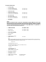
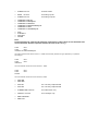
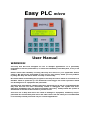
EASY PLC micro Specifications: Power Supply: 24VDC +/- 10% @250mA 5 Digital Inputs – 24 VDC (Logic 0 = 0 to 12VDC, Logic 1 = 18VDC to 30VDC) (2 High Speed Inputs for counting or encoder feedback – not tested/implemented) 4 Digital 24VDC / Analog Inputs 0-10VDC (13 bits resolution with DRE technology) 6 Digital Outputs 24VDC @0.5A / Optional 4A can directly drive solenoid valves Sink Type – Open Collector. Free Wheeling Diodes for inductive loads built in. (2 PWM outputs, can drive proportional valves, 1 PTO output for servo drive – not tested /implemented) 256 Memory Flags (240 General Purpose + 16 special Flags) 64 Timers (0.1 sec to 3276.7 sec) / Counters (0 to 32767) 128 Datawords for storage of parameter values / 64 datawords for temporary data 32 Messages for display of 16 characters each 64 subroutines with nesting depth of 8 routines Cycle time 4.6 milliseconds / 1000 statements approximately 2000 statements Program Memory Built in HMI – 16x2 LCD display + 16 key Keyboard 8 keys PB1 to PB8 can be used in PLC program Information display for status of Inputs and Outputs 1 x RS232 / RS485 port for interface to PC Execution Structure: The Easy PLC like almost all other PLCs operates in an infinite loop which has the following form. GET INPUTS EXECUTE LOGIC PROGRAM WRITE OUTPUTS The PLC reads all inputs. Then executes the logic program and generates outputs which are stored in the outputs image in the PLC memory. The outputs image is then dumped on to the terminals in the third and final step. The program execution loops back and executes the process infinitely.