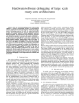
1
Digital Oscilloscope
Digital Oscilloscope
DECLARATION OF CONFORMITY
Manufacture's name
: EZ Digital Co., Ltd
Manufacture's Address
: 222-28, Nae-dong, Ojeong-gu,
Bucheon-si, Gyeonggi-do
R.O.KOREA, 421-160
Declares that the product
:
Product name
Model number
Date
: Oscilloscope
: DS - 1 XX X ( X : 0 ~ 9 )
: December, 01, 2001
Conforms to the following product specifications:
Safety : EN 61010-1 : 1993 + A2 : 1995
(IEC 10101 : 1990 + A1 : 1992
+ A2 : 1995, Modified)
EMC : EN 61326/1997 + A1:1998
Supplementary information:
The product herewith complies with the requirements of the
Low Voltage Directive 73/23/EEC and the EMC Directive 89/336/EEC
Bucheon, Gyeonggi
Cheol Young Kim
Quality Assurance Manager
Location
2
WARRANTY
This instrument is warranted against defects in workmanship and materials. If any
failure, resulting from a defect in either workmanship or material should occur under
normal use within a year from the original date of purchase, such failure will be
corrected free of charge to the purchaser by repair or replacement of the defective
part or parts. When the failure is a result of user's neglect, natural disaster or accident,
we charge for repairs regardless of the warranty period.
This warranty is subject to the following conditions and limitations.
The warranty is void and inapplicable if the defective product is not brought or sent
prepaid to our authorized service center or sales outlet within a warranty period.
Defective product is, on EZ Digital Co., Ltd.'s sole judgement, indemnified at a
purchased price, replaced with new one or repaired without charge or with charge.
In the event warranty service is needed, purchaser should get in touch with the service
center or sales outlet, or properly pack and return the product to the service center
or sales outlet at his or her own expense. A returned product must be accompanied
by a written description of the defect. We return the product to the purchaser at his or her
own expense.
In case the warranty does not cover the product on EZ Digital Co., Ltd.'s
sole judgement, we repair the product after obtaining prior permission from the
purchaser who received pro forma statement about repairing charges. In such a
case, EZ Digital Co., Ltd. bears the transportation expenses required to send back all the
repaired products temporarily, and then repair and transportation expenses will be
charged against the purchaser by the statement of accounts.
When the authorized sales agents sell our product, they must notify the purchaser of the
warranty contents, but have no right to stretch the meaning of original warranty contents
or offer additional warranty. EZ Digital Co., Ltd. does not provide any other promise or
suggestive warranty and holds no liability for the damage caused by negligence,
abnormal use or natural disaster. EZ Digital Co., Ltd. is not responsible for damages
though it was notified about the danger in advance.
For more information on service or overall repairs and maintenance of old and decrepit
products, be sure to contact our service center or sales outlet.
3
PRODUCT CONTENTS
OSCILLOSCOPE
- Set
1 set
SUPPLIED ACCESSORIES
- Operation manual
- Power cord
- 100MHz probes x1/x10
2EA (Only DS-1100)
OPTIONAL ACCESSORIES
- RS-232C thermal printer (Printy2 with RS-232C Cable)
- Test probes
150MHz probes x1/x10
250MHz probes x1/x10
- Service manual
- PC Software kit(RS-232C Cable, USB Cable, PC interface Program)
- Interface Card Type A (RS-232C, Centronics, USB)
- Interface Card Type B (RS-232C, Centronics)
4
CONTENTS
1. INTRODUCTION
...................................................................................7
1-1 KEY FEATURES ......................................................................................8
1-2 NOTES FOR A SAFETY OPERATION ..............................................9
1-2-1 OPERATING ENVIRONMENT ..........................................................9
1-2-2 SAFETY SYMBOLS .........................................................................9
1-2-3 POWER SOURCE-RELATED WARNINGS ....................................10
1-2-4 PLACE-RELATED WARNINGS ......................................................10
1-2-5 OPERATION-RELATED WARNINGS .............................................11
1-2-6 SERVICE-RELATED WARNINGS ..................................................12
1-2-7 CLEANING AND MAINTENANCE .................................................13
1-3 NOTES TO USERS ................................................................................14
1-3-1 NOTICE FOR PROPER MEASUREMENT .....................................14
1-3-2 WHEN CONNECTING PERIPHERAL DEVICES .......................... 15
1-3-3 PROBE ........................................................................................... 18
1-4 INSTALLATION ..................................................................................... 20
1-4-1 POWER CODE ................................................................................ 20
1-4-2 INTERFACE CARD .......................................................................... 20
2. DESCRIPTION
.................................................................................... 22
2-1 KEY & DISPLAY DESCRIPTION ..................................................... 23
2-1-1 DISPLAY OVERVIEW .................................................................... 23
2-1-2 VERTICAL AXIS OPERATION ...................................................... 25
2-1-3 HORIZONTAL AXIS OPERATION ................................................. 26
2-1-4 TRIGGER ........................................................................................ 27
2-1-5 MENUS ........................................................................................... 28
2-1-6 CONNECTORS .............................................................................. 29
2-1-7 THE MENU BOX BUTTON AND FUNCTION KNOB ..................... 29
2-2 MENUS .................................................................................................... 30
2-2-1 AUTOSET .......................................................................................30
2-2-2 VERTICAL ......................................................................................31
2-2-3 MATH ............................................................................................. 33
2-2-4 HORIZONTAL ............................................................................... 37
2-2-5 TRIGGER ....................................................................................... 38
5
2-2-6 MEASURE ..................................................................................... 43
2-2-7 SAVE/RECALL .............................................................................. 45
2-2-8 ACQUIRE ....................................................................................... 47
2-2-9 CURSORS ..................................................................................... 49
2-2-10 UTILITY ........................................................................................ 51
2-2-11 DISPLAY ...................................................................................... 53
2-2-12 HARDCOPY ................................................................................. 55
2-3 USING THE FUNCTIONS EFFECTIVELY ...................................... 56
2-3-1 USING THE ZOOM FUNCTION .................................................... 56
2-3-2 USING THE SINGLE FUNCTION .................................................. 57
2-3-3 USING FFT (FAST FOURIER TRANSFORMATION) .................... 58
3. APPENDIX
............................................................................................. 60
3-1 SPECIFICATIONS ................................................................................ 61
3-2 FACTORY DEFAULTS ........................................................................ 65
6
1. INTRODUCTION
7
1-1 KEY FEATURES
The 16bit high speed microprocessor adoption enables the scope to acquire
a typical 100,000 points per second and quickly update the picture on
the screen.
Basic memory length of DS-1150 is 10kB and that of DS-1150 & DS-1250 is 32kB.
Captured waveforms can be zoomed in and analyzed in detail. Also its built-in
10ns peak detection circuit enables it to capture high frequency noise even at
a low speed time/div and magnify and analyze it using the zoom-in function.
In addition, it can save up to 10 waveforms and provide diversified analysis
function like FFT which is available on high priced products.
General Features
- 100MHz bandwidth(DS-1100), 2 CH dual digitizer
- 150MHz bandwidth(DS-1150), 2 CH dual digitizer
- 250MHz bandwidth(DS-1250), 2 CH dual digitizer
- 100MS/s simultaneous maximum sampling rate per channel,
200MS/s sampling rate for one channel only
25GS/s equivalent sampling rate per channel
- 10ns peak detection for glitch capture even in ROLL mode
- Max. 400Vpk input voltage into all channels
Convenient Functions
- Direct single trigger capture function using a hot-key
- Simultaneous 5 waveform informations auto measurement and FFT analysis
- Auto trigger level setting to 50%
- Saving 10 waveforms & 10 setup parameters
- Convenient inserting interface card for RS-232C, hardcopy and USB
8
1-2 NOTES FOR A SAFETY OPERATION
1-2-1 OPERATING ENVIRONMENT
This instrument will operate to its specifications if the environment is
maintained within the following conditions.
- Indoor use
- Altitude up to 2000m use
- Operating temperature 0 ~ 40
- Relative humidity 80%
- Main supply voltage fluctuations not exceed 10% of the nominal voltage.
- After turning on the instrument, please allow a pre-heating period of as long
as some 15 minutes.
This instrument has been qualified to the following EN61010-1 Category :
- Installation (Over-voltage) category 2
- Pollution Degree 2
1-2-2 SAFETY SYMBOLS
Where these symbols or indications appear on the instrument or in this
manual, they have the following meanings.
Refer to accompanying documents for Safety-related information.
Wherever the symbol is present, see "NOTES FOR A SAFETY OPERATION"
part in this manual.
Ground
Risk of hazard which may cause injury to human body or danger to life.
If a WARNING appears on the instrument , and in this manual, do not
proceed until its suitable conditions are understood and met.
Risk of hazard which causes fire or serious damage to the instrument or
other equipment. Do not proceed until its suitable conditions are met.
9
1-2-3 POWER SOURCE-RELATED WARNINGS
Protection of Power Cord and Unplugging
Power-supply cords should be routed so that they are not likely to be waked
on or pinched by items placed upon or against them, paying particular
attention to cords at plugs, convenience receptacles, and the point where
they exit from the instrument. For added protection for this instrument during
a lightening storm, when it is left unattended and unused for long periods
of time, unplug it from the power source. This will prevent damage to the
instrument due to lightening and power-line surges.
Overloading
Do not OVERLOAD power source and extension cords as this can result in a risk
of fire or electric shock.
1-2-4 PLACE-RELATED WARNINGS
Object and Liquid Entry
Never push objects of any kind into this instrument through openings as they
may touch dangerous voltage points or short out parts that could result in a
fire or electric shock. Never spill liquid of any kind on the instrument. Do not
use this instrument near water- for example, near a bath tub wash bowl,
kitchen sink, or laundry tub, in a wet basement, or near a swimming pool, and
the like. Keep the instrument away from damp air, water and dust.
Unexpected trouble may be caused when the instrument is placed in a damp
or dusty place.
FLAMMABLE AND EXPLOSIVE SUBSTANCE
Avoid using this instrument where there are gases, and where there are
flammable and explosive substances in the immediate vicinity.
Unstable Location
Do not place this instrument on an unstable cart, stand, tripod, bracket, or
table. The instrument may fall, causing serious injury to a person, and serous
damage to the instrument. Do not place or use the instrument in a place
subject to ventilation.
10
1-2-5 OPERATION-RELATED WARNINGS
Power Switch
Before plugging the power cord in be sure to check that the power switch is
set to off for protection of the instrument.
Ground Connection
When connecting a probe , connect the ground side of the probe to the ground
of the signal source. At a floating status, a potential might be produced with
respect to other devices or ground, resulting in damaging the instrument,
probe, other measuring instruments, etc.
GND
CH 1
Excessive Input Voltage
In order to avoid electric shock or fire, the input voltages to the probes, BNC
connectors are specified as follows. Do not apply higher voltages. Before using
probe, check the rated voltage with the naked eye. Remove the unused probe
not to contact with ambient high voltage parts. If you apply a higher voltage
more than 400Vpk , remove the probe out of BNC terminals to ensure against
accidental danger
Maximum input Voltage
- CH1, CH2 all 400Vpk
Do not Use Non-certified Probes
Use the probes certified according to EN 61010-1 and EN 61010-2-031 in europe.
Use the UL listed probes in america.
11
1-2-6 SERVICE-RELATED WARNINGS
Damage Requiring Service
Do not attempt to service this instrument yourself as opening or removing
covers may expose you to dangerous voltage or other hazards.
Unplug this instrument from the power source and after servicing to
qualified service personal under the following conditions
- When the AC power cord or plug is damaged.
- When the LCD is damaged, you must not open the cover during operation.
There is a risk of electric shock.
- If liquid has been spilled, or objects have fallen into the instrument.
- If the instrument does not operate normally by following the operating
instructions. Adjust only those controls that are covered by the operating
instructions as an improper adjustment of other controls may result in
damage and will open require extensive work by a qualified technician to
restore the instrument to instrument to its normal operation.
Unplug the power cord from the power source before opening the cover, and
then remove the probe. Even if the instrument is disconnected from all the
power sources, special attention is required in service as the inside capacity
might be in charged condition. When replacement of fuses or other parts is
required, be sure the service technician has used replacements parts specified
by the manufacturer or have the same characteristics as the original part.
Unauthorized substitutions may result in fire, electric shock or other hazards.
There is a risk of electric shock. No user
serviceable parts inside. Leave repair to
qualified personnel.
Safety Check
Upon completion of any service or repairs to this instrument, ask the service
technician to perform safety checks to determine that the instrument is proper
operating condition.
12
1-2-7 CLEANING AND MAINTENANCE
Maintenance routines performable by the operator are listed in this section.
More advanced routines (i.e., procedures involving repairs or adjustments
within the instrument) should be referred to service personnel.
Cleaning
If the outside of the case becomes dirty or stained, carefully wipe the surface
with a cloth moistened with detergent, then wipe the cleaned surface with a
dry cloth. In case of severe stain, try cleaning with a cloth moistened with
alcohol. Do not use powerful hydrocarbons such as benzene or paint thinner.
Dust and/or smudges can be removed from the LCD screen. First remove the
front case and filter. Clean the filter (and the LCD face, if necessary) by wiping
carefully with a soft cloth or commercial wiping tissue moistened with a mild
cleaning agent. Take care not to scratch them. Do not use abrasive cleanser
or strong solvents. Let the cleaned parts dry thoroughly before reinstalling
the filter and front case. If it is installed wet, dew may form and blur the
waveforms. Be particularly careful not to get fingerprints on the filter or LCD
face.
MENU
MENU
Maintenance
This instrument should never be placed in a built-in installation such as a
bookcase or rack unless proper ventilation is provided. Ideal ambient
temperature and relative humidity for storing the instrument are 23 and 60%
13
1-3 NOTES TO USERS
1-3-1 NOTICE FOR PROPER MEASUREMENT
It is recommended to allow about 15 minutes after power on as warm up time
before starting measurement. Traces may drift a little just after power on.
When measuring a signal with high accuracy trace declination, you can correct
the trace position using the automatic calibration function.
Before starting up this function, allow enough warm-up time.
The calibration is classified into software calibration for resorting to the
automatic calibration function in the menu, and hardware calibration for
optimizing the internal circuitry in a wide range.
1. The software calibration is recommended when the ambient temperature
has excessively changed (5 ) or when 1000 operating hours or 6 months
has been attained. If the trace is displayed excessively or when it is desired
to optimize the measurement, execute it referring to the automatic
calibration. Before calibration, disconnect all inputs for accurate adjustment.
2. The hardware calibration is necessary to keep the instrument to a stable
operation status. It is recommended to adjust the instrument every 2,000
operating hours or every year.
SOFTWARE CALIBRATION FOR OPTIMUM MEASUREMENT
The changes in measurement accuracy due to use environments
(temperature, humidity, etc) can be optimally corrected automatically
by activating the calibration. It is recommended to perform calibration
when any of the following cases applies.
- Before a customer starts to use this instrument first
- When an ambient temperature changes more than 5 , compared
with that at the time of the previous calibration.
- Every 6 months or 1000 operating hours
- Optimization of measurement accuracy is required
14
1-3-2 WHEN CONNECTING PERIPHERAL DEVICES
When connecting a printer and a personal computer to the oscilloscope, be
sure that the oscilloscope, the printer and the personal computer are all off,
and then connect them. Pay attention to the direction of the cables and the
ports of the peripheral devices. Before operation, be sure to carry out the
setting necessary for the printer and the personal computer. (For the setting
of the printer and the personal computer, refer to the operation manual for
each) If you operate the printer and the personal computer which are
improperly set, abnormal operation will occur. In this case, turn off the
instrument, the printer and the personal computer at once, and set them
properly again and operate them.
Before using peripheral devices, Interface card should be installed in this instrument.
When using thermal printer opertion, RS-232C settings are as follows
- BAUD RATE : 9600 bps
- PARITY BIT : None
- DATA BIT : 8 bit
* RS-232C Serial cable is 9pin
(male) to 25pin(male) null cable.
* RS-232C thermal printer is
Printy 2 of SANEI Electric INC
15
When using printer operation, Centronics settings are as follows
* This instrument supports
DeskJet and LaserJet with
PCL level 3
* DeskJet , LaserJet is
registered trade mark of HP.
K.I.S
When using PC communication operation, RS-232C settings are as
follows
Before communicating with a PC, the PC software kit(option) should be
installed in your PC. If you want to have more detailed information, refer to the
PC software kit manual.
16
When using PC communication operation, the USB settings are as follows
Before communicating with a PC, the PC software kit (optional) should be
installed in your PC, and the interface card with USB should be installed in
your instrument. The USB protocol is spec V1.1
For more detailed information, refer to the PC software kit manual.
If users want to connect the instrument with the computer and use it, the port
needs to be set to the connection format between them and the transmission
format needs to be set to the BMP format.
17
1-3-3 PROBE
The first step of measurement is to connect the signals to the instrument
properly.
GROUND CLIP
BODY
HOOK COVER
CAPACITANCE
CORRECTION
TRIMMER
GROUND
COVER
RETRACTABLE
HOOK TIP
Probe Attenuation Setting
When the optional probe is used with the x10 / x1 select switch set to x10,
the input signal to the instrument is attenuated to 1/10. When a signal is
too small to be measured with x10, use the mode x1. In this case, note
that the input impedance of x1 is different from that of x10, and the measurable frequency band becomes very low.
Attenuation switch
Probe Grounding
Connect the probe ground lead as close as possible to the point being
measured especially when measuring a signal with a fast rise time or a
high frequency signal. Long probe ground leads may cause waveform
distortions, such as ringing and overshoot.
CH 1
Spring GND
18
Probe Compensation
The probe switch setting is 10X.
To avoid a measurement error, probe
compensation must be done. Especially when
the probe is charged.
Connect the probe tip to the CAL 1V output
terminal. A 1 kHz square wave should be
displayed with flat tops.
Any distortion in the left presentation is
caused by incorrect probe compensation.
If overshoot or undershoot is present, turn the
screwdriver adjustment in the probe for a
flat-top presentation.
This adjustment remains in effect until changed
again.
Be sure that the attenuation switch on the
probe is set to match with the probe menu
selection in the oscilloscope.
CORRECTLY
COMPENSATED
UNDER
COMPENSATED
OVER
COMPENSATED
PROBE COMPENSATION BY CORRECTION SQUARE-WAVE
19
1-4 INSTALLATION
1-4-1 POWER CORD
Use only power cords designed for your oscilloscope. Use a power source
that delivers 90 to 250 VACRMS, 48 to 440 Hz.
1-4-2 INTERFACE CARD
You can increase the feature set of your oscilloscope by inserting an interface
card.
Refer to the "NOTES TO USERS" section in this manual and the PC software
Kit manual for detailed description. Install the interface card into the rear of
DS-1000 series as following procedures.
Two types of interface card (optional) are available. Be sure of which one you
need when you place an order.
20
21
2. DESCRIPTION
22
2-1 KEY & DISPLAY DESCRIPTION
2-1-1 DISPLAY OVERVIEW
1. TRIGGER MODE.
2. TRIGGER SOURCE.
3. TRIGGER SLOPE.
4. TRIGGER COUPLING MODE.
5. RUN / STOP.
6. CH VOLTS / DIVISION.
7. TIME / DIVISION.
8. VERTICAL POSITION VALUE.
9. TRIGGER LEVEL VALUE.
23
10. CH1 / CH2 POSITION CURSOR.
11. TRIGGER LEVEL CURSOR.
12. HORIZONTAL TRIGGER POSITION.
13. INPUT COUPLING MODE.
24
2-1-2 VERTICAL AXIS OPERATION
VOLTS/DIV (CH1, CH 2). Adjusts vertical scale factor of the scope waveform.
CH 1, CH 2 MENU. Shows the channel function and channel waveform
display on and off.
MATH MENU. Shows the math function.
CH 1, 2 POSITION. Adjusts vertical position of the scope waveform.
25
2-1-3 HORIZONTAL AXIS OPERATION
MENU
TIME/DIV. Adjusts horizontal axis scale factor of the scope.
HORIZONTAL MENU. Shows the horizontal function.
POSITION. Moves horizontal axis position of the scope.
26
2-1-4 TRIGGER
TRIGGER MENU. Adjust the trigger mode.
TRIGGER SOURCE. Select the trigger signal source.
SET LEVEL TO 50%. Set the trigger level to the middle of the scope waveform.
TRIGGER LEVEL. Selects a starting point of triggered signal.
27
2-1-5 MENUS
MEASURE. Controls the measurement functions.
SAVE/RECALL. Controls the save/recall functions.
ACQUIRE. Controls the acquire mode.
CURSORS. Controls the cursor functions.
UTILITY. Sets the utility functions.
DISPLAY. Sets the display mode.
AUTOSET. Automatically displays the optimum waveform of input signals.
HARDCOPY. Prints the waveform.
RUN/STOP. Controls the waveform acquisition.
SINGLE. Captures a non-periodic signal and a long-periodic signal.
28
2-1-6 CONNECTORS
This outputs squre wave(1V, 1kHz) for the probe compensation.
CH 1, CH 2.
Connects input signal to the channel vertical amplifier. CH1 becomes a signal
of X -axis during X-Y operation and CH2 becomes a signal of Y-axis during
X-Y operation.
EXT TRIG.
Connects a external trigger signal to the trigger circuit.
.
2-1-7 THE MENU BOX BUTTON AND FUNCTION KNOB
When you press a menu button on the front panel, the associated menu title
displays at the top right screen. There can be up to five menu boxes below the
menu title. To the right of the each menu box is bezel button you can use to
change the menu setting.
29
2-2 MENUS
2-2-1 AUTOSET
AUTOSET
The front panel setting are automatically
performed so that the optimum waveform
is displayed for an input signal and
changes itself in succession. With this
function, the following items can be
automatically set according to the
characteristics of an input signal.
FunctionSetting
Vertical coupling
Trigger type
Trigger coupling
Trigger slope
Trigger mode
Setting
AC
Edge
Adjusted to DC
Rising
Auto
Condition
The autoset function is available only for a stable, repetitive input signal. For
a stable operation, an input signal is essential to meet the following conditions.
a) Frequency : 50Hz ~ maximum bandwidth, typical
b) Amplitude : more than 60mV
If these conditions are not satisfied, the following message is diaplayed
below the screen : " Unable to autosetup "
30
2-2-2 VERTICAL
Following description on switches are applied to both CH1 And CH2 equally.
VOLTS/DIV
The vertical axis sensitivity can be set
by the VOLTS/DIV switch of the
Ch1 and CH2.
MENU
There is a separate vertical menu for each
channel. Each item is set individually for
each channel.
31
1)Display. (On/Off) : CH1 or CH2 is selected and displayed
by pressing this switch, and both channels can be selected and displayed at
the same time. Whenever this switch is pressed, channel display function is
operated repeatedly.
2)Coupling. (AC/DC/Ground) : Three input coupling modes are
available. Select the desired coupling mode by the DC/AC/GND switch. The
selected coupling mode is displayed at the bottom left of the screen. Whenever
the switch is pressed, coupling of input signal is operated in the sequence of
AC, DC and Ground.
AC
: Displayed on the screen in the form of " ". An input signal is
connected to the amplifier via a capacitor. Its DC component is cut
and only AC component is displayed.
DC
: Displayed on the screen in the form of " " . An input is directly
connected to the amplifier, and the signal including a DC component
is displayed.
Ground : Displayed on the screen in the form of " " . An input signal is
separated and the input of the vertical amplifier is grounded.
3)Probe . (X1 / x10 / x100 / x1000) : Set this to match your probe
attenuation factor to make the vertical scale readout correct
x1
: when 1:1 probe is used or signal is directly connected to the coaxial
cable, x1 is selected
x10
: when 10:1 probe is used , x10 is selected.
x100
: when 100:1 probe is used, x100 is selected.
X1000 : when 1000:1 probe is used , x1000 is selected.
4)Position Set To 0
Set the offset to 0V. Offset pertorms a function similar to the vertical position
knob.
32
POSITION
The displayed waveform can be moved up
and down by the position knob.
When the knob moves to right, waveform
moves down and when the knob moves to
left, waveform moves up.
2-2-3 MATH
MATH
When this switch is pressed, arithmetic
and advanced function are displayed.
33
1) Arithmatic
(Off/Ch1+Ch2/Ch1-Ch2/Ch2-Ch1/Ch1 Invert/Ch2 Invert)
Addition, subtraction and
inversion arithmetic of the
two channels are able to
be carried out to Ch1 or
Ch2 by Arithmatic.
Off
: This cancels the arithmatic function.
Ch1 + Ch2 : This displays a waveform which adds signals of two channels.
Ch1 - Ch2 : This displays a waveform which subtracts Ch2 from Ch1.
Ch2 - Ch1 : This displays a waveform which subtracts Ch1 from Ch2.
Ch1 Invert : This displays an inversed waveform signal of Ch1.
Ch2 Invert : This displays an inversed waveform signal of Ch2.
Displaying a math waveform automatically removes the display of channels
used to create the math waveform. Math operations are turned off if a channel
used in the operation is turned on.
2) Advenced Functuons(Off/Pass-Fail/FFT)
34
Off
: This cancels the Advanced functions.
Pass-Fail : User sets the judgement range of Pass-Fail displayed on the
screen and compares it with acquired waveforms. When this
menu is selected, submenu On, Off, Ch1, Ch2 and Edit are
displayed. This function is automatically canceled when XY
format display is operated, AUTOSET is operated, Measure
menu is operated, ROLL mode is operated, Arithmatic function
is operated or Cursor function is operated.
Source (Ch1/Ch2)
Ch1
: Be selected judgement area as "to be edited signal source"
and "to be compared signal source".
Ch2
: Be selected judgement area as " to be edited signal source"
and "to be compared signal source".
Zone Edit (Off/Upper Side/Lower Side/Done)
Off
: This clears all judgement area currently set on the screen
and cancels comparing function. But the data in the memory
are not cleared.
Upper Side : This decides to be edited portion from upper portion of the
waveform. The edited portion be adjusted to use function
knob. And it only moves to the upper side of the reference
waveform. This mode don't use the others menu except the
function knob.
Lower Side : This decides to be edited portion from lower portion of the
waveform. . The edited portion be adjusted to use function
knob. And it only moves to the lower side of the reference
waveform. . This mode don't use the others menu except the
function knob.
Done
: This performs a operation of comparing judgement area set
by user with acquired waveform. When acquired waveform is
in judgement area, RUN is maintained, and when acquired
waveform is get out of the judgement area, STOP is displayed
and waveform is stopped. When comparing function is
necessary again, maintain RUN by pressing RUN/STOP switch.
The waveform is regenerated when selecting On after setting
Off
35
Off/On
Off : Selects not to activate PASS-FAIL function.
On : Selects to activate PASS-FAIL function.
FFT
This allows acquired
waveforms to be converted
into frequency-domain
traces, revealing valuable
spectral information that
would otherwise be
impossible to detect on a
time-domain record.
Source(Ch1/Ch2)
Ch1 : Ch1 is selected source as to be transformed FFT.
Ch2 : Ch2 is selected source as to be transformed FFT.
Window(Rectangle/Hamming/Hanning)
Rectangle : Transforms to rectangular mode.
Hamming : Transforms to hamming mode.
Hanning
: Transforms to hannig mode.
Execute/Calculating
Execute
: Calculates the FFT. After calculate, display of the waveform is
stopped.
Calculating : Displays the status of calculating.
36
2-2-4 HORIZONTAL
MENU
TIME/DIV.
A time axis range can be set by the
TIME/DIV knob. When the knob turn
to 5s, TIME/DIV is slow in and turn
to 2ns, TIME/DIV is fast in.
MENU
Set the horizontal menu
MENU
Time Reference (Center/Right/Left)
Control position of horizontal trigger.
Center : Set the position of horizontal trigger to the center of screen.
Right : Set the position of horizontal trigger to the right of screen.
Left
: Set the position of horizontal trigger to the left of screen.
POSITION
Displayed waveform can be moved left
and right.
MENU
37
2-2-5 TRIGGER
MENU
Two types of triggering are available:
Edge and TV. A different set of menus
display for each trigger type.
1)Type(Edge/TV) : Edge
Use edge triggering to trigger on the edge of the input signal at the trigger
threshold.
Coupling(AC/DC/HF Reject/LF Reject) : This function decides which
part of the signal is transferred to the trigger circuit. That is, desired coupling
type is selected between trigger source signal and trigger circuit by this switch.
When coupling switch is pressed, AC, DC, HF Reject and LF Reject are
displayed in sequence.
38
AC : Only AC component is passed through in the signal and DC
component Is removed from the trigger signal.
DC : Trigger signal which includes DC signal is coupled. Trigger is applied
when DC level of signal intersects with setting trigger level.
HF Reject (High frequency rejection) : This function interrupts a high
frequency component of triggering signal. So, only the low frequency
component is passed through triggering system and then captured.
Interruption of high frequency reduces a signal with 300kHz or more.
LF Reject (Low frequency rejection) : This function interrupts low
frequency component of triggering signal. Interruption of low frequency
reduces a signal with 1kHz or less.
Slope(Rising/Falling) : This function decides at which place the trigger
point is found out, rising edge or falling edge. This function displays a status
of slope setting behind "coupling". Screen display of rising edge is " " and
falling edge is " "
Mode(Auto/Normal/Single) : When MODE function is pressed, AUTO,
NORM and SINGLE are displayed in sequence. Setting of trigger mode is
displayed at the top left of the screen.
Auto : Without trigger, waveform is able to be captured by this function.
When AUTO mode is triggered forcibly without triggering, note that
It is not synchronized with the waveform of display. In other words,
successive capture is not triggered at same point on display.
Therefore, waveform seems to cross and roll on the screen.
Normal : When Trigger is operated, oscilloscope is able to capture the
waveform by this function. Without trigger , oscilloscope does not
capture the waveform.
Single : Trigger is able to be operated with NORM mode. However,
when trigger is operated in long period or non-periodic signal, it is in the
status of STOP, and when trigger is not operated, oscilloscope is
In stand-by status until the trigger is restarted.
39
2)Type(Edge/TV) : TV
Use TV triggering to trigger on the TV signal.
Sync(Line/Field)
Line : This function is solely used in the observation of TV signal
and trigger is applied to horizontal synchronization signal.
Field : Trigger is applied to vertical synchronization signal.
40
SOURCE
With this function, Trigger is able to be
selected from the source such as CH1,
CH2, EXT or LINE. The channel which is
selected as trigger source performs a
function of trigger source without
connections with display. After the display
of "mode setting",source setting is
displayed on screen.
CH1 : Input signal of CH1 is used as trigger source.
CH2 : Input signal of CH2 is used as trigger source.
EXT : When trigger is operated with signals from external clock or other parts
of the circuit, or in case an auxiliary trigger is used, connect the external
trigger signal to the EXT terminal.
LINE : The LINE trigger source uses the line voltage signal as the trigger source.
SET LEVEL TO 50%
This function automatically sets a trigger
source signal within the 50% of trigger
level range. When trigger coupling is AC
or LF Reject, the 50% of trigger level is set
at the center of GRID vertical axis. When
trigger coupling is DC or HF Reject, it is set
at the 50% of trigger source signal
amplitude.
41
LEVEL
With this function, trigger level is adjusted
to the signal level before entering into
triggering. Trigger point decides a
occurring point on edge. When the knob
turn to the right, edge level moves up and
turn to the left, edge level moves down.
42
2-2-6 MEASURE
MEASURE
Push the MEASURE button to access
the automated measurement capabilities.
It has the ability to display up to five
parameters at a time. When this menu is
selected, submenu NONE, Pk-Pk, RMS,
Mean, Frequency, Rising Time, Falling
Time, Period, +Width, -Width and Duty are
displayed.
NONE : This cancels the measuring
functions of parameter.
Pk-Pk : This displays a Peak to Peak value of the waveforms of the currently
displayed channels. That is, absolute gap between maximum and minimum
amplitude is displayed with volt. When input signal is out of the ADC input
range , "?" is displayed.
Maximum value and minimum value are equal, "Invalid" is displayed.
RMS : This displays a Root Mean Square value of 1 cycle of the waveforms
of currently displayed channels. When range of input signal is out of the
ADC input range, peak to peak value is less than 2 division, or width of
1 cycle is less than 0.4 division on display, "?" is displayed. When 1 cycle is
not captured, "Invalid" is displayed.
Mean : This displays a mean value of 1cycle of currently displayed
waveforms. When range of input signal is out of the ADC input range,
peak to peak value is less than 2 division, or width of cycle is less than
0.4 division on display, "?" is displayed. When 1 cycle is not captured, "Invalid"
is displayed.
Frequency : This displays a frequency value of 1 cycle of currently
displayed waveforms. When range of input signal is out of the ADC input
range, peak to peak value is less than 2 division, or width of 1 cycle is less
than 0.4 division on display, "?" is displayed. When 1 cycle is not captured,
"Invalid" is displayed.
43
Rising Time : This displays a rising time of currently displayed waveforms.
When range of input signal is out of the ADC input range, peak to peak value is
less than 2 division, or width of 1 cycle is less than 0.4 division on display, "?" is
displayed. when 1 cycle is not captured, "invalid" is displayed.
Falling Time : This displays a falling time of currently displayed waveforms.
When range of input signal is out of the ADC input range, peak to peak value is
less than 2 division, or width of 1 cycle is less than 0.4 division on display, "?" is
displayed. When 1 cycle is not captured, "Invalid" is displayed.
Period : This displays a period of 1cycle of currently displayed waveforms.
When range of input signal is out of the ADC input range, peak to peak value is
less than 2 division, or width of 1 cycle is less than 0.4 division on display.
When 1 cycle is not captured, "Invalid" is displayed.
+ Width : This displays a positive width of 1 cycle of currently displayed
waveforms. When range of input signal is out of the ADC input range, peak to
peak value is less than 2 division, or width of 1 cycle is less than 0.4 division on
display, "?" is displayed. When 1 cycle is not captured, "Invalid" is displayed.
- Width : This displays a negative width of 1 cycle of currently displayed
waveforms of channel. When range of input signal is out of the ADC input range,
peak to peak value is less than 2 division, or width of 1 cycle is not captured,
"Invalid" is displayed.
Duty : This displays a duty ratio of 1 cycle of currently displayed waveforms
of channel. When range of input signal is out of the ADC input range, peak to
peak value is less than 2 division, or width of 1 cycle is less than 0.4 division on
display, "?" is displayed. When 1 cycle is not captured, "Invalid" is displayed.
44
2-2-7 SAVE/RECALL
SAVE/RECALL
This function is able to save waveforms
and setup conditions of present working
environment and they can be recalled by
the user. It is used in setting simple working
environment and for waveform comparison.
The saved information could be preserved
for a time even if the inside battery is
completely discharged or disconnected from
the main body.
1)Type(Setups/Waveforms) : Setups
This operates the function to save present working condition
into memory space.
Setup(0/1/2/3/4/5/6/7/8/9) : The menu displays the memory space to save
information, and it is able to save upto 10 seup conditions They don't be
overlapped with memory space for waveforms.
45
Save : The saved setup information includes the conditions of input coupling,
display, volts division, trigger mode, trigger coupling, trigger source, trigger
slope, trigger level, cursor information, probe factor, LCD brightness, display
format, display type, acquisition type and interface card setup.
Recall : Recalls the instrument settings stored in the location chosen in the
setup space.
Recall Factory: You can recall the default Factory Setup to initialize the
instrument to a known setup.
2)Type(Setups/Waveforms) : Waveforms
This operates the function to save waveform being displayed at present into
memory space.
Reference(0/1/2/3/4/5/6/7/8/9) : This function displays the memory space
to save waveforms, and it is able to save 10 waveforms . The memory space
don't be overlapped with that for setup condition.
Save : Stores the source waveform to the chosen reference location.
Recall : Turns the reference waveform display on or off.
On : you will be in the mode from which the waveform was saved.
Off: This menu operates to cancel present displayed waveforms and to
return to the former waveforms.
Source(Ch1/Ch2) : Choose the waveform source to store.
46
2-2-8 ACQUIRE
ACQUIRE
Push the ACQUIRE button to set
acquisition parameters.
1)Peak detect(Off/On)
Off
On
: Cancels the peak detect mode.
: Acquires the peak value of the input signal. This mode is able to
detect glitches.
2)Average(Off/2/4/8/16/32/64/128)
In this mode, next signal is doubled as much as the reciprocal number of
average frequency from the current signal. This mode is used to reduce a
distortion of display resulting from noise in signal. The numbers next to Avg
are weighted value.
47
3)Persist(Off/On)
Refresh or overwrite mode is able to be selected by Persist.
Off : This selects refresh display mode. In this mode, only the newly acquired
data are displayed.
On : This selects overwrite display mode. In this mode, newly acquired data
are displayed upon previously acquired data. This mode is used to
observe noise of signal, etc.
48
2-2-9 CURSORS
CURSOR
The user can operate the cursor by himself
and measure the voltage or time of
displayed waveform. These functions can
be stopped or canceled automatically in
the modes of MEASURE, PASS-FAIL
setting, XY format.
1)Type(Off/Voltage/Time)
This is used to set the type and on/off mode of cursor. Pressing this button,
OFF, Voltage and Time are changed in sequence. At every time, present
measuring value is showed up at the menu display.
Off : This cancels the cursor mode
Voltage : Measuring the voltage of vertical parameter. Two horizontal
cursors show up.
Time : Measuring the time of horizontal parameter. Two vertical cursors
show up.
2)Source(Ch1/Ch2) : Choose the waveform on which to take the
cursor measurement.
49
3)Cursor 1
Displays cursor 1 location.
4)Cursor 2
Displays cursor 2 location.
5)Delta
Display the gap between cursors .Use the function knob to move the
cursors. You can move the cursors only while the cursor menu is
displayed.
50
2-2-10 UTILITY
UTILITY
Push the UTILITY button to display the
UTILITY menu. The UTILITY menu is
changed with the addition of interface
modules.
The menu explained here relates to the
product without module installed. Refer
to the manual supplied with your interface
module for items not discussed here.
1)System Status
Selecting System Status from the utility menu displays the menus available
for obtaining a list of control settings for each group of instrument controls.
51
Vertical : Lists vertical parameters of channels.
Horizontal : Lists horizontal parameters of channels.
Trigger : Lists trigger parameters
Misc : Shows the information. That is the software version and processor
release level. If the option module is installed, the setting of RS-232C
and the setting of hardcopy are add.
SVC : This menu is only used for the service engineer.
2)Options : This menu changes with the addition of option modules. The
menus explained here relate to the product with no modules installed. Refer
to the manual supplied with your option module for items not discussed here.
3)Do Self Calibration : To operate calibration , " Do Self Calibration"
is selected. In order to perform proper correction, be sure to remove all the
input signals and probe of input connector before carry out above function.
52
2-2-11 DISPLAY
DISPLAY
Push the DISPLAY button to choose how
waveforms are presented and to change
the appearance of the entire display.
1)Type(Dots/Vectors)
This selects connection mode of acquired waveform data
Dots : Acquired waveform data are displayed on the screen only in the form
of dots.
Vectors : Dots of the acquired waveform data form a line and are displayed
on the screen. As dots form a line, square waveform signal or rising edge of
pulse is able to be easily observed. This is not operated in XY format mode.
2)Format(YT/XY) .
Display mode of waveform is selected by format.
YT : This is a normal type of display and shows a change of signal with the lapse
of time.
XY : User compares waveforms of two channels by dots and is able to get phase
difference between the signals. Using this menu.
53
3)Grid(Full/Cross/Board) .
This menu sets the type of measuring grid.
Full : Frame, axis and grid are all displayed. By using this scale, adjust
waveform to the scale and then measure the value of the waveform data.
Cross : Frame and axis are displayed. Cross measures a waveform by
moving a waveform to the center of the screen.
Board : Only the frame is displayed. When scale is not necessary in
measuring the data value of the waveform, or when cursor or field display is
not necessary, this mode is selected.
4)Contrast Increase .
Brightness of LCD is brightened by the stage of 5%.
5)Contrast Decrease .
Brightness of LCD is darkened by the stage of 5%.
6)FUNCTION KNOB
Brightness of LCD is changed by the stage of 1%.
54
2-2-12 HARDCOPY
HARDCOPY (Need Interface Card)
Push the HARDCOPY button to print a
hard copy of the display. The hardcopy
function requires that an interface card
with Centronics or RS-232C be installed
and connected to a printer.
Refer to the manual supplied with your
interface card for instructions on
connecting and using the interface card.
To use Hardcopy, the instrument needs to be set appropriately. The setting
can be adjusted under "Options" in the "Utility"menu. Detailed information
about setting the menu can be referred to "NOTES TO USERS".
Hardcopy supports 3 types: BMP, Centronics, Thermal.
BMP - BMP type is enabled only when used to interface with the PC. To use
BMP as a Hardcopy, required are additional programs that enables the
PC to receive and save the BMP format. Using EZ Digital's Softview
will facilitate saving in the BMP format with ease and convenience.
RS232C and USB are both supported, but USB is faster in saving.
Softview operates under Windows 98/2000.
Centronics - Centronics type is needed to send the screen data to a printer
directly. Centronics type supports HP's PCL level 3 Deskjet and Laserjet
printers in general. Even if the brand differs, if the printer has a mode
compatible with the PCL level 3 or lower, it's possible to use. Most
printers support this format. However, printers that provide the PCL
format only through software on PCs and the HP 700 printer series are
not supported. Concerning detailed information for PCL format
availability, refer to the printer user's manual or visit the printer maker's
homepage
Thermal - Thermal type is enabled only by using SANEI's Printy2
thermal printer that supports RS-232C interface.
55
2-3 USING THE FUNCTIONS EFFECTIVELY
2-3-1 USING THE ZOOM FUNCTION
First of all, set oscilloscope to be in stop status by using RUN/STOP button.
When you change time/div rotary switch in stop status, waveform is zoomed in.
Following figures show zoom function.
When Oscilloscope is RUN status,
Push RUN/STOP button.
Oscilloscope will be in STOP status.
Use TIME/DIV switch to magnify a
waveform. Move TIME/DIV switch
to lower time division and you will
see a magnafied waveform
If you want to have more magnafied
waveform. Move TIME/DIV switch to
the next lower time division.
56
2-3-2 USING THE SINGLE FUNCTION
To capture a single waveform or a noise effectively, do the following steps
1. Adjust the VOLTS/DIV and TIME/DIV to proper ranges.
2. Push the ACQUIRE button and choose Peak Detect On if you want to see the
peak value or Peak Detect Off if not.
3. Push the TRIGGER MENU button and select the signal slope.
4. Adjust the trigger level by using the TRIGGER LEVEL knob.
5. Push the SINGLE button on the top of the panel or select single mode in the
trigger mode menu. Then, you can see the single ready condition on the top
of the screen. "RUN" means ready condition, "STOP" means the end of
single capture.
If you want to set single ready condition again, only push the SINGLE button
or the RUN/STOP button.
57
2-3-3 USING FFT(FAST FOURIER TRANSFORMATION)
With Fast Fourier Transform (FFT), you can transform a waveform from a
displayed value of its amplitude against time to one that plots the amplitudes
of the several discrete frequencies the waveform has. Use FFT in the
following applications:
A Analyzing impulse response of filters and Amplifier
A Analyzing noise in DC power source
A Measuring harmonic content and distortion in systems
A Analyzing harmonics in 50 and 60 Hz power lines
A Analyzing vibration frequency
The FFT computes and displays the frequency content of a waveform you
acquire as an FFT math waveform. This frequency domain waveform is based on
the following equation:
N-1
1
X(k) = N
(n)e
- j2 kn/N
n=0
Where: x(n) is a point in the time domain record data array
X(k) is a point in the frequency domain record data array
n is the index to the time domain data array
k is the index to the frequency domain data array
N is the FFT length
j is the square root of -1
58
Procedure of Using FFT
1. Push the math menu button
2. Push the menu button of the advanced function to select FFT.
3. Select FFT source channel
4. Select FFT window (Rectangular, Hamming, Hanning)
Rectangular - Best window for resolving frequencies but worst for
accurately measuring the amplitude of those frequencies.
Best window for measuring the frequency spectrum of nonrepetitive signals
and measuring frequency components near DC.
Hamming - Very good type for resolving frequencies with somewhat
improved amplitude accuracy over the rectangular window.
Hanning - Very good window for measuring amplitude accuracy but
degraded for resolving frequencies.
5. Push the menu button of stop
The FFT math waveform vertical scale is dBVRMS, which is dB relative
to 1 VRMS (0 dB = 1 VRMS).
59
3. APPENDIX
60
3-1. SPECIFICATIONS
VERTICAL SYSTEM
Bandwidth
Ch.1 and Ch.2
SPECIFICATION
DS-1100
DS-1150
DS-1250
DC~100MHz
(40MHz at 2mV/div)
DC~150MHz
(40MHz at 2mV/div)
DC~250MHz
(60MHz at 2mV/div)
Input R & C
1M
Dynamic range
More than 8 div at maximum bandwidth
Sensitivity (per division)
Ch.1 and Ch.2
2mV/div ~ 5V/div
Accuracy
1.5% , approx. 16 pF
3%
Input coupling
AC, DC, GND
Maximum input
400V (DC + AC PEAK) (AC<1kHz)
square waveform rising time Approx. 3.5 ns
Input coupling Offset
Cross Talk(Channel Isolation)
Approx. 2.3 ns
0.2div at 5mV/div~5V/div
0.5 div at 2mV/div
Less than 0.3div at 50MHz
CH1,CH2 Balance(ATT BAL)
0.2div at 5mV/div~5V/div
0.5 div at 2mV/div
Drift
0.3div/h
HORIZONTAL SYSTEM
SPECIFICATION
Resolution
Approx. 80ps
Time / div
Equivalent: 2ns/div~0.1 /div
Real time : 0.25 /div~0.1s/div
Roll mode : 0.2s/div~5s/div
Pre trigger
Max 10div
Position movement
10 div
Accuracy
0.01%
Magnification
Zoom In / Out
61
Approx. 1.4 ns
Acquisition system
SPECIFICATION
Max Sample rate
200MS/s for one channel
100MS/s per channel
25GS/s per channel in equivalent sampling range
Sampling resolution
8bit
Single shot BW
MAX 20MHz
Peak detect
10ns (5
Record length
/div ~ 5s/div)
MAX. 10kBytes / ch
MAX. 32kBytes / ch
Average
Number of averages selectable / 2 ~ 128
Persistance
Real time mode only
TRIGGER SYSTEM
SPECIFICATION
Sensitivity
Ch.1 and Ch.2
Freq.
5mV~ 5V/div
2mV/div
DC ~ 10MHz
0.5div
0.5div
10MHz~ 80MHz
1.5div
80MHz~MAX. BW
2.0div
Trigger Type
Edge, TV
Trigger mode
AUTO, NORM, SINGLE
Trigger slope
Positive Edge, Negative Edge
Trigger source
Ch1, CH2, EXT, LINE
Trigger couple
AC, DC, LF-Reject, HF-Reject
Trigger sync
Line, Field
Trigger Level Extent
INT :
Set Level to 50%
3div, EXT :
1.5div
(at 10MHz~60MHz)
35% of 4 Vpk
0.2div
External trigger sensitivity
0.2Vpp(DC~150MHz ), 0.5V p-p(150MHz~250MHz)
External Trigger input maximum input
400V(DC+AC PEAK) (AC < 1kHz )
External trigger input R
About 1M ohm
62
DISPLAY SYSTEM
SPECIFICATION
Display
5.7 inch LCD with CCFL Backlight
Resolution
320 X 240 pixels
Controls
Front-panel intensity control
PROBE ADJ
SPECIFICATION
Frequency
1kHz
Voltage
1V
ADVANCED FUNCTIONS
20%
4%
SPECIFICATION
Automatic Measurements
Amplitude (Pk-Pk, RMS, Mean)
Frequency, Rise time, Falling time, period
Pulse width (positive, negative), Duty ratio
FFT
Rectangular, Hanning, Hamming window
Utility
System condition
Self Calibration
Save/Recall
10 waveforms
10 front panel setups
Math (Ch.1 Ch.2)
Addition, subtraction, inversion
Auto Setup
50Hz ~ max. BW at more than 60mVpk, typical
External I/O (option)
RS-232C, SPP , USB
Hard Copy
Hard copy through the SPP or RS-232C
Supported Printer
Desk Jet , Laser Jet
Printy 2
, (RS-232C thermal printer)
1. SPP is standard parallel Port.
2. DeskJet and LaserJet is registered trademark of HP.
3. Printy2 is registered trademark of SANEI Electric Inc.
63
with PCL level 3
SPECIFICATION
GENERAL
Power Requirement
90VAC ~ 250VAC
48Hz ~ 440Hz
Power Consumption
MAX. 35W
Ambient Temperature
Specification guaranteed
10
Operating
Storage
0 ~ 40
-10 ~+60
Humidity
Operating
Storage
45 ~ 80%RH
35 ~ 85%RH
EMC
CE(EN 61326)
Size
370 X 167 X 338 (unit mm)
Weight
5.5kg
Warranty
1 year
Safety
CE(EN 61010-1), C-UL(UL 3111-1/CSA 1010-1)
CAT II
Pollution degree II
~ 35
64
(when automatic calibration is
performed in the range of 25 5
)
3-2 FACTORY DEFAULTS
FACTORY SETTING
ITEM
CH1 Display
ON
CH1 Input Coupling Mode
DC Coupling
CH1 Volts/div
20mV
CH1 Vertical Position
+ 2 div
CH1 Probe Attenuation Setting
1x
CH2 Display
ON
CH2 Input Coupling Mode
DC Coupling
CH2 Volts/div
20mV
CH2 Vertical Position
- 2 div
CH2 Probe Attenuation Setting
1x
Time Base
0.1ms
Trigger Mode
AUTO
Trigger Source
CH1
Trigger Coupling
DC
Trigger Slope
Rising Slope
Trigger Level
0 div
Run/Stop
RUN
Cursor Mode
OFF
Display Grid
Full
Display Format
YT
Display Type
Vectors
Display Persistence
OFF
Acquire Average
OFF
Acquire Peak Detect
OFF
LCD Contrast
50 %
RS-232C Baud rate
19200
RS-232C Parity
None
RS-232C Data bit
8 bit
Measure
OFF
Math Display
OFF
Recall Display
OFF
65
MMA282-620A
The specifications are subjected to change without notice.