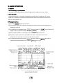
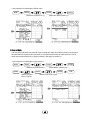
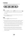
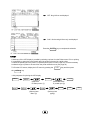
1
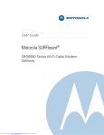
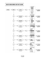
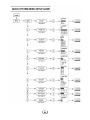
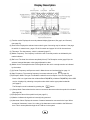
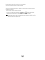
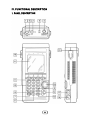
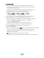
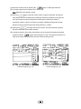
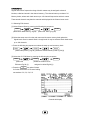
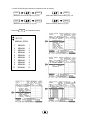
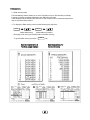
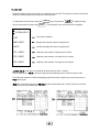
ⅰ
ⅰ
ⅱ
ⅱ
ⅲ
ⅲ
(1) Function mode: Displays the currently selected display (Spectrum, Bar graph, and Counter)
(see page 23)
(2) Scan mode: Displays the selected scan mode.3 types of scanning may be selected. See page
14 and 26 for manual scan, pages 17& 26 for search and pages 16 & 26 for channel scan.
(3) Title name: The data memory, which is, selected (page 37)
(4) Marker Frequency: The frequency in which the unit is currently tuned to as indicated by the
marker indicator.
(5) Ref.Level: The base line reference amplitude(0 level). The Reception modes (page 50)or the
selected external Attenuator value (page 46)sets this value.
(6) Marker Level: The amplitude value of the signal level the unit is currently tuned to as indicated
by the marker.
(7),(8) Center Frequency and Span are used in Manual scan and are described on page 14.
(9) Step Frequency: The scanning frequency increment value set by the
F2
.(page 49)
(10) Reception Mode: The type of modulation needed for aural reception of the incoming signal.
Note: a CW or a signal other than a Narrow Band FM(NBFM), wideband FM(WBFM), AM or SSB
may be displayed by selecting a reception mode which has the appropriate bandwidth
(see page 5).
The Reception mode is selected by pressing the
F3
button.
(11) Sweep Mode: Determines how the scan moves across the screen when the squelch is activated.
(See page 26)
(12) Displays the value of the squelch level (see page 51).
(13) Marker: Indicates the signal level currently being scanned
(14) Attenuator Value: Displays the amount of external attenuation connected to the input. When
an external Attenuator is used, the value of the Attenuator must be added to the Reference
level. This is accomplished through the ATT dB set in the system
ⅳ
ⅳ
CONTENTS
Quick Main Menu set up guide …..……………………………………………………… ⅰ
Quick System Menu set up guide……………………………………………………..…. ⅱ
Function Key Menu guide ..………………………………………………………………. ⅲ
Display Description ………………………………………………………………………… ⅳ
Ⅰ. Introduction ……………………………………………………………..……………… . 4
1. General …………………………………………………………………..……………. . 4
2. Features …………………………………………………………………..…………….. 4
Ⅱ. Specifications ………………………………………………………………..………….. 4
Ⅲ. Precautions ……………………………………………………………………..………… 7
Ⅳ. Functional Description ……………………………………………………….………… 9
1. Panel Description …………………………………………………………….………… 9
Ⅴ. Basic operation ………………………………………………………………….…….. 12
1. General …………………………………………………………………………………. 12
1 Prior to connecting to a power source …………………………………………….. 12
2 Input connection …………………………………………………………………..… 12
3 Powering the unit on ………………………………………………………………… 12
4 Entering a Frequency value …………………………………………………………. 13
5 Scanning ………….…………………………………………………………………. 13
6 Positioning the Frequency marker …………………………………………………. 14
7 Power Off …………………………………………………………………………….. 14
2. Manual Scan ………………………………………………………………………….. 14
3. Ch. Memory Scan ……………………………………………………………………… 16
11
4. Search Scan
………………………………………………………………………… 17
…………………………………………………………………… 19
5. Difference Mode
………………………………………………………………… 19
6. Frequency Counter
7. Recorder Mode
8. Power supply
……………………………………………………………………… 21
………………………………………………………………………… 22
1 Car and AC adapter
……………………………………………………………… 22
2 Battery Replacement
……………………………………………………………… 22
Ⅵ. Menu Description
………………………………………………………………………… 23
1. The Main Menu
……………………………………………………………………… 23
………………………………………………………………… 23
1 Main menu display
…………………………………………………………………… 23
2 Function Modes
3 Scan Modes
………………………………………………………………………… 26
4 Sweep Mode
………………………………………………………………………… 27
5 Edit Channel
………………………………………………………………………… 28
……………………………………………………… 28
5-1 Selecting Edit Channel
……………………………………………… 30
5-2 Assigning a Channel number
5-3 Entering a Channel name
…………………………………………………… 30
5-4 Insert Function
………………………………………………………………… 32
5-5 Delete Function
………………………………………………………………… 32
1-6 Setup Memory
……………………………………………………………………… 32
…………………………………………………………………… 32
6-1 Setup Memory
6-2 Save and Load setups
…………………………………………………………… 34
6-3 Title Names
………………………………………………………………………… 35
1-7 Data Memory
………………………………………………………………………… 37
7-1 Data Memory Setup
……………………………………………………………… 37
7-2 Saving and Loading
……………………………………………………………… 38
7-3 Title name
……………………………………………………………………… 38
22
8 SSB BFO
……………………………………………………………………………….. 39
9 Hold Mode
……………………………………………………………………………… 39
10 Level Hold
…………………………………………………………………………….. 41
2. The System Menu
………………………………………………………………………… 42
1 System Menu display
2 db Unit
………………………………………………………………… 42
………………………………………………………………………………….. 43
3 Power Off
………………………………………………………………………………. 43
4 I/O Menu
……………………………………………………………………………….. 44
5 Printer Menu
6 Copy Set Mode
……………………………………………………………………………. 44
………………………………………………………………………… 45
………………………………………………………………… 46
7 External Attenuators
……………………………………………………………………… 47
8 Test Set Menu
9 SCRB Menu
10 Battery Check
………………………………………………………………………… 47
………………………………………………………………………. 48
11 Keyboard Buzzer ………………………………………………………………………… 48
3. Function Keys……………………………………………………………………………….. 49
1 RUN
2 STEP
3 MODE
…………………………………………………………………………………. 49
…………………………………………………………………………………… 49
…………………………………………………………………………………. 50
4 SQL (Squelch Level)
…………………………………………………………………. 51
…u…………………………………………………………………………………… 51
4. LCD Men
1 LCD Contrast
2 LIGHT
……………………………………………………………………… 51
…………………………………………………………………………………… 52
3 GRID ……………………………………………………………………………………… 52
4 PRINT……………………………………………………………………………………… 53
33
I. INTRODUCTION
1. General
The 3201 is the world’s first hand-held RF Field Strength Analyzer.
With a wide band reception range of 100 KHz to 2060MHz, the 3201 is a compact and
Lightweight portable analyzer. It is the ideal tool for field RF technicians to test, install and
Maintain Mobile Telecommunications Systems, Cellular and Cordless Phones, CB Radios,
Paging Systems, Cable and Satellite TV systems as well as antenna site measurements and
Maintenance.
2. Features
• 100KHz to 2060MHz measurement range
• Measures and demodulates Narrow Band FM(N-FM), Wide Banc FM(W-FM),
AM, Single Side Band (SSB) signals.
• Built-in 2GHz Frequency Counter.
• PLL tuning system for precise frequency tuning.
• Up to 160 channels may be scanned and displayed on the LCD
• Built-in Speaker
• 192 X 192 pixel backlit LCD
• All functions are menu selectable
• Has a RS-232 and parallel interface
II. SPECIFICATIONS
Reception Frequency
Frequency range
: 100KHz to 2060MHz
Freq. Accuracy (TXO)
: ±3PPM
Freq. Accuracy (display)
: ±25PPM
Demodulation
: N-FM, W-FM, AM, SSB
Step frequency
: 5KHz to 9995KHz in multiples of 5KHz and 6.25KHz
Data memory
: Stores 10 displays of up to 160 Channels per display(1600)
Set Up memory
: Stores 10 setups for each scan mode
Reception sensitivity
: Approx.0 –6 dBµ EMF.
(S/N: 12dB at N-FM, 10dB at W-FM)
Scan speed
: 12.5Ch./sec.max.
44
Input impedance
Max.Input voltage
Audio output
: 50Ω (standard)
: Max. 5V RMS
: 120mW into 8Ω speaker
Level Measurement
N-FM mode
Range
: -70 to –20dBmV(-10 to 40dBµV)for 300 to 1800MHz
-60 to –20dBmV(0 to 40dBµV)for 1 to 300MHz and 1800 to 2000MHz
Resolution
: ±0.5dBµV
Accuracy
: ±3dB(at an ambient of temperature of 23℃±3℃)
Repeatability
: ±2dB
Bandwidth
: Approx. 12.5KHz(-6dB)
W-FM/AM/SSB Range
: -60 to –10dBmV(0 to 50dBµV)for 300 to 1800MHz
-50 to –10dBmV(10 to 50dBµV)for 10 to 300MHz and 1800 to 2000MHz
Resolution
: ±0.5dBµV
Accuracy
: ±3dB(at an ambient of temperature of 23℃ ± 3℃)
Repeatability
Bandwidth
: ±2dB
: WFM: Approx. 180KHz(-6dB), AM/SSB:Approx.2.4KHz(-6dB)
Spurious and Noise Level internally generated
: -35dBc W-FM
: -45dBc for N-FM typical, below a full scale signal level frequency.
Functions
Display modes
: Spectrum display
Multi Bar graph display(5, 10, 20, 40, 80, 160CH)
Single Bar graph display
Difference frequency display
Frequency measurement level display
Sweep modes
: Single, Normal, Free Run, Free Single
Scan modes
: Manual, CH.Memory and Search scan
Hold modes
: Delay run, Delay hold and delay stop
Level hold modes
: Max. Hold, Hold, 40mS, 100mS and 200ms peak hold
Squelch function
: Squelch level is displayed as a bar graph and a digital Readout. The
squelch level may be adjusted to any value from the reference level to
Full scale
Copy function
: The copy set mode allows the contents of the Channel edit, Setup and
Data memories to be copied to an external device. Data may also be
written in to these memories from an external device.
55
Frequency Counter
Frequency range
: 9MHz to 2060MHz
No. of digits
: 7 digits
Resolution
: 1KHz
Accuracy
:±50 PPM ±1 count
Sampling time
: 0.512sec.
Input sensitivity
: 9MHz to 2000MHz: 150mV RMS
20MHz to 1000MHz: 100mV RMS
Input impedance
: 50Ω
Max.Input voltage
: 5V RMS Max.
Data memory
: 10 readings may be stored
Miscellaeous Specifications
LCD
: 192 X 192 pixels green, Led backlit
Back light
: Back light will shut off 5 seconds after the last key depression or
continuously on may be selected
RS-232C Interface
: 1200, 2400, 4800, 9600 BPS(8 Pin Mini Din)
Power source
: (6)1.5V AA type NICD batteries 11V to 16V 400mA Max.AC to DC adapter,
12VDC car adapter
Auto Power Off
: Unit will shut off after 5, 10, 20 or 30 minutes of idle time, menu selectable.
Physical specifications
Operating Temperature & Humidity
: 0℃ to 40℃ at 35-85% RH
Storage Temperature
: 10℃ to 50℃
Dimension
: 4”(W) x 9”(H) x 1.77”(D)
Weight
: Approx. 1.4Ib(including antenna)
Std Accessories
Coaxial cable, earphones, Antenna (receiver only), (6)AA NiCd batteries RS232C cable, carrying
Case carrying strap, Vehicle power adapter, AC/DC adapter, operators manual
Optional accessories
: Parallel printer cable and PR-232C mini printer
66
III. PRECAUTIONS
Storage
Do not store this equipment in:
• Direct sunshine, near heating devices or in an automobile in the summer time.
• Locations with high humidity and poor ventilation.
• Dusty or smoky environments.
• Extremely low temperature.
Handling
• This product is a sophisticated electronic device, do not:
Service or perform adjustments.
• Do not apply great force to the keys and switches.
Be sure the slide switch inside the battery cover is set to the right Position, If alkaline
batteries are used set the switch to right (dry position). If NiCd batteries are being used set
the switch to the left (NiCd position)
Warning: If the switch is in the NiCd position when alkaline batteries are used may cause
these batteries to over heat, explore or leak.
Antenna
Due to the broad applications of this unit, the supplied antenna is for the 800MHz cellular band.
It may be necessary to use a different antenna more appropriate for your application.
The receiving conditions vary with location and antenna. On some occasions, it’s not possible to
receive the desired signals due to strong Interference from other electronic sources such as
broadcast stations.
Connecting to other devices
When connecting this unit to other devices (CATV cable etc) be sure that the measured
system voltage is not greater than the maximum input voltage. Use attenuators to prevent
the input voltage from being overloaded by higher than the rated input voltage(5V rms).
If the input voltage is greater than the rated input voltage of this unit, possible damage may
result.
77
Be sure that the external DC input jack is the correct polarity.
The DC jack tip must be positive in respect to ground.
If the unit is not functioning correctly or “locked up” when the power is turned on perform
the following procedure:
• Press the power button to shut the power off
• Turn the unit on again while pressing the
CLR/.
and
ENTER
keys simultaneously.
This will clear the internal memory and return the unit to normal operation.
Note: An alternate method to clear a malfunctioning unit is to select ALL RESET from Test
set menu located in the system menu.
88
IV. FUNCTIONAL DESCRIPTION
1. PANEL DESCRIPTION
99
1). Signal level input connector
Connect to the Antenna or Coax cable. Maximum input Voltage is 5 Volts.
2). Frequency counter input
Connect to the signal source to be measured. Maximum input voltage is 5 Volts.
3). Volume control
Audio output Volume control. To increase the volume, rotate the Volume control clockwise.
4). Earphone Jack
5). Attenuator
“ “ (Pushed in) Inserts 10dB of attenuation into the Signal level input. Used in the presence
of noise or very strong signals.
“ “ (Pushed Out) No attenuation
6). LCD (Liquid Crystal Display)
Displays the Signal levels, their characteristics (frequency, amplitude, etc) and pertinent system
data.
7).
POWER
Press this button to turn the power on. Press again to turn the power off.
8).
LCD
KEY
Press the
LCD
key to display the LCD menu. The LCD menu items consists of LCD
Contrast control, LCD Grid select, Backlight and Print command. These items are
displayed when the
9).
LCD
key is pressed and selected with the
F1
-
F4
keys.
MENU
Pressing the
MENU
key once displays the Main Menu items. Pressing the
again displays the System Menu items and pressing the
LCD to the signal level displays.
10
10
MENU
MENU
key
key a 3rd time returns the
10).
ENTER
This key enters the menu item you have selected or the numeric values you have entered
form the keyboard.
11).
F1
to
F4
These keys select: Run, Step frequency menu, Reception mode menu, and squelch Level.
These keys are located at the bottom of the LCD display. They also are used to select the items
in the LCD menu when the
12).
0
to
9
LCD
key is pressed.
Numeric keys
Enters numeric data from the keypad for frequency values. The
are also used for assigning a sign to a numeric Value. The
(-) value used for difference mode only), the
13).
0
and
0
1
1
keys
key will enter a negative
key a positive (+) value.
CLR/.
This key is used for entering decimal points. If a decimal point is already entered, this key is
then used for clearing a keyboard entry.
14).
This key is used for incrementing and decrementing the Market frequency and for selecting
items in the various menus.
15). Rotary Dial Knob
Performs the same function as the up/down key (
) but at a faster rate.
The rotary dial knob allows one-handed operation.
16). DC Input Jack
The AC/DC adapter and cigarette lighter adapter connect to this input for applying DC
Power to the unit from an external source.
17). RS-232C Connector(8 pin mini DIN connector)
This connector is used for interfacing to a personal computer or a printer.
18). Belt Clip
For attaching the RF-3201 to your belt.
19). Speaker
For listening to the demodulated output of a RF carrier signal level.
11
11
V. BASIC OPERATION
1. General
1 Prior connecting to a power source
See page 22 for inserting batteries, battery charging and connecting to a power source.
2 Input connection
Connect the antenna or coax cable to the BNC input marked ANT if measuring a RF carrier
signal level. If measuring a frequency connect the coax cable to the Frequency counter input.
Note: Do not exceed 5V rms
3 Powering the unit on
[1] Press the
POWER
key to turn the unit on.
[2] The welcome screen will be displayed followed by the last screen that was displayed prior to
shutting the power off.
[3] To adjust the LCD contrast press the
key then press the
LCD
display is set to the desired contrast then press
ENTER
keys until the LCD
.
[4] See the graphic below for a description of the LCD display when powered on.
[5] Adjust the volume control for an appropriate sound level. If the signal level is below
the squelch level there will be no output sound from the speaker.
[6] To adjust the squelch level press the
key then press the
F4
squelch level is at the desired level. Press the
12
12
ENTER
key to quit.
keys until the
4 To enter a frequency value
[1] The selected scan mode is displayed in the top center of the LCD. In the above,
example manual scan was selected. The frequency entered from the keyboard in this
case is the is the center frequency and is the frequency indicated by the market.
Note: in order to enter a frequency from the keyboard scanning must be halted.
(The
RUN
icon on the bottom left of the LCD should not be highlighted.)
[2] A frequency maybe entered from the keyboard by pressing the
and the
0
to
9
keys
key.
CLR/.
Example1: To enter 100.00625MHz from the keyboard: Press the following key sequence:
1
0
0
CLR/.
0
0
6
2
5
ENTER
Example2: To enter 500KHz press the following key sequence:
0
Note: The
CLR/.
CLR/.
5
ENTER
Key is used for entering the decimal point but if the decimal point has
already been entered, pressing the
CLR/.
Key will clear the entered frequency value.
[3] The frequency value has different functions for the Manual, Search and Cannel scan.
The entered frequency in manual scan sets the Center frequency where as the entered
frequency values in search scanning sets the Start and stop frequencies.
In the Channel scan mode the entered frequency value is stored along with its channel
name in the Channel memory (see page 28 through 30). This will be used for scanning
previously stored scans along with their channel names and frequency.
5 Scanning
[1] Pressing the
F1
key highlights the
RUN
icon and the scanning will start.
[2] If Free Run sweep is selected from the Sweep menu scanning will be continuous and
regardless of the squelch level. Pressing the
13
13
F1
key a second time will stop the scanning.
[3] When Normal Sweep has been selected the scan will halt when the signal level value is
greater than the squelch level. Scanning will resume when the signal level value drops
below the squelch level.
[4] When scanning is halted the marker will indicate the signal level and display the
amplitude value on the LCD.
6 Positioning the Frequency Marker indicator
Pressing the
keys or rotating the dial knob
when the scanning has been halted can be used to
position the marker frequency indicator over a
signal level in order to find it’s frequency and
signal level amplitude values.
7 Power Off
Press the
POWER
key to turn the unit off when
finished.
Note: When the unit is powered-on again, the
screen prior to powering off will be displayed.
2. Manual Scan Mode
[1] when Manual scan mode is selected, It is necessary to enter the following information:
a) The Center frequency value from the keyboard,
b) The type of carrier signal modulation from the
MODE
menu.
c) The Frequency Span which is set by the Step frequency. The Frequency span is
determined by the number of channels per displayed (Selected from the function menu
multiplied by the step frequency. See the 2 examples below on how the frequency span
is determined by the step frequency.
Example 1: To set a frequency span of 8MHz using the Spectrum display mode a step
frequency of 50KHz is required(160 x 0.050MHz = 8MHz).
Example 2: If a 40 Bar graph display is selected and the step frequency is 100KHz the
Frequency span is 40 x 0.1MHz = 4MHz.
14
14
[2] To select the Manual scanning mode press the following key sequence:
MENU
ENTER
ENTER
(Select the Scan menu) (Select Manual Scan mode)
[3] The center frequency, Span, Step Frequency and reception mode are displayed in the lower
part of the LCD.
Note: The frequency span is not displayed in the 2 channel difference, Single or counter modes.
[4] To enter the Center/Market frequency the unit must not be Scanning (Run icon not highlighted)
(See pages 12 and 13)
[5] When the scanning is stopped the Market frequency indicator may be positioned over a
signal level of interest by pressing the
keys or rotating the dial knob.
The position of the market may be moved by up to 160 channels.
(+80 channels to –80 channels)
[6] Pressing the
F1
key will highlight the RUN icon and scanning will start from left to right.
In the 2-channel mode the market/center frequency and the difference frequency are scanned
and displayed.
Note: Scanning is not available in the signal channel or counter mode.
[7] You can save 10 displays of up to 160 channels and their setups by storing them in the Data
and setup memory. These may be selected from the main menu.
(see pages 32 through 38)
[8] Example of a manual scan display
15
15
3. Ch. Memory Scan
[1] Names and frequencies of signal levels of interest may be entered and stored in the
channel memory prior to scanning. When scanned these signal levels will be displayed
along with their frequencies and name.
Ten displays of up to 160 signal level Channels per display(1600 channels total) may be
entered, edited and stored in the channel memory (See pages 28 through 30)
[2] To select the Channel scan mode press the following key sequence.
MENU
ENTER
(Select Scan Mode)
ENTER
(Select Chan. Scan)
[3] The LCD will display the current signal level frequency as indicated by the marker, the
signal amplitude, and the channel name displayed at the bottom of the LCD.
[4] A signal level frequency may also be entered in to the channel memory from the keyboard
by pressing the
0
to
9
keyboard keys and the
CLR/.
(see page 12 for entering frequencies).
The type of reception (demodulation) must also be selected (see page 48).
The step frequency will be indicated but is not used for the Channel scan mode.
[5] Pressing the
F1
key will start the scan from the left most position
(The RUN icon is highlighted).
[6] When scanning is halted, pressing the
keys or rotating the dial knob will move the Marker
frequency indicator and display the amplitude, frequency and name of the signal levels
displayed on the LCD. The market indicator may be moved up to +80 channels to –80
channels from its present position.
Note: Scanning is inoperative in the Single scan and counter modes.
In the Difference mode only the Market and the difference frequency is scanned and displayed.
16
16
[7] A stored display in the Data memory may be scanned and displayed in the channel scan
mode. The set up memory in this case is used for selecting the stored display to be scanned.
[8] Example of a channel scan display:
4. Search Scan
[1] Search scan is the scanning between a start stop frequency, which are entered from the
keyboard.
[2] To selected the scan mode enter the following key sequence:
MENU
(Select the Scan menu)
ENTER
ENTER
(Select search Scan)
[3] The START, STOP, STEP frequencies and the reception mode (demodulation type) will
be displayed at the bottom of the LCD with the start frequency highlighted.
[4] Enter the START FREQUENCY from the keyboard. This frequency will now be displayed
as the start frequency and at the market frequency indicator (See page 12).
When the START frequency is entered, STOP FREQUENCY will be highlighted.
Enter the STOP frequency from the keyboard.
Note ; scanning must be stopped before entering the START and STOP frequencies.
17
17
[5] Pressing the
or rotating the rotary dial while the scanning is stopped will move the market
frequency indicator at the step frequency increment to different positions depending on which
key is pressed or which direction the rotary dial is rotated.
[6] Press the
key to start the scanning. The scanning will start at the start frequency the
F1
Marker frequency indicator will update at the step frequency increment until it reaches the
STOP frequency. When the stop frequency is reached the scanning will start over at the
start frequency if Free Run or Normal sweep was selected or stop if Free single or single
sweep was selected.
[7] Pressing the
F1
key again will halt the scanning. The frequency and amplitude of the
signal where the Marker frequency indicator halted will be displayed.
[8] If the Scan mode is changed to Manual Scan the frequency where the marker halted
(in step 7) will become the center frequency.
[9] You can save 10 displays of up to 160 channels per display and their setups by storing them
in the Data and setup memory in the main menu. (See pages 32 through 38)
18
18
5. Difference mode
Scans and displays 2 signal levels in which one signal level frequency is entered from the
Keyboard and the other signal level is at a difference frequency selected from the step
Frequency menu. The amplitude of each is displayed as a bar graph on the right side of the
Display along with their signal difference.
This feature is useful for measuring the difference in amplitudes between the video carrier
And audio carriers of a TV signal or measuring the variation in amplitude of a transmitted
Signal at different locations
[1] To select the 2 channel difference mode press the following key sequence:
MENU
ENTER
(Select the Function mode)
ENTER
(Select 2 channel Difference)
[2] Enter the marker frequency to be measured from keyboard.
[3] Select or enter from the keyboard the difference frequency to be measured form the step
frequency menu (press the
key)
F2
[4] The LCD will display the bar graphs of the marker frequency and difference frequency
amplitudes. The difference amplitude between the two signal levels will also be displayed.
[5] Press the
keys to select the marker or difference frequency
6. Frequency Counter
The frequency counter may be used to measure and record unknown frequencies
[1] To select the frequency counter press the following key sequence
MENU
ENTER
(select Function)
ENTER
(select counter)
19
19
[2] Select the counter mode by pressing the
keys or rotating the dial knob.
[3] Connect the signal source output to the counter input
Note: Maximum input voltage is 5Volts
[4] Press the
key to start the counter. When a signal is measured, is frequency
F1
value will be stored in the data memory starting at frequency position #1 (see page 38).
If the input frequency values changes the new frequency value will be stored in
successive positions until all 10 positions are written. Additional frequencies will then
displace previously stored frequencies starting with the 1 position.
[5] Pressing the
F1
key again will stop the counter. The last measured frequency
will be the displayed at the marker indicator
[6] A frequency stored in the counter data memory may be recalled by selecting the desired
frequency with the
keys and pressing the F4 key. This frequency may then be
used as the center frequency when set to the manual-scanning mode.
Difference Display (Pg. 19)
Counter Display (Pg. 19)
20
20
7. Recorder function
The 3201 may be used to display and record (store in memory) trends and variations of a
Signal level as a continuous pattern of bar graphs. This feature is convent if the amplitude
Variations of a signal level under test need to be monitored over a period of time.
To set the Recorder mode use the following procedure:
[1]
MENU
ENTER
(Select the Scan menu)
[2]
MENU
ENTER
(select Manual or search scan)
ENTER
ENTER
(Select the function menu) (Select spectrum or bar graph display)
[3] Input from the keyboard the frequency to be measured. If using the Manual scan mode set
the center frequency of if using the search scan input the start frequency.
[4] Set the step frequency to 0㎑. This may be accomplished as follows:
Select the step frequency menu by pressing the
F2
key.
Then press the following key sequence:
0
CLR/.
[5] Start the scan by pressing the
0
F1
ENTER
key.
The scan will start from the left side of the LCD at a rate of 80mS/CH or 12.5Ch/Sec.
This is 3.2sec/Div. In the 80Bar graph display the scan
speed is 6.4Channels per second or 1.6 sec per division.
[6] The displays and settings may be stored in the data and setup memories
21
21
8. Power supply
1. Car adapter and Ac adapter
[1] Before connecting be sure the power is off
[2] Connect the AC adapter to the external DC input jack (see page 9 for location)
2. Battery replacement
[1] Shut of the power and remove the external power adapter.
[2] Remove the screws form the battery cover. Lift the battery cover and remove the 6 AA
batteries.
[3] Set the slide switch according to the type of battery being installed. (To the left for
alkaline or manganese batteries (dry). To the fight for NiCd batteries)
[4] Insert the new batteries into the case. Observe battery polarity.
[5] Replace the battery cover and reinstall the screw.
[6] Check to the Battery test indicator in system menu (see page 48) for the condition
of the battery installed.
[7] For a quick charge it is recommend charging the batteries while the power is off.
When using the car adapter recharge the batteries while the engine is operating
22
22
Ⅵ. Menu Description
1. The Main Menu
Press the
MENU
Press the
The
ENTER
key to display the Main menu as shown below.
key or rotate the rotary dial to highlight the desired menu item then press
key to make the selection.
1. Main menu display
☞ To display the main menu Press the following keys
POWER
MENU
ENTER
(select the desired menu)
Main Menu Display
2. Function mode
The Function mode selects the type of LCD display.
☞ Press the following keys to select the Function mode:
MENU
(select the Function mode)
ENTER
ENTER
(select the desired display)
23
23
▲▼
▲▼
FUNCTION (Display)
① SPECTRUM
① SPECTRUM
▶ Scans 160 Channels and displays their signal levels as a spectrum. The
channel at the marker indicator will have its frequency and amplitude
displayed on the LCD. See figure 1 on page 25.
② BAR 160CH
② BAR 160CH
▶ Scans 160 Channels and displays their signal levels as bar graphs. The
channel at the marker indicator will have its frequency and amplitude
displayed on the LCD. See figure 2 on page 25.
③ BAR 80CH
③ BAR 80CH
▶ Scans 80 Channels and displays their signal levels as bar graphs. The
channel at the marker indicator will have its amplitude and frequency
displayed on the LCD. See figure 3 on page 25.
④ BAR 40CH
④ BAR 40CH
▶ Scans 40 Channels and displays their signal levels as bar graphs. The
channel at the marker indicator will have its amplitude and frequency
displayed on the LCD. See figure 4 on page 25.
⑤ BAR 20CH
⑤ BAR 20CH
▶ Scans 20 Channels and displays their signal levels as bar graphs. The
channel at the marker indicator will have its amplitude and frequency
displayed on the LCD. See figure 5 on page 25.
⑥ BAR 10CH
⑥ BAR 10CH
▶ Scans 10 Channels and displays their signal levels as bar graphs. The
channel at the marker indicator will have its amplitude and frequency
displayed on the LCD. See figure 6 on page 25.
⑦ BAR 5CH
⑦ BAR 5CH
▶ Scans 5 Channels and displays their signal levels as bar graphs. The
channel at the marker indicator will have its amplitude and frequency
displayed on the LCD. See figure 7 on page 25.
⑧ DIFFEREN
⑧ DIFFEREN
▶ Scans and displays 2 signal levels in which one frequency is entered
from the keyboard and the other signal level is at difference frequency
selected from the step frequency menu. The amplitude of each is
displayed as a bar graph along with their difference amplitude. See
Figure 8 on page 25.
⑨ SINGLE
⑨ SINGLE
▶ Displays a single frequency and its amplitude as a bar graph. See figure 9
on page 25.
⑩ COUNTER
⑩ COUNTER
▶ Displays a measured frequency together with its amplitude as a bar graph
see figure 10 on page 25.
24
24
25
25
3. Scan modes
Selects the manner in which signal levels are scanned and displayed on the LCD.
There are three scan modes to choose from, Search, Manual and Channel scan.
☞ Press the following key sequence to display the scan mode menu:
MENU
(select the Scan menu)
ENTER
ENTER
(select the desired scan mode) See below
▶ Manual Scan: (Menu Scan)
A signal level frequency is entered from the keyboard
And is displayed as the center frequency.
The frequency span is set by a frequency selected form
The step frequency Menu.
▶ Channel Scan: (CH Scan)
Names and frequencies of signal levels of interest may
Be entered and stored in the channel memory prior to
Scanning. When scanned these signal levels will be
Displayed along with their frequencies and name.
▶ Search Scan: (search)
Scans and displays signal levels between a start and
Stop frequency. The start and stop frequencies are
Entered from the keyboard and are displayed on the
LCD
26
26
4. Sweep mode
☞ Press the following keys to select the sweep mode menu
MENU
ENTER
(select scan Sweep Mode menu)
ENTER
(Choose the desired sweep mode)
▶ FREE RUN (Free Sing)
The display trace sweeps continuously across the screen
Regardless of the signal level amplitude or squelch level
setting
▶ FREE FUN SINGLE:
The trace will sweep across the screen regardless of the
Signal amplitude or squelch level setting and halt at the
End of the screen. Pressing the
RUN
button will then
Restart the trace from the beginning.
▶ NORMAL
The display trace will sweep across the screen until
Incoming signal amplitude is greater than the squelch
Level. The trace will halt at this point and can be restarted
By pressing the up
Item in the
HOLD
key or automatically if a hold
menu is selected.
▶ SINGLE
Operates the same as normal sweep except the sweep
Will stop when the trace reaches the end the screen.
The trace may I be restarted from the beginning by
Pressing the
27
27
RUN
button.
5. Edit Channel
Signals with known frequencies along with their manes may be assigned a channel
Number, edited and stored in the channel memory, The channel memory consists of 10
Memory banks, where each bank stores up to 160 channel frequencies and their names
These stored channels may then be scanned and displayed in the Channel scan mode.
5-1 Selecting Edit channel:
[1] Select Channel Scan by pressing the following key sequence
MENU
ENTER
(Select Scan Mode menu ① Pg.29)
ENTER
(Select CH. Scan ② Pg.29)
[2] Select the setup menu from the main menu and choose a memory bank where the
Signal levels are to be stored. Bank 1 though band 10 may be selected. Each bank stores
up to 160 channels.
☞ Press the following key sequence to select the setup up and a memory bank.
MENU
ENTER
ENTER
(Select setup menu ③ Pg.29) (Select the desired memory bank Pg.29 ④)
[3] Select the CH. Edit Menu by pressing the following key sequence
MENU
ENTER
(Select CH
(Select the Channel to be
Edit menu Pg.29 ⑤)
☞ Press the
F4
ENTER
assigned or edited Pg.29 ⑥)
key when finished.
for further information on Channel editing
see sections 5-2, 5-3, 5-4, 5-5.
Channel edit display
28
28
Examples of the channel edit screen.
EDIT
EDIT CH
CH MEMO
MEMO
Mem.
Mem. NO.
NO.
11
22
33
44
55
66
77
88
99
10
10
NAME
NAME
WLTW
WLTW
WWOR
WWOR
WPIX
WPIX
WABC
WABC
WPLJ
WPLJ
WCBS
WCBS
WPBS
WPBS
WRCA
WRCA
WQXR
WQXR
BILL’S
BILL’S TAXI
TAXI
29
29
FREQ
FREQ
107.6
107.6 MHz
MHz
191.75
191.75 MHz
MHz
203.75
203.75 MHz
MHz
179.75
179.75 MHz
MHz
95.5
95.5 MHz
MHz
101.1
101.1 MHz
MHz
215.75
215.75 MHz
MHz
71.75
71.75 MHz
MHz
104.3
104.3 MHz
MHz
153.2523
153.2523 MHz
MHz
5-2 Assigning a channel number
[1] To assign a signal level, a channel number, or edit a frequency in the Channel Memory
(refer to screen in the example in section 5-1), select the desired channel to be assigned or
edited by pressing the
[2] Highlight the
F1
Key or rotating the rotary knob.
icon in the lower left-hand side of the LCD screen by pressing the
NAME
key.
[3] To enter a frequency of 100.02625 MHz in to the Channel memory:
Press the following Key sequence:
1
0
0
2
6
CLR/.
0
5
2
ENTER
The entered frequency will be displayed to the right of the Marker arrow (MKR
) located
in the center of the LCD when the ENTER key is pressed.
[4] When
0
CLR/.
ENTER
is entered as a frequency, this channel will
skipped when scanned.
Note: The
CLR/.
Key when pressed, will enter a decimal point after numerical sequence has
been entered from the keyboard. If a frequency has already been entered (including the decimal
point), pressing this key will clear the frequency display.
5-3 Entering a name in to the Channel Memory
[1] To assign a signal level, a channel name or edit a Channel name in the Channel Memory
(refer to the example shown in section 51), select the channel to be named or edited by
pressing the
[2] Press the
Key or rotating the Dial Knob.
F1
Key to highlight the
NAME
icon located on the bottom left of the screen.
The alphanumeric character entry cursor will then appear at the bottom of the LCD screen as a
reversed contrast block.
Note: Be sure the Character entry cursor is in the left most position before entering a channel
name. To move the character entry cursor press and release the
is in the left most position.
30
30
F1
key until the cursor
[3] To select Alphanumeric characters for a channel name press the
key of rotate the
rotary dial Knob until the desired character is displayed.
Press the
F1
key to advance the cursor to the next character position and repeat the
procedure until all characters are entered.
Note: Numeric characters from
[4] Pressing the
ENTER
0
to
9
may also be entered from the keypad.
key will store the channel name into memory as shown in the
figure in section 5-1.
[5] Example: To enter the Channel name NHK: 1 in to the channel memory use the
following procedure: (See the below figure.)
[1] Press the
F1
key to highlight the
NAME
icon. Press the
key or rotate
the dial knob until the letter of ‘N’ appears in the reversed contrast cursor block.
[2] Press the
F1
key to enter the second character. Press the
key or rotate
the dial knob until the letter of ‘H’ appears in the reversed contrast cursor block.
[3] Enter the remaining of the characters in the channel using steps 1 and 2
[4] Press the
CLR/.
key after the last character in the Channel name to store the name in
memory.
Note: When the
CLR/.
Key is pressed a space will be entered as a character and the cursor
Will advance to the next position to the right.
31
31
5-4 Insert (INS) function.
The insert function allows you to add a new channel name and frequency into any position in
your stored Channel list.
[1] Highlight the where the new channel is to be inserted in to the Channel list by pressing
the
[2] Press the
keys or rotating the dial knob
F2
key to highlight
INS
at the bottom of the LCD screen.
[3] Assign a frequency and name to the new channel using the procedure given in sections
5-2 and 5-3.
[4] Press the
ENTER key to insert the new Channel in to the desired channel list location.
5-5 DEL (Delete) function
[1] Select the channel to be deleted by pressing the
[2] Press the
F3
keys or by rotating the dial knob
key to delete the channel
6 Setup memory
6-1 Setup Menu
[1] The Setup memory menu enables you to save previously selected menu settings and recall
them at a later date. This provides fast display setups when time is of the essence.
[2] The menu settings for the LCD display screens in the Channel, Manual and search scan
modes may be stored in the setup memory.
Note: The setup memory in the channel scan mode is used for selecting one of the 10 channel
list which stores 10 displays of 160 Channel frequencies and their names. This allows 1600
channels to be saved in 10 channel scan displays.
32
32
☞ Press the following key sequence to select the set up memory:
MENU
ENTER
(Select the Scan mode menu ① Pg. 33)
MENU
(Select the desired scan mode ② Pg. 33)
ENTER
(Select the set up menu ③ Pg. 33)
Press the
ENTER
F4
ENTER
(Select a memory bank ④ Pg. 33)
to complete the setup
SET
SET UP
UP
MANUAL
MANUAL SCAN
SCAN
11
22
33
44
55
66
77
88
99
10
10
MANUAL
MANUAL
MANUAL
MANUAL
MANUAL
MANUAL
MANUAL
MANUAL
MANUAL
MANUAL
MANUAL
MANUAL
MANUAL
MANUAL
MANUAL
MANUAL
MANUAL
MANUAL
MANUAL
MANUAL
11
22
33
44
55
66
77
88
99
10
10
33
33
6-2 Save and Load Setups
[1] Select the memory location where a setup is to be saved or recalled with the
or rotary dial (See page 32 sect. 6-1)
[2] Press the
F2
key to highlight the
SAVE
icon at the bottom of the LCD.
This will save the current menu selections, display data and the title name in the selected
memory location.
[3] Press the
F3
key to highlight the
LOAD
icon at the bottom of the LCD.
This will recall from the selected memory location the previously stored menu selections,
display data and the title name
[4] Press the
F4
when finished
[5] The following items are saved in the setup memory when the
• Marker frequency
• Reception mode
• Step Frequency
• Difference frequency
• Attenuator level
• Sweep mode
• Function mode
• Max Hold mode
• Squelch level
• Hold mode
• SSB BFO
• SCRB set level
• Start/Stop Frequency
• Title names (10 alphanumeric Characters Max).
34
34
F2
key is pressed.
key
☞ Press the following key sequence to load or recall a setup from memory
a) To recall a setting
Select the memory location (see sect 6.1)
F3
F4
Load ⑤
End
F2
F4
Save
End
b) To save a setting
Select the memory location (see sect 6.1)
6-3 Title name
A title name with up to 10 alphanumeric characters may be assigned to a display setup.
To enter a title name use the following procedure.
[1] Press the
F1
Key to highlight the
NAME
icon located on the bottom left side of the
LCD screen. The alphanumeric character entry cursor will appear at the top middle of
the LCD screen as a reversed contrast block.
[2] The Characters for the title name are selected with the
[3] Press the
F1
Keys or the rotary dial.
key to select the desired character and to advance the character cursor
to the next character position. Numerical characters may be entered with the numeric keys.
Up to 10 alphanumeric characters may be used for a title name.
35
35
[4] When the title name is completed press the
ENTER
key
Example: To enter CATV 9501 as a title name use the following procedure:
A) Press and release the
C
B) Select
key. Until the character cursor is in the first character position.
F1
with the
a) Press the
F1
b) Select the
A
c) Press the
F1
Keys or the rotary dial knob.
key to advance the cursor to the next character position
with the
key
d) Select the remaining letters
e) Press the
key or rotary dial
CLR/.
T
V
,
key to enter a space
f) Press the
9
g) Press the
ENTER
5
,
,
0
,
a) Select the title name to be changed or edited with the
F1
e) Press the
numeric keys
F1
key and using the same
keys or rotary dial.
key to highlight the character in the title name to be changed
c) Press the
d) Press
1
key
[5] A title name may be changed or edited by pressing the
procedure as in sect. 6-1
b) Press the
using the same procedure as a above
key to select the new character
F1
to advance the cursor to the next character ⑥ to be changed.
ENTER
key then the
F4
key when finished
36
36
7 Data memory
7-1 Data memory setup
The Data Memory feature allows you to save 10 displays of up to 160 channels per display
in memory including amplitude, Attenuator and difference level data.
These displays may be recalled at a later time. In the counter mode 10 measured frequencies
may be saved and then recalled.
☞ To display the Data memory menu use the following key sequence:
MENU
ENTER
(Select data memo)
(Select Memory location)
(See page 38 for saving and loading data in the data memory)
To quit the data memory press the
F4
key
Data Memory Menu for all
Functions except counters
Data Memory Menu for
the Counter mode
F4
37
37
7-2 Saving and loading
[1] The current LCD screen data and title maybe saved in a memory location by selecting the
memory location with the
keys and pressing the
Note: In the counter mode, pressing the
(save).
key will store the frequency value indicated
F2
by the marker.
F2
[2] Previously stored data and title name may be recalled from a memory location by selecting
the desired memory location with the
[3] Press the
F4
keys and pressing the
F3
(Load) key.
(End) key when finished.
[4] Frequency measurements in the counter mode may be saved and recalled in the data memory,
when in the Run mode, pressing the
key will continuously store and update the
F1
frequencies displayed at the marker indicator.
7-3 Assigning a title name
☞ To assign a title name to a display stored in the data memory use the following key sequence:
MENU
ENTER
(Select Data
Memo.)
F1
Name
(Select Data
Memo. Location)
F1
(Select Data
(Shift to next
Character ③) Character pos.)
(Select next
Character etc.)
38
38
F3
F4
Load
End
ENTER
F2
F4
Save
End
8 SSB BFO
[1] Press the
MENU
key and highlight the SSB BFO by pressing the
the dial knob then pressing the
ENTER
① or rotating
key. Tuning the BFO will demodulate single side band
signals.
[2] The carrier frequency may be reinserted by tuning the BFO to 1.5KHz above the carrier
frequency to recover the LSB or to 1.5KHz below the carrier frequency to recover the USB
by pressing the
[3] Press
ENTER
② or rotating the dial knob until the audible signal is heard.
when finished
9 Hold Mode
The Hold mode may be activated for use in the NORMAL or Single sweep mode.
In hold mode scanning will be temporarily halted (approximately 5 seconds) when a signal Level
amplitude is greater than the squelch level and then resumes scanning regardless of the signal
level amplitude.
To activate the HOLD mode:
[1] Press
MENU
key and select the Hold mode menu by pressing the
MENU
or rotating
the dial knob
[2] Select the desired hold mode from the menu. The following types of hold may be selected:
39
39
HOLD
HOLD MODE
MODE
OFF
OFF
DELAY
DELAY RUN
RUN
Hold mode disabled. Scanning stops when the signal level amplitude
is greater than the Squelch level and restarts when the signal level
amplitude drops below the Squelch level.
Scanning will stop when received signal level amplitude is greater
than the squelch level and then restart after the hold time
(approximately 5 seconds) if the signal level amplitude remains
greater than the squelch level. If the signal level drops below the
squelch level during the hold period scanning will restart.
DELAY
DELAY HOLD
HOLD
Scanning will stop when a received signal level amplitude is greater
than the squelch level then restart after the hold period, irregardless
of the signal level value during the hold period.
HOLD
HOLD STOP
STOP
Scanning will halt when the signal level is greater than the squelch
level and will remain stopped. Pressing the
key will restart
the scan.
40
40
10 Level Hold
Stores and displays the maximum value of a signal level on the LCD. This feature is useful for finding the
maximum value a signal level reaches over a period of time.
To select the Level Hold menu press the
knob to select level hold and press
MENU
ENTER
key and press the
or rotate the rotary
. The following Level hold options will be displayed.
LEVEL
LEVEL HOLD
HOLD
OFF
OFF
Level hold is disabled
MAX
MAX HOLD
HOLD
Displays the maximum value of a signal level
HOLD
HOLD
Holds and displays the value of a signal level
PK
PK 11 HOLD
HOLD
Holds the peak variation of signal level for 40mS
PK
PK 22 HOLD
HOLD
Holds the peak variation of a signal level for 120mS
PK
PK 33 HOLD
HOLD
Holds the peak variation of a signal level for 200mS
A LEVEL HOLD mode may be operated at all times while the 3201 is running.
Prior to scanning in a HOLD mode set all signal levels amplitudes to their minimum value or 0dB.
The Peak hold modes are useful for displaying signal levels with a long burst or pulse time such as a
PCS carrier signal.
Note: The scanning time during the PK HOLD modes will be longer than 12.5CH. /Sec due to the time
needed to set up and establish the hold time.
41
41
2 THE SYSTEM MENU
The system menu contains the basic system operating and measurement parameters
1 System Menu display
☞ To Display the System menu press the following Key sequence:
MENU
MENU
ENTER
(Select the desired menu)
SYSTEM
SYSTEM
dB
dB UNIT
UNIT
Selects the decibel measurement unit. dB㎶, dBmV or dBmW may be
selected
POWER
POWER OFF
OFF
Sets the amount of time the unit will shut of when if no keyboard entry
is made.
I/O
I/O SET
SET UP
UP
Sets serial Baud rates or parallel port operation
PRINTER
PRINTER
Selects the type of printer that is to be used for printing screen data
COPY
COPY SET
SET
Used for down loading the data memory to an external device
ATT
ATT dB
dB SET
SET
Sets the reference level when external Attenuators are used
TEST
TEST SET
SET
For internal testing and calibration
SCRB
SCRB
Setting the sound modulation
BATT
BATT CHECK
CHECK
Indicates the present battery voltage level
BUZZER
BUZZER
Enables or disables the keyboard entry beeper
42
42
2 Setting the display dB units
☞ To Display the System menu press the following Key sequence:
MENU
MENU
ENTER
(Select dB unit menu)
ENTER
(Select dB㎶, dBmV or dBmW)
3 Setting the Auto power off feature
This feature sets the amount of keyboard idle time before the unit shuts off. 5, 10, 20 or 30
Minutes may be selected.
☞ Key sequence for selecting the Auto power off menu.
MENU
MENU
ENTER
(Select the power off menu ①)
(Select the amount of idle time ②)
POWER
POWER OFF
OFF
AUTO
AUTO OFF
OFF 55
Power will shut off after 5 minutes of idle time
AUTO
AUTO OFF
OFF 10
10
Power will shut off after 10 minutes of idle time
AUTO
AUTO OFF
OFF 20
20
Power will shut off after 20 minutes of idle time
AUTO
AUTO OFF
OFF 30
30
Power will shut off after 30 minutes of idle time
NONE
NONE
Auto-power off is disabled
43
43
ENTER
4 I/O Setup Menu
This Menu enables the serial port with baud rates of 1200, 2400, 4800 or 9600 for connecting
To a computer or serial printer. The parallel port may also be selected for connecting to a parallel
printer.
Note: To connect a parallel printer to the RF-3201, the optional parallel printer cable is needed.
☞ Key sequence for selecting the I/O setup menu
MENU
MENU
ENTER
(Select the I/O Setup menu ①)
ENTER
(Select Baud rate or parallel port ②)
5 Printer Menu
Displays the list of printers, which may be connected to the 3201 for printing out display data.
PRINTER
PRINTER
PRINTY
PRINTY
Selects the optional “Protek Printy” (part No. PR 232)
ESC/P
ESC/P TYPE
TYPE
Selects ESC/P type Epson printers
MN
MN TYPE
TYPE
Selects NM type NEC printers
(Set NM printer to the Copy Mode)
See Page 53 for printer operation
44
44
☞ Key sequence for selecting the Printer menu
MENU
MENU
ENTER
ENTER
(Select the printer menu ①)
(Select the desired printer ②)
6 Copy set Mode
The copy set mode allows the contents of the Channel edit, Setup and Data memories to be copied to
an external device. Data may also be written in to these memories from an external device. The I/O
setup must be performed prior to using this feature. (See page 44 section 4)
☞ Key sequence for selecting the copy set menu
MENU
MENU
(Select the I/O setup menu)
MENU
(Select BPS or parallel port)
ENTER
ENTER
(Select Copy Set
menu ① Pg.45)
ENTER
ENTER
(Select Copy out ② Pg.45)
45
45
CLR/.
7 External Attenuators
An external Attenuator may be connected to the signal level input in order to increase the
measurement range. Upon doing so it is necessary to change the Reference level. This is
accomplished by selecting the appropriate attenuation value in the ATT dB set menu.
Standard Attenuator values of 3,6,10,20,30,40,50 or 60 dB may be selected with the
Keys or dial knob or a non-standard value may be entered through the key board.
The reference level displayed on the LCD will then change according to the dB value selected.
Example: If a 20dB Attenuator is connected to the input. Select 20dB from the ATT dB Set menu. The
reference level displayed on the LCD will change to 20dB.
☞ Key sequence for selecting the ATT dB set menu
MENU
ENTER
MENU
(Select the ATT dB
menu ①)
(Select the Standard
Attenuator value ②)
ATT
ATT dB
dB SET
SET
xx.xxdB
xx.xxdB
A value entered from the key board
0.0
0.0 dB
dB
Standard Attenuator values that may be selected
3.0
3.0 dB
dB
Note: when the Attenuator switch is pressed, (see page 9) 10dB of
attenuation is inserted in to the input. The above procedure should be
performed to change the reference level to 10dB.
60
60 dB
dB
46
46
8 Test set menu
The test set menu contains the following utilities:
TEST
TEST MODE
MODE
OFF
OFF
The signal level value displayed on the LCD includes the Calibration
correction factor. For normal operation this mode should be selected
TEST
TEST 11
The LCD displays the output from the A/D converter. Users should
avoid selecting this.
TEST
TEST 22
Same as Test 1.
CALIBRATE
CALIBRATE
This utility is used for internal calibration of the 3201. This utility
compares the input signal level and the level detector output and
creates a correction factor which is written in to a non volatile
memory. Users should avoid selecting this.
ALL
ALL RESET
RESET
Initializes all settings and memory data. This utility is normally used
after replacing the internal Lithium battery.
ALL
ALL CLEAR
CLEAR
Clears the Setup, Data and Channel edit memories and returns them
to their default state.
Caution: Improper selection and operation of CALIBRATE and ALL CLEAR in this menu may result in
the loss of all previously stored data and setups and the deletion of internal calibration data.
9 SCRB Menu
Thie menu is optional and is reserved for future use.
47
47
10 Battery Check
The status of the battery may be checked. This item displays the status of the battery as a bar graph.
Batteries should be replaced or recharged when the Bar graph indicates low. See page 44 for battery
charging and replacement.
☞ Key sequence for selecting the BATT. TEST menu
MENU
MENU
ENTER
(Select BATT Check)
ENTER
(Displays the Battery
Level Bar graph ①)
11 Buzzer
The keyboard buzzer when enabled will beep whenever a key is depressed. The buzzer may be
enabled or disabled through this menu. The buzzer is normally enabled by default.
☞ The key sequence for enabling or disabling the buzzer is:
MENU
MENU
ENTER
ENTER
(Select the
Buzzer menu ①)
(Select buzzer on
or off ②)
48
48
3 Function keys
In normal operation the following menus are displayed at the bottom of the LCD.
To select one of these menus press the corresponding function key
RUN
RUN
STEP
STEP
MODE
MODE
SQL
SQL
F1
F2
F3
F4
1 RUN
[1] Pressing the
F1
key highlights the
RUN
icon located at the bottom of the LCD
(see above figure). Scanning will start, or enable the counter if the counter function has
been selected.
[2] Pressing the
F1
key a second time, will stop the scanning or, when in the counter
mode, the counter will stop measuring
2 STEP
[1] Pressing the
F2
key displays the step frequency menu.
[2] The step frequency determines the scanning frequency increment. (Example; the frequency
Marker indicator will increment every 50 KHz if a step frequency of 50 KHz is selected.
[3] The frequency span in the manual Scanning mode is also determined by the step frequency.
(Span = No. Of channels per display as selected from the function menu multiplied by the
step frequency. Example: If an 80-channel bar graph display is selected from the Function
menu and the frequency step is 100KHz the Frequency Span is 8 MHz)
[4] When the 2-channel difference display is selected, the step frequency determines the
difference frequency. Example: If the marker frequency is 59.75 MHz signal level bar
graphs will be displayed along with their signal level amplitude values and the difference
in signal level amplitude.
49
49
[5] A step frequency of frequency difference is selected by pressing the
rotating the dial knob and then pressing the
ENTER
keys or
key.
[6] When entering a step frequency from the keyboard, step frequencies of multiples of 5KHz
or 6.25KHz must be entered. When entering a difference frequency value, pressing the
0
key prior to entering a difference frequency will enter a + (positive) frequency
value. Pressing the
1
key will enter a – (negative) frequency value.
3 MODE (demodulation mode)
[1] Pressing the
F3
key displays the type of demodulation that is required for aural
reception. There are 4 reception (demodulation) modes available, wide band FM, Narrow
band FM, AM and Single side band.
[2] To select a reception (demodulation) mode press the
knob and then press the
ENTER key.
50
50
keys or rotate the rotary dial
4 SQL (Squelch level)
F3
To set the squelch level, press the
key to highlight the
hand side of the LCD. Press the
SQL
icon on the lower right
keys while observing bar graph to set the squelch
to the desired level ①. Press the
key when finished.
ENTER
The squelch level performs the following functions:
[1] The RF carrier’s Audio modulation is available
at the speaker when the RF carrier signal level
is greater than the squelch level.
[2] Halts the scan when the received RF carrier level
is greater than the squelch level Scanning
resumes when the RF carrier level falls below
the squelch level.
4 LCD MENU
Pressing the
Note: The
LCD
RUN
key displays the following menu at the bottom of the LCD:
icon must not be highlighted prior to displaying the
If RUN is highlighted press the
LCD
LCD
Light
Light
F1
F2
key.
F1
GRID
GRID
PRINT
PRINT
F3
F4
1 LCD Contrast
To adjust the LCD contrast press the
Then press the
Press the ENTER
F1
key
keys for a suitable display.
key when finished
51
51
LCD
menu.
2 LIGHT
Press the
LCD
key then the
F2
key to display the Back light menu. There are 3 items
that can be selected from this menu with the
key or the rotary dial.
Auto: Then back light will go off after approximately
5 seconds after the last key entry
ON: The backlight is always on
OFF: The backlight is always off Press the ENTER
key when finished
3 Grid (LCD)
Press the
LCD
key then the
F3
(①) key to display the grid menu. There are three
items to choose from and selected (see page 52) with the
key or the rotary dial.
Grid selection menu
Grid 1: Horizontal and Vertical grid lines are
displayed
52
52
OFF: No grid lines are displayed
Grid 2: Horizontal grid lines only are displayed
Press the ENTER
key to complete the selection
4 PRINT
A hard copy of the LCD display is possible by selecting a printer from the Printer menu. Prior to printing
it is necessary to set up the correct baud rate if the printer to be used is a serial printer
or select the parallel port if the printer is a parallel printer (See I/O menu page 44). It is also necessary
to select the type of printer to be used from the printer selection menu (see page 44)
To Print the LCD screen, display the LCD menu by pressing the
the
F4
LCD
key and then press
key
☞ Key sequence for printing the LCD display
MENU
MENU
(Select the
I/O Setup menu ①)
MENU
ENTER
ENTER
MENU
(Select Baud rate
or parallel port ②)
ENTER
ENTER
(Select printer
Menu ③)
(Select printer
type④)
53
53
LCD
F4
54
54
RS-232C REMOTE COMMAND
1. General Features
1) Each Mode Setup
2) Reading and writing each datum
2. COMMAND Type
“A0 XX CR”
A0: ASCII CODE
XX: When DATA needed
CR: 0DH(CR)
3. ERROR Output and REMOTE Control
If Communication Error, or Command Error occurs, “?” will be indicated on the bottom right
side of the screen, and “R” will be indicated when data receive properly.
[Not] Single time COMMAND process takes greater than 40ms subsequently. Do not use the
command as it possible
4. Signal Line and Pin Number
When it connected to PC, operate it using the MINI DIN Cable (Option)
MINI DIN CABLE
25PIN DSUB
(9PIN DSUB)
PIN NO
PIN NO
Signal Name
PIN NO
Signal Name
SG
1
FG
1
FG
5
2(3)
RXD
2(3)
RXD
1
3(2)
TXD
3(2)
TXD
3
4(7)
CTS
4(7)
CTS
7
5(8)
RTS
5(8)
RTS
6(6)
DSR
6(6)
DSR
7(5)
SG
7(5)
SG
20(1)
DCD
20(1)
DCD
4
※ ( ) is PIN NO of 9PIN DSUB
5. Interface
Transmitting and receiving data from PC are RTS/CTS type
Not using DSR/DCD, or XON/XOFF
6. Specification
Synchronization: ASYNC
STOP BIT: 2 STOP BIT
PARITY: NONE
DATA Length: 8 BIT
Communication Speed: 1200, 2400, 4800, 9600 BPS
55
55
COMPUTER
Communication setup: Press MENU KEY twice and select I/O SETUP MODE, then enter the
speed rate. Best condition of data communication is 9600 BPS.
7. Frequency Setup
1) Frequency Setup Format Type
COMMAND + DATA(ASC CODE) + CR(0DH)
Ex.) MARKER frequency on 2000.10625 MHz
“K02000.10625” CR
MARKER frequency on 12.5 kHz
“K0.0125” CR
MARKER frequency on 40.0 MHz
“K0004” CR, or “K040.”
DIFFERENCE STEP on 130.0 MHz
“K20130” CR
2) Setting Value of the Frequency Setup can be changed by SCAN MODE
① MANUAL MODE
When setting up the MARKER frequency, tune in the center frequency to the MARKER
frequency. Set up the MARKER on 80CH.
② CH MODE
③ SEARCH MODE
Entering first frequency value will be set up on START frequency, and Second frequency
value will be set up on STOP frequency.
Ex.) START frequency on 500.0MHz, STOP frequency on 600.0MHz
“K0500.0” CR: START, “K0600.0” CR: STOP
3) Frequency Output Format
ASC DATA + CD(0DH)
Ex.) MARKER frequency
“L0” CR:
STEP frequency
2000.25625MHz
“L1” CR:
12.5kHz
DIFFERENCES STEP frequency
“L2” CR:
-4.5MHz
COUNTER frequency
“A9” CR: frequency COUNTER MODE
“L8” CR: COUNTER output MODE
“Q1” CR: RUN MODE
16.00800MHz
1900.01000MHz
0.0MHz
“Q0” CR: STOP
Instrument outputs COUNTER Value per 512ms in RUN mode
8. LEVEL DATA Output Format
8bit DATA + CR
In order to increase communication speed, LEVEL DATA outputs 30H-94H 8Bit DATA: CR
LEVEL
0.0dB
0.5dB
DATA
30H”0” 31H”1”
1.0dB
32H”2”
~ 15.0dB
4FH
56
56
~ 49.5dB
93H
50.0dB
94H
9. ATT Level Data Setup
COMMAND + DATA(ASC CODE) + CR(0DH)
Ex.) ATT LEVEL on 18.5dB,
Enter “S018.5” CR
ATT LEVEL on 0.0dB,
Enter “S00.0” CR
10. COMMAND CODE(*: default set)
1) Function Mode Setup
*A0
SPECTRUM MODE
A1
BAR 160CH MODE
A2
A3
BAR 80CH MODE
BAR 40CH MODE
A4
BAR 20CH MODE
A5
BAR 10CH MODE
A6
BAR 5CH MODE
A7
DIFFERENCE MODE
A8
SINGLE MODE
A9
COUNTER MODE
Ex.) A1 CR: BAR 160CH MODE
2) Scan Mode Setup
*B
MANUAL MODE
B1
CH MODE
B2
SEARCH MODE
Ex.) B1 CR: CH MODE
3) Sweep Mode Setup
*C0
FREE RUN MODE
C1
C2
FREE SINGLE MODE
NORMAL MODE
C3
SINGLE MODE
Ex.) C0 CR: FREE RUN MODE
4) CH BANK Setup
*D0
CH BANK in No 1
D1
CH BANK in No 2
D2
CH BANK in No 2
D3
D4
CH BANK in No 3
CH BANK in No 4
D5
CH BANK in No 5
D6
CH BANK in No 6
D7
CH BANK in No 7
D8
CH BANK in No 8
D9
CH BANK in No 9
57
57
Ex.) D1 CR: CH BANK in No 2
SCAN MODE will be operated in CH SCAN MODE only
5) SSB BFO LEVEL Setup
E0(30CH)
BFO on LOW(-)
|
|
E0(6FH)
BFO on MID(0)
E (AFH)
BFO on HI(+)
|
|
Ex.) E0 CR: On LOW
Receiving MODE is operated on SSB MODE Only
6) MODE Setup
F0
OFF
F1
DELAY RUN MODE
F2
DELAY HOLD MODE
F3
HOLD STOP MODE
Ex.) F1 CR: On DELAY RUN MODE
7) MAX HOLD Setup
G0
OFF
G1
MAX HOLD
G2
HOLD
Ex.) G1 CR: On MAX HOLD
8) Receiving MODE Setup
H0
N-FM MODE
H1
W-FM MODE
H2
AM MODE
H3
SS MODE
Ex.) H2 CR: On AM MODE
9) SQUELCH LEVEL Setup
I0(30H)
SQUELCH ON ONLY
I1(31H)
SQUELCH ON 0dB(Adding on 1dB)
I2(32H)
SQUELCH ON 1dB
*II(49H)
SQUELCH ON 25dB
Ib(63H)
SQUELCH ON 50dB
ld(64H)
SQUELCH OFF ONLY
Ex.) I4 CR: SQUELCH ON 3dB
10) CH MEMORY, DATA MEMORY COPY Input/Output
*J0
COPY input START
J1
COPY output START
58
58
Ex.) J1 CR: COPY input START
All the data of CH and DATA MEMORY will be outputted in HEX
** Recommend not to use this function. Special users only.
11) Frequency Setup
K0
MARKER frequency
K1
SETUP frequency
K2
DIFFERENCE STEP frequency
Ex.) K0 2000.12625 CR: MARKER frequency on 2000.12625MHz
12) Frequency Output
L0
MARKER frequency
L1
STEP frequency
L2
DIFFERENCE STEP frequency
L3
START frequency: can be operated on SEARCH MODE only
L4
STOP frequency: can be operated on SEARCH MODE only
L5
Center frequency: can be operated on MANUAL MODE only
L6
SPAN frequency: can be operated on MANUAL MODE only
L7
Current frequency
L8
COUNTER frequency: can be operated on OUTPUT MODE only
Ex.) L0 CR: MARKER frequency output
10.12625 CR: 10.12625MHz (**Reference to Frequency Output FORMAT)
13) TITLE NAME and CH NAME Setup
M0
TITLE NAME: Up to 10 characters
M1
CH NAME: Up to 5 characters (CH MODE only)
Ex.) M2 TEST2 CR: NAME of TEST2 will be Memorized on current CH
14) TITLE NAME and CH NAME Output
N0
TITLE NAME: Up to 10 characters
N1
CH NAME: Up to 5 characters (CH MODE only)
Ex.) N0 CR: TITLE NAME output
“CATV KOREA” CR: TITLE NAME
15) UP, DOWN Setup
O0
“UP KEY” one time
O1
“DOWN KEY” one time
Ex.) O1 CR: DOWN Operation
16) POWER MODE Setup
*P0
AUTO POWER OFF 5
P1
AUTO POWER OFF 10
P2
AUTO POWER OFF 20
P3
AUTO POWER OFF 30
59
59
P4
AUTO POWER ON
Ex.) P1 CR: AUTO POWER OFF after 10 minutes
17) RUN STOP Setup
Q0
STOP mode
Q1
RUN mode
Ex.) Q1 CR: RUN mode
18) LEVEL DATA Output Setup
*R0
LEVEL DATA Output
R1
Indicated CH LEVEL DATA Output
R2
Previous CH and DIFFERENCE LEVEL DATA Output
R3
CH DATA and CH DATA Output each time
19) A.T.T LEVEL DATA Setup
S0
ATT LEVEL DATA
Ex.) S0 12.5 CR: ATT LEVEL on 12.5dB
** Reference to ATT LEVEL DATA Setup
20) PRINTER MDOE Setup
*T0
PRINT MODE
T1
ESC/P MODE
T2
NM MODE
Ex.) T1 CR: ESC/P MODE
21) MARKER CH Setup
V0
1CH
V1
2CH
|
|
V,9FH
160CH
Ex.) V9 CR: 160CH MARKER
22) Each CH Setup Output
W0
MARKER CH
W1
Indicate left
W2
Current LEVEL CH
Ex.) W0 CR: Set up MARKER CH
A CR: 17CH
60
60
24) DB UNIT MODE Setup
*X0
dB mV unit
X1
dB ㎂ unit
X2
dBm unit
25) Voice Demodulation Setup
Y0
Demodulation LEVEL in LOW
|
|
Y 7FH
Demodulation LEVEL in HIGH
Ex.) V9 CR: Demodulation LEVEL
** Recommend not to use this function. Special users only
26) TEST MODE OFF Setup
*Z0
TEST MODE OFF
** Recommend not to use this function. Special users only
61
61


![[PTV430] User Manual [DRAFT 03] 20101118](http://vs1.manualzilla.com/store/data/005752465_1-73626d2dd1963e340afb824a3fa33262-150x150.png)