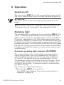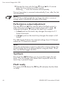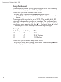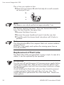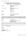
1
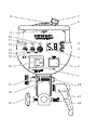
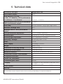
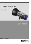
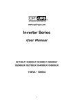
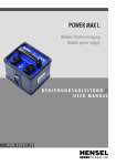
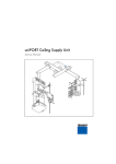
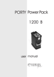
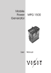
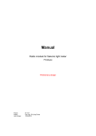
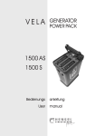
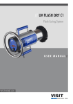
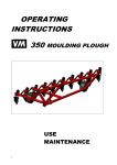
// Integra Mini 300
Kompaktblitzgerät
Compact flash
8
7
6
M a d e in Germ a n y
9
10
11
5
12
13
14
15
LAMP
SLAVE
4
TEST
OFF
16
115/230 V~ / 50-60 Hz
FUSE 4AF
ON
3
2
1
17
22
18
21
19
20
User manual Integra Mini 300
HENSEL-VISIT International GmbH
Robert-Bunsen-Str. 3
D-97076 Würzburg-Lengfeld
GERMANY
Tel. +49 (0) 931 27881-0
Fax: +49 (0) 931 27881-50
E-mail:
[email protected]
Internet:
http://www.hensel.de
© HENSEL-VISIT International GmbH, 2011
Distribution and reproduction of this document, and the use
and transfer of its content is not permitted unless such right is
explicitly granted. In case of violation, payment of compensation will be due. All rights reserved in case of patent approval or
registration of utility model (DIN 34-1).
Printing errors excepted and subject to modifications of technical data. The listed data are standard values and are not to
be misconstrued as guaranteed values in a legal sense. Values
can deviate depending on component tolerance.
98.0005.00
Effective date: 03/2011
HENSEL-VISIT International GmbH
1
User manual Integra Mini 300
1 Preface
Dear Photographer,
By purchasing a Hensel-Visit compact flash unit Integra Mini
300, you have purchased a high-quality and high-performance
product.
We want you to use this product successfully for years to come
and the following user information will provide you with the
necessary information.
Only by observing this information do you keep the warranty
effective, prevent damages, and extend the useful life of this
product.
The company Hensel-Visit took great care and observed all
pertinent regulations in order to manufacture a safe product
of highest quality. Stringent quality management procedures
ensure our high quality level, also regarding our large-scale
production series.
Please add your part and handle this unit with the necessary
care.
Do not hesitate to contact us if you have questions regarding
the use of this product.
We wish you great success and “good light“.
HENSEL-VISIT International GmbH
2
HENSEL-VISIT International GmbH
User manual Integra Mini 300
2 Content
1
2
3
4
Preface.............................................................................2
Content............................................................................3
Safety indication...............................................................5
General...........................................................................8
Description..................................................................8
Scope of delivery.........................................................8
5 Technical data..................................................................9
6 Summary of control elements..........................................10
7 Initial use........................................................................11
Acclimatization..........................................................11
Removal of transport cap...........................................11
Protective glass cover.................................................11
Insert flash tube.........................................................12
Inserting halogen lamp for modeling light...................12
Set-up .....................................................................13
Power supply.............................................................13
8 Operation......................................................................15
Switch on/off.............................................................15
Modeling light...........................................................15
Performance output adjustment..................................16
Test flash...................................................................16
Flash ready...............................................................16
Synchronization.........................................................16
9 Maintenance..................................................................19
Regular maintenance intervals....................................19
HENSEL-VISIT International GmbH
3
User manual Integra Mini 300
Replacing the fuses....................................................19
Replacement of flash tube..........................................20
Replacement of modeling light...................................22
Error messages..........................................................22
Warranty...................................................................24
Disposal....................................................................24
10Customer service points..................................................25
Manufacturer’s service...............................................25
Service points listed in the Internet..............................25
11Accessories.....................................................................26
12Subject index..................................................................27
13Declaration of Conformity...............................................28
4
HENSEL-VISIT International GmbH
User manual Integra Mini 300
3 Safety indication
In addition to the general rules for the use of electrical equipment, the following cautionary measures must be observed.
Please read and observe the following information before use.
Supply a copy of the safety information when selling, leasing, or
otherwise distributing this device.
ATTENTION!
Improper use of this device, disregard of the safety instructions,
or manipulation of the safety features can cause damage, bodily
harm, electric shock, or even death.
Proper use
Improper use
The compact flash unit Integra Mini 300 is intended for professional use by a photographer. It is only intended to be used with
the HENSEL-VISIT approved accessories listed in this manual.
The unit is not to be used for applications other than those described herein, especially not for other electrical applications.
Set-up and initial use
• Do not use the flash unit in environments that include explosion hazards.
• Make sure that the power supply corresponds with the information on the labelling.
• Compact flash units and generators must only be connected
to a grounded power supply.
• Check the protective conductor function before initial use.
• Only use plugs/connectors with intact contacts. Burned or
corroded plug-contacts can be the cause of fires. Defective
plugs can cause substantial damage to sockets.
• Do not connect accessories manufactured by other companies even when these look similar or alike.
• Avoid placing the cables on the studio floor to prevent tripping points and damage. If this cannot be avoided, make
HENSEL-VISIT International GmbH
5
User manual Integra Mini 300
sure that the cables cannot be damaged by vehicles, ladders etc.
• Damaged housings and cables need to be replaced immediately by an authorized service point.
• Keep minimum distances free surrounding the device to
ensure proper ventilation.
• Make sure ventilation slots are kept free during use to ensure proper ventilation.
• Do not place any objects into ventilation slots.
• Do not place any objects (coffee cups, containers filled with
liquids, etc.) on top of the device.
• Protect the device from moisture, dripping or splashing
water.
• Choose safe locations for placement of the device and
make sure that it cannot fall into pools or bodies of water.
• Keep sufficient safety distance from flammable materials
like decorations, papers, etc. to prevent a possible fire.
• Secure the unit with a back up support when attaching it
to the ceiling or an extension rod. Use the safety screw 20
inside the tilting bracket and also secure the device with
an arresting cable. Arresting cables can be ordered from
HENSEL-VISIT, see „11 Accessories“ on page 26.
6
HENSEL-VISIT International GmbH
User manual Integra Mini 300
Generators, compact flash units, and flash heads
ATTENTION!
Defective flash tubes and false handling can pose a mortal
danger.
A damaged flash tube can mean mortal danger because you
could come in contact with the electrodes conducting high voltage. Therefore, never touch unprotected electrodes inside the
flash tube!
Before replacing the flash tube or modeling light, the unit must
be switched off and disconnected from the power supply. Even
when the unit is disconnected from the power supply, in case of
a malfunction the condensers could still be highly charged. This
means touching the device could pose a life-threatening danger.
Halogen lamps and flash tubes can burst which is why they must
only be used with properly mounted safety cover.
ATTENTION!
Contact with capacitor voltage can pose a mortal danger.
Repairs or opening the housing must only be done by an authorized customer service provider.
Working with the device
• Do not flash directly into someone’s eyes from a short distance since this can lead to eye damage.
• Do not look directly into the flash tube or the reflector. The
flash could be triggered accidentally.
• Ventilate rooms regularly and sufficiently when using flash
units to prevent accumulation of high ozone levels which
may be caused by the operation of strong flash units.
• Cover devices not in use with a proper dust guard when
working in dusty environments.
HENSEL-VISIT International GmbH
7
User manual Integra Mini 300
4 General
Description
The Integra Mini 300 is a high-performance, entry-level compact flash unit. A bright, proportional modeling light, adjustable in 6 f-stops, high-quality performance electronics and an
EH-reflector connector are built-in to a sturdy metal housing.
Scope of delivery
Please check the scope of delivery before initial use.
Note:
The scope of delivery may vary depending on order configuration and country of delivery. Please see corresponding information on your delivery documents and order forms.
Standard scope of delivery includes:
• Flash tube, single-coated, plug-in type
• Modeling light, enclosed
• Tilting bracket, including umbrella holder
• Set of cables: power cord and sync cord
• Transport cap
• User manual
8
HENSEL-VISIT International GmbH
User manual Integra Mini 300
5 Technical data
Unit series/ unit type
Integra Mini 300
Performance output:
300 J
Lead aperture 100 ASA,
t 1/60, 12“-Reflektor, 100% performance
1 m distance / 2 m distance:
f 64 3/10 / f 32 3/10
Flash duration time (t 0,5s) in seconds at
100% performance output:
1/1900 s
Flash tube:
Item.-No. 9450401: plug-in type, single-coated
Minimum recharge time:
.25 s
Recharge time at 100% performance
output:
1.2 s
Flash performance adjustment:
10 - 5 = 6 f-Stop / 300 bis 9 J
Modeling light:
300W/G6.35/115V bzw. 300W/G6.35/230V
Modeling light adjustment:
OFF / proportional / AUTORED
Sync-plug/ -voltage:
6.3 jack plug, Mono / 5 VDC
Fuses:
F 4 A H
Power supply :
Multivoltage 110-230 V
Weight:
approx. 2.3 kg
Dimensions in cm (only casing):
LxWxH 23x12,3x14
Dimensions in cm overall:
LxWxH 26x12,3x18
Additional features:
Thermal check of performance electronics
- Daily flash counter/ reset function:
yes
- Integrated ventilator:
yes
- Photo cell, switchable:
yes
- Protective glass cover:
optional
- Display:
2x7-segment for flash performance/ daily flash count/
AUTORED/error codes
- User surface
Foil with touch keys, luminescent, HENSEL-user-logic
Item No.:
8370
Technical modifications excepted.
The listed data consists of typical values which can deviate depending on component tolerance.
HENSEL-VISIT International GmbH
9
User manual Integra Mini 300
6 Summary of control elements
1....... Power connector plug
2....... Power switch
3....... Display for selected energy/flash counter
4....... Adjustment key DOWN
5....... Adjustment key UP
6....... Handle bar
7....... Locking mechanism reflector holder
8....... Sync-plug
9....... Photo cell
10..... Display flash ready
11..... Display Slave (photo cell)
12..... Display modeling light
13..... Modeling light
14..... Slave (photo cell on/off)
15..... Test trigger flash
16..... Fuse and spares
17..... Locking mechanism umbrella holder
18..... Compartment for spare fuses
19..... Locking mechanism for stand
20..... Safety screw for suspended mounting
21..... Locking mechanism tilting-bracket
22..... Umbrella holder
10
HENSEL-VISIT International GmbH
User manual Integra Mini 300
7 Initial use
ATTENTION!
Please make sure that the unit is not connected to any power
supply when preparing for initial use.
Acclimatization
When relocating the device from and to locations with marked
temperature differences, place the unit inside the room where
it is to be used and first let it sit for some time. This prevents
moisture built-up which can cause creeping currents.
Removal of transport cap
The transport cap protects the flash tube / protective glass cover
during transport and when stored without a reflector.
ÂÂPush the locking mechanism of the reflector holder 7 against
the spring resistance up to the arrester.
ÂÂPull the protective transport cap straight out from the holder.
ATTENTION!
Do not switch on the device when the transport cap is attached.
The heat development of the modeling light could cause a fire.
Protective glass cover
ATTENTION!
Make sure that the flash tube and modeling light do not become
damaged during installation or removal.
Mount
The protective glass cover snaps into place via three pre-mounted springs.
ÂÂTilt the protective glass cover slightly and insert it into one of
the springs.
ÂÂThen snap the protective glass cover into the second spring
by applying light pressure, and continue this procedure until
it snaps securely into the third spring.
HENSEL-VISIT International GmbH
11
User manual Integra Mini 300
Disassemble
ÂÂTilt the protective glass cover slightly until it releases from
the first and then the second spring.
ÂÂRemove the protective glass cover by gently pulling it
straight out of the last spring.
Note:
Protective glass covers are available in different types. They can
change the color temperature as well as the light characteristics!
Insert flash tube
Compact flash units and the majority of flash units have plug-in
flash tubes which you can replace yourself. Please make sure
and observe all safety precautions.
Replacing the flash tube is described in detail in the chapter on
maintenance; see „Replacement of flash tube“ on page 20.
Inserting halogen lamp for modeling light
The halogen lamp for the modeling light is plug-in style. Observe the following instructions when inserting the enclosed
halogen lamp:
Note:
Avoid handling the lamp with your bare hands to prevent contaminating the glass of the lamp with the oil of your skin. This
would reduce the operational life of the lamp. Please use cotton
gloves.
Make sure you do not damage the flash tube when inserting it.
ÂÂPlace the pins in the lamp socket and carefully push down,
alternating the pressure on both pins until engaging the
arrester of the lamp socket.
12
HENSEL-VISIT International GmbH
User manual Integra Mini 300
Set-up
ATTENTION!
Please regard the general safety instructions reference set-up
location and surrounding area in the chapter „Set-up and initial
use“ on page 5.
Compact flash units can be used regardless of tilting angle.
Please note that extremely angled positions can cause faster
heat built-up in the device, especially in connection with long,
tubular attachments. In severe cases, this can trigger the automatic thermal switch-off function!
Power supply
ATTENTION!
Make sure that the power supply corresponds to the information on the labelling/ technical data sheet before connecting the
compact flash unit.
Compact flash units must only be connected to a grounded
power supply.
The type label is located at the bottom side of the housing. The
compact flash unit Integra Mini 300 is solely approved for use
with 115 V/230 V/ 50-60 Hz operation.
It features Multivoltage technology which means the unit automatically adjusts to the applicable voltage.
Fuse protection, building
Power sockets intended for the connection of devices have to be
protected with a minimum of 10 A.
Fuse protection, modeling light
The safety fuse ensures the protection of the modeling light.
The compact flash unit Integra Mini 300 is protected by a 4 A
fuse which reacts quickly (F 4 A H).
The listed safety values are valid when the device is used with a
300 W halogen lamp.
(Please note „Replacing the fuses“ on page 19).
HENSEL-VISIT International GmbH
13
User manual Integra Mini 300
Fuse protection, device
The inside of the unit contains a built-in fuse. When this fuse
responds, the unit is damaged.
ATTENTION!
Only authorized dealers may replace this fuse, see „10 Customer service points“ on page 25.
14
HENSEL-VISIT International GmbH
User manual Integra Mini 300
8 Operation
Switch on/off
The main switch ON/OFF 2 turns the compact flash unit on or off.
The unit is ready to flash when the ready indicator 10 lights up.
ATTENTION!
The power switch must be accessible and operational at all
times.
When you turn on the unit, it defaults to the last settings used.
This means, the unit “remembers” the settings at turn-off.
Modeling light
The modeling light is switched on by using the key LAMP 13. The
setting is indicated by LED 12 above the touch pad. If the LED
lights up permanently, the modeling light is always available at
full power, independent of the flash performance output. After
pressing the LAMP key a second time, the LED blinks slowly and
the light output of the modeling light is proportional to the flash
performance output. One more push of the key turns the modeling light off. If you press the key for one second, the AUTORED
function is activated (see below), no matter what mode you are
currently using.
Automatic modeling light reduction (AUTORED)
The compact flash unit’s modeling light is equipped with an
energy saving mode. After a pre-selected time, the light is
automatically reduced to level 9 when the setting is between
9.1 and 10. The default set by the manufacturer is 35 min.
This conserves energy and extends the lamp’s life span. If the
modeling light settings are lower than the above listed values,
the light is not dimmed. The original output is restored when
you touch any key.
This is how you set the switch-off time:
ÂÂPress the key LAMP 13 for one second.
The LED 12 starts blinking. The current switch-off time is
displayed in display 3.
HENSEL-VISIT International GmbH
43
User manual Integra Mini 300
ÂÂChange the time with the keys q 4 and p 5 in 5-minute
steps, up to a maximum of 90 minutes.
Selecting „--“ turns the function off completely.
Normal operation is resumed automatically 5 sec. after the last
use of any key.
Note:
Turn off the modeling light during longer breaks to conserve
energy and to extend the life span of the lamp.
Performance output adjustment
The keys q 4 und p 5 are used to adjust the flash output in
steps covering a performance output range of 6 f-stops. p
increases the output, q reduces the flash unit’s output.
• A short push on the touch key changes the output in 0.1
f-stop increments
• A longer push on the touch key changes the output in full
f-stops
The LED display 3 shows the selected settings from 5.0 (lowest
output) to 10 (maximum output).
Note:
When the performance output is reduced to a lower setting, the
stored energy has to be dumped before using the flash. To do
this, use the test trigger function.
Test flash
The touch key TEST 15 allows you to manually trigger the test
flash. The unit flashes with fastest flash sequence when the
touch key is pressed longer.
Flash ready
The green LED 10 above the TEST key 15 indicates that the flash
is ready.
44
HENSEL-VISIT International GmbH
User manual Integra Mini 300
Synchronization via cable
The compact flash unit is connected to the camera via synchronization cable by connecting the jack plug to the sync plug 8 on
the camera.
The synchronizing process employs the latest semiconductor technology and warrants reliable triggering of the flash
unit even when using older camera models with mechanical
contacts. The lower voltage of the sync plug makes safe and
reliable operation possible, also with the use of modern digital
cameras.
Note:
Based on the multitude of possible electronic circuits in different
cameras which are used for the synchronization, we are not liable for possible damage to a camera used for flash triggering.
Please contact the camera’s manufacturer before using a nonstandard camera for such purpose.
Synchronization via slave
The built-in slave 9 triggers the flash when light from another
flash is detected (slave-mode).
This mode of operation is activated/deactivated by using the
touch key SLAVE 14. The active setting is indicated via LED 11
above the touch pad.
The slave is an impulse photo cell. It only triggers the flash
when the striking light is brighter than the ambient light.
Note:
Make sure that no other bright, ambient light reaches the photo
cell. If this cannot be avoided, please use a cable or radio transmitter for synchronization.
Synchronization via radio transmitter
The optional radio-control set Strobe Wizard Plus Set can
be used to conveniently synchronize camera and flash unit via
radio remote control. See „11 Accessories“ on page 26.
ÂÂ In this set-up, you have to switch off the slave function with
the touch key SLAVE 14.
HENSEL-VISIT International GmbH
17
User manual Integra Mini 300
Daily flash count
The number of flashes which were triggered since last resetting
the counter is displayed on LED-display 3.
This is how you read the daily flash count:
ÂÂHold down the touch key SLAVE 14 for one second.
The LED 11 is blinking and Display 3 shows the number of
flashes.
The range of the counter is up to 9999. The double-digit LED
display 3 indicates the number in two steps. The numbers from
00 to 99 are shown in the first setting. The two additional digits
are shown when pressing the key p 5. The touch keys p 5 and
q 4 allow you to cycle through the double digit settings.
Example:
2. Setting 00
21
01
1. Setting
22
47
01
Total
22 flashes
2147 flashes
101 flashes
This is how you re-set the daily flash count:
ÂÂWhile in flash count mode, hold down the touch key LAMP 13
The display 3 is reset to 00.
18
HENSEL-VISIT International GmbH
User manual Integra Mini 300
9 Maintenance
ATTENTION!
The device must be disconnected from any power supply before
attempting any maintenance procedure.
The compact flash unit Integra Mini 300 does not require
much maintenance.
The outside of the unit must be regularly cleaned of dust and
dirt to guarantee the electrical safety of the device.
Note:
Only clean the unit with a dry cloth!
Regular maintenance intervals
National safety regulations require the maintenance and inspection of any electric device and equipment in regular intervals. Compact flash units, generators, and accessories must
be inspected in regular intervals to ensure safe operation. An
annual inspection of such devices ensures safe operation and
retains equipment value.
Replacing the fuses
ATTENTION!
Fuses must not be „patched up“ or otherwise bypassed. Only
use spare fuses that meet the below listed requirements and
have a fast response rating.
The compact flash unit must be disconnected from any power
supply before replacing a fuse.
Safety fuses for use with 300W halogen lamps: F 4 A H.
Only use fuses with a high switch-off capacity, labelling „H“,
according to EN 60127-2/1 or IEC 127-2/1. A wrong fuse can
increased the danger of the halogen lamp bursting and the
glow filament can burn out.
HENSEL-VISIT International GmbH
19
User manual Integra Mini 300
This is how you replace a fuse:
ÂÂOpen the fuse drawer 16 with the help of a small screwdriver and pull it out.
16
b
a
Note:
The drawer can only be pulled out approximately 1 cm.
The drawer contains two fuses. The rear fuse a is the active
fuse, the front fuse b is the spare fuse.
ÂÂRemove the blown fuse a a
ÂÂRemove the spare fuse b and insert it into the rear slot
ÂÂCarefully push the drawer back into place until it locks in
position.
Note:
The tilting bracket 18 of the compact flash unit contains additional spare fuses.
Refill your fuse supply and replace the missing spare fuse as
soon as possible.
Replacement of flash tube
The flash tube of the compact flash is plug-in style. In case of a
defect, it can be replaced by the operator.
ATTENTION!
Turn the unit off and disconnect it from any power supply before
replacing the flash tube. Wait at least 15 minutes before continuing the procedure and until any remaining condenser voltage
has dissipated.
Avoid handling the flash tube with your bare hands to prevent
contaminating the flash tube with the oil of your skin. This
would reduce the operational life of the flash tube. Please use
cotton gloves.
20
HENSEL-VISIT International GmbH
User manual Integra Mini 300
ÂÂRemove the protective glass cover; see „Protective glass
cover“ on page 11.
ATTENTION!
Should the glass body of the flash tube be broken, do not touch
the electrodes under any circumstance! In this case, use a fully
insulated pair of pliers to remove the damaged flash tube.
D
0,5
mm
A
D
C
B
ÂÂUnwind the ignition wire B from the connector pin C.
ÂÂCarefully pull the flash tube A out of the plug-in base D.
ÂÂInsert a new flash tube of the proper type into the plug-in
base D and push the flash tube into position until the arrester engages.
ÂÂNow pull out the flash tube approximately 0.5 mm so that
the glass body can expand when heating up.
ÂÂWind ignition wire B around the connector pin C.
Fitting flash tubes for the compact flash unit Integra Mini 300
can be found in the chapter „11 Accessories“ on page 26.
HENSEL-VISIT International GmbH
21
User manual Integra Mini 300
Replacement of modeling light
The halogen lamp for the compact flash unit’s modeling light is
plug-in style. In case of a defect, the lamp can be replaced by
the operator.
ATTENTION!
Turn the unit off and disconnect it from any power supply before
replacing the modeling light. Wait at least 15 minutes before
continuing the procedure and until the halogen lamp has cooled
off.
Avoid handling the lamp with your bare hands to prevent contaminating the glass of the lamp with the oil of your skin. This
would reduce the operational life of the lamp. Please use cotton
gloves.
ÂÂRemove the protective glass cover; see „Protective glass
cover“ on page 11
ÂÂCarefully remove the lamp from the plug socket
ÂÂInsert a new lamp of the correct type
Please make sure the lamp is properly secured when replacing
the modeling light; see „Replacing the fuses“ on page 19 .
Maximum modeling lights to be used are:
300W/G6.35/115V or 300W/G6.35/230V
The modeling light to be inserted has to match the power voltage.
Error messages
In case of an error, an error code is displayed in Display 3. In
such an event, follow these steps:
ÂÂTurn the unit off
ÂÂWait a few seconds
ÂÂTurn the unit on again
Should the error code persist, use the following checklist to see
if the malfunction can be corrected or contact a customer service point; see „10 Customer service points“ on page 25.
22
HENSEL-VISIT International GmbH
User manual Integra Mini 300
Error E4
Unit didn‘t flash.
In case of multiple flash units in operation, the misfiring of individual units is displayed.
Possible causes can be a burned out flash tube or a fault inside
the unit.
ÂÂReplace the flash tube if necessary or send the unit to an
authorized service dealer.
The error message disappears after a short while on its own.
Error E5
Unit is overheated.
When this error appears, the modeling light shuts off and the
unit stops flashing.
Possible causes can be extensive flash triggering, high surrounding temperature with full modeling light output, covered
air vents, ill fitted reflectors, or a defective ventilator (check by
listening).
ÂÂKeep the unit switched on so that the ventilator continues to
cool the flash unit.
Switching off the modeling light can improve things.
The error message disappears as soon as the unit has cooled
off again.
Error E1
Error E3
Error E6
Unit related errors.
This error code indicates a severe problem. The problem can
only be corrected by an authorized service dealer.
ÂÂSwitch off the unit immediately and discontinue using it.
ÂÂSend the unit to the next available service point and indicate
the error code.
Warranty
The warranty period for Integra Mini 300 depends on the
country of delivery.
You can obtain information pertaining warranty periods on the
web pages of the distributing companies.
HENSEL-VISIT International GmbH
23
User manual Integra Mini 300
Normal usage, meeting the safety requirements in the instruction manual, and adhering to the information therein, are
prerequisites for this warranty. Unauthorized manipulation and
tampering with the unit void any warranty claim.
Flash tubes, modeling lamps, protective glass covers, and defective power cables are excluded from any warranty.
The warranty includes replacement of faulty parts and the time
required for installation by a qualified technician.
Note:
You may send the unit free of charge to one of the customer
service points; see „10 Customer service points“ on page 25.
Please include a short description of the defect.
Disposal
The packing materials need to be sorted and recycled as necessary.
Retired and defective electronic equipment must be recycled in
accordance with regulation.
24
HENSEL-VISIT International GmbH
User manual Integra Mini 300
10 Customer service points
Manufacturer’s service
with 24-hour-express-service:
HENSEL-VISIT International GmbH
Robert-Bunsen-Str. 3
97076 Würzburg
Tel.: +49 (0)931 278 810
Fax: +49 (0)931 278 815 0
E-Mail: [email protected]
Service points listed in the Internet
Additional national and international service and distribution
addresses can be found on the web page of HENSEL-VISIT
International:
www.hensel.de
HENSEL-VISIT International GmbH
25
User manual Integra Mini 300
11 Accessories
Protective glass covers
Item No. 9454638: transparent, uncoated
Item No. 9454637: transparent, single coating
Item No. 9454639: matt, uncoated
Flash tube
Item No. 9450401: plug-in style, single coating
Halogen lamp for modeling light
Item No. 128 : 300 W/230 V
Item No. 1280 : 300 W/115 V
Reflectors and soft boxes
With small connector diameter (10 cm) for EH/Expert/Integra
line
Umbrellas
Spare fuses
Item No. 9412400 : Safety fuses F 4 A H
Sync cable
different length
Radio remote
Strobe Wizard Plus
Profoto Air
Arresting cable
Item No.: 769
Additional information concerning accessories can be found on
the web page of HENSEL-VISIT International: www.hensel.de
26
HENSEL-VISIT International GmbH
User manual Integra Mini 300
12 Subject index
D
Daily flash count 18
E
Energy saving mode 15
F
Flash ready display 15
Flash tube 7, 8, 9, 12, 20, 26
Fuses 10, 13, 14, 19
H
Halogen lamp 12, 13, 23
L
Listing 6, 13
P
Performance adjustment 16
Photo cell 10, 17
Power voltage 5, 9, 13
Protective glass cover 11, 21, 23
S
Safety fuse 13
Scope of delivery 8
Synchronization 17, 18
HENSEL-VISIT International GmbH
27
User manual Integra Mini 300
13 Declaration of Conformity
for Electromagnetic Compatibility and Safety
28
HENSEL-VISIT International GmbH