1
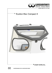
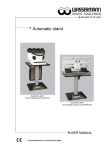
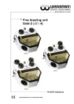
Fine blasting unit
Cemat-NT 4/3/2
Cemat- NT 4
Cemat- NT 3
Cemat- NT 2
USER MANUAL
Dear customer,
Thank you for choosing a product from the Wassermann range. Wassermann DentalMaschinen incorporates the highest standards of quality and the latest technology.
In order to enjoy maximum performance and years of trouble-free operation, please read
this user manual carefully before you connect this device and start work, and operate the
device according to the recommended guidelines. The operation safety and the
functionality of this device can only be guaranteed if you follow both the general safety
guidelines and the applying laws to prevent accidents as well as the precautions given in
this user manual. We are not liable for any damages which occur due to inappropriate
usage or faulty operation of this device.
Make sure that anyone using this device has read and understood this user manual.
Keep this user manual in a safe place where it can be referred to as required at
any time.
Company address:
Wassermann Dental-Maschinen GmbH
Rudorffweg 15-17
D-21031 Hamburg, Germany
Phone. : +49 (0)40 / 730 926 – 0 Fax.: +49 (0)40 / 730 37 24
E-mail: [email protected]
URL: http//www.wassermann-dental.com
.
Erstellt: 05.12.2012 / msc
Version: 2
Auftrag: 190990/066//190992/038//190993/018
Contents
1 Features....................................................................................................................................... 4
2 Safety guidelines.......................................................................................................................... 4
2.1 Safety symbols used in this manual.......................................................................................4
2.2 Safety guidelines................................................................................................................... 5
2.3 Responsibility for operation or damage.................................................................................5
3 Application.................................................................................................................................... 6
4 Before starting.............................................................................................................................. 6
4.1 Transport............................................................................................................................... 6
4.2 Storage.................................................................................................................................. 6
4.3 Installation............................................................................................................................. 7
5 Installation / Start-up .................................................................................................................... 7
6 Operation..................................................................................................................................... 8
6.1 General operating instructions...............................................................................................8
6.2 Filling with abrasive............................................................................................................... 8
6.3 Abrading................................................................................................................................ 9
6.4 Regulating the abrasive......................................................................................................... 9
6.5 Cleaning nozzles................................................................................................................... 9
7 Troubleshooting.......................................................................................................................... 10
8 Care and maintenance............................................................................................................... 11
8.1 Cleaning.............................................................................................................................. 11
8.2 Maintenance / Replacing worn components........................................................................12
8.2.1 Sleeves......................................................................................................................... 12
8.2.2 Specially coated protection shield.................................................................................12
8.2.3 Hoses.......................................................................................................................... 12
8.2.4 Pencils......................................................................................................................... 13
8.2.5 Lamp............................................................................................................................. 13
8.2.6 Nozzles......................................................................................................................... 14
8.2.7 Pressure regulator........................................................................................................ 14
8.3 Warranty ............................................................................................................................. 14
8.4 Spare parts.......................................................................................................................... 15
8.5 Scope of delivery / Accessories...........................................................................................15
8.6 Repairs................................................................................................................................ 15
9 Technical data............................................................................................................................ 16
10 EG-EC Conformity Certificate...................................................................................................17
1
Features
■ precision long-life fine blasting units for blasting, roughening and polishing
■ multifunctional fine blasting appliances with 2 to 4 chambers
■ even, pulse-free blast from 1–6 bar, low consumption
■ individual, pneumatic blasting control by means of key contacts directly on the stylus
■ permanent pressure system against pollution and dampness in the blasting medium
■ problem-free change of blasting medium for all usual blasting media sizes possible over
all chambers without use of tools
■ filter relief sand drawer for the catchment of coarse materials
■ with handy air-expellant jet for simple cleaning
■ specially coated protection shield for optimal visibility
■ practical colour coding system
■ high hygiene standard via changeable sleeves
■ no electronic components, with the exception of lighting
2
2.1
Safety guidelines
Safety symbols used in this manual
Warning!
This is a warning of risk situations and dangers.
Failure to observe this warning could be life-threatening. These warnings has to
be observed.
Information!
This symbol draws your attention to specific features that has to be observed.
2.2
Safety guidelines
Configuring and operating this equipment requires precise knowledge and observance
of the instructions in this user manual. The equipment is designed only for its intended
application.
WARNING:
Servicing and repairs should be carried out only by authorised specialists.
Disconnect the power plug before starting any maintenance work.
Make sure that the equipment is connected to the correct power source.
Warning: Never connect to an oxygen cylinder. Danger of dust explosion.
2.3
Responsibility for operation or damage
The responsibility for operating the device lies exclusively with the owner or user if said
device is incorrectly serviced, maintained or altered by persons not employed by an
authorised dealer or if the device is used in a manner contrary to its specified purpose.
The unit has to be maintained and operated in accordance with this user manual.
Wassermann Dental-Maschinen GmbH is not responsible for damage arising from the
nonobservance of these instructions.
Warranty and responsibility provisions contained in the sales and supply conditions of
Wassermann Dental-Maschinen GmbH are not extended by these instructions.
3
Application
The Cemat-NT family of fine-abrading units have multiple chambers for abrading,
roughening and polishing, and are used to bring a lasting finish to the workpiece.
The latest technology means that system blockages are virtually a thing of the past. The
instruments operate accurately and can prevent clumping of the abrasive. The new
techniques used break up the abrasive continuously. The entire system is under pressure
constantly and is ready for operation immediately. All Cemat-NT units are pneumatically
controlled, thereby avoiding problems with electronics.
Only use the device for this type of application.
4
4.1
Before starting
Transport
Before transporting the unit, ensure that it has been unplugged from the power socket.
Make sure that it is packed correctly in order to avoid accidental damage.
Be sure to check for any transport damage when unpacking the goods. Note down
any damage if found.
4.2
Storage
If the unit is to be stored for an extended period, protect it from moisture and dust.
4.3
Installation
Open the box, remove the packing materials, and carefully lift out the device and
accessories. Check the included accessories.
The device has to stand horizontally on a steady and even surface.
Install the device in a place where it will not block the working area and the
functionality (take the dimensions into account).
Do not install the unit outdoors or in places without proper ventilation.
Before start-up, be sure the device reaches room temperature.
5
Installation / Start-up
Before starting the unit, connect up the following:
•
Connect the unit to the compressed-air line.
•
The fine blasting unit has to be connected to an external suction unit. The nozzle is
at the lower rear.
•
Finally, insert the power plug into the socket, making sure that the mains and the
unit operate on the same voltage.
•
Fill the abrasive tanks.
•
Flip the (green) rocker switch.
•
The unit is ready for use as soon as it reaches operating pressure.
•
The abrasion process is blocked until the observation flap is closed.
Warning: Never connect to an oxygen cylinder. Danger of dust explosion.
6
6.1
Operation
General operating instructions
All instructions for using the unit, whether in verbal or written form, are based on our
own experience and experimentation and can only be regarded as guidelines.
All abrasive tanks are colour-coded to match the pencils in the abrasion chamber. Thus, if
you use the blue pencil, it will be fed with abrasive from the blue tank.
The instrument will operate only with the observation flap closed. A safety switch
cuts power to the system if the flap is open.
6.2
Filling with abrasive
The instrument must be switched off before you fill it.
The tanks can only be opened after the pressure has been released. You do this by
pressing the coloured point in the lid until you no longer hear air coming out. The lid can
then be unscrewed and the container filled with abrasive.
Pay attention of the maximum filling: the receptor nozzle has to be free of material.
All tanks accept all grain sizes. Make sure that the grain size of the medium being added
matches that of the material already in the tank.
The nozzle and the grain size must also match. You should use a 0.8 mm nozzle when
working with glass beads. A 1.2 mm nozzle is recommended for use with irregular bead
sizes. Before replacing the lid, make sure that the thread and sealing surfaces are free of
abrasive. The instrument is ready for use when all tanks have been sealed.
6.3
Abrading
You hold the pencil in your hand like a stylus. One finger must be placed at the top end of
the flat recess. You then apply light finger pressure to initiate the abrasion process.
6.4
Regulating the abrasive
The pressure regulator at the rear of the instrument is set at the factory to 6 bar. This
setting must not be changed. Adjustment of the abrasive pressure is done only using the
black knobs at the top. You adjust the pressure by pulling the knob out and turning it to the
left (to reduce the pressure) or to the right (to increase the pressure). You
then push the knob in again. The set pressure can be read on the pressure gauge.
Changing the pressure varies the abrasive feed velocity and the amount of abrasive used.
6.5
Cleaning nozzles
The instrument is fitted with a compressed-air nozzle for cleaning the inner area and the
workpiece. You operate it by lightly bending the front section of the rubber pencil.
7
Troubleshooting
Fault
Irregular abrasive flow
No abrasive flow
Falling pressure, low jet
pressure
Cause
Too little abrasive in tank or
pencil nozzle too small
or abrasive wet
Tank empty
Nozzle and/or hose blocked
Remedy
Fill tank
Use larger nozzle
Replace with dry abrasive
Fill tank
Unscrew nozzle from pencil and
clean (eg, with a needle) and try
process again; abrasive must flow.
If necessary, kink hose briefly to
increase pressure.
Filter blocked and/or seized Contact our Service department
If the above recommendations do not solve the problem, contact your dental depot
or our service department.
Note:
Blockages are mostly the result of impure or clumped abrasive. If the sand is absorbing
moisture, check the water separator and your compressor.
8
8.1
Care and maintenance
Cleaning
Disconnect the power plug before starting any maintenance work.
The identification plate has always to be kept in easily legible condition and has
not to be removed.
Remove external dirt from time to time with some form of cold cleaner.
Use only cold cleaners to avoid damaging the paintwork or removing the lettering.
The equipment should be cleaned at regular intervals to ensure trouble-free operation.
It requires only normal cleaning (sponge, damp cloth, mild detergent) and no further
chemical additives.
The interior of the chamber can easily be cleaned using the compressed-air nozzle. Fine
dust will be removed by the suction system.
Coarse abrasive, which cannot be removed by the suction system, will fall through the
grate and into the drawer.
In this way, the suction filter is not overloaded and the chamber remains free of abrasive.
The drawer must be removed completely for emptying.
11
8.2
Maintenance / Replacing worn components
8.2.1
Sleeves
The sleeves can be replaced by gloves. The procedure is the same:
1. Remove the ring with the spring inside the chamber.
2. Remove the old sleeve. Install the new sleeve on its mount so that it faces the wall.
3. Replace the ring with the flat side facing the wall.
8.2.2
Specially coated protection shield
1. Open the flap and undo the three thumbscrews on the disk.
2. Remove the aluminium guides.
3. Tip the disk forward and remove it from the front slot. Please take care of the
spacer reels.
4. Replace it with the new disk.
5. Reassemble in reverse order.
8.2.3
Hoses
Before replacing the hoses, disconnect the power plug, undo the compressed-air
line and release the pressure in the tanks.
1. Remove the grate from the chamber, then undo the thumbscrews and remove the
pencil mount.
2. Remove the grate.
3. Rest the instrument on its side so that you can reach under it.
4. Use a no. 17 spanner to undo the black nut so you can unscrew and remove the
black hose from the tank.
5. To remove the white control hose, grip it by the brass end, depress the brass ring
on the valve and then remove the hose.
6. Pull the silver grip on the thrust valve. Insert your other hand through the access
hole and pull the hose into the central chamber.
12
7. The hose is directed from the chamber through the port to the thrust valve, and then
guided onto the nipple on the tank (do not forget the nut and the plastic cap).
Before tightening the nut, make sure that the woven casing has been pushed fully
over the rubber. Tighten the nut to the stop.
8. Insert the white hose only up to the stop.
9. Set the instrument upright again and re-install the pencil mount and the grate.
10. Make sure that the hoses run under the screen grate.
8.2.4
Pencils
1. Undo the silver cap on the end of the pencil.
2. Remove the rubber hose and the white control hose.
3. Reassembly: slip the silver cap and the plastic ring onto the new hose. The recess
in the plastic ring must match up with the control hose. Slip the black, nylonsheathed rubber hose onto the nipple on the pencil. Then push the white control
hose into the small opening up to the stop. Push the plastic ring firmly onto the
pencil.
4. Slide the woven casing over the rubber and tighten the silver cap.
8.2.5
Lamp
1. Remove the power plug before replacing the lamp. The lamp is located top rear in
the abrasion chamber.
2. Undo the knurled screws and then remove the guides and disk.
3. Turn the lamp to the left and remove from the socket.
4. When inserting a lamp, make sure you hear it click into place.
5. When inserting the disk, first locate it behind the lip at the front and then press it
down into place. Insert the guide with the bend to the back and then tighten the
knurled screws.
13
8.2.6
Nozzles
You has to ensure that the nozzles suit the size of the abrasion media used. Replace
nozzles by unscrewing the current nozzle and screwing on a new one. Important: Before
you screw on the new nozzle, use a short burst of compressed air to clear any residual
abrasive from the hose.
Warning! Before you use a 0.4 mm nozzle, you will need to change the
receptor nozzle. Please order this as well to avoid blockages occurring.
8.2.7
Pressure regulator
There is a pressure regulator with integrated water separator at the rear of the instrument.
This ensures that no moisture from the compressor enters the instrument’s circulation
system. It should be checked from time to time and emptied when it reaches its maximum
level. To do so, release the grey outlet knob so the water can flow down into a container.
8.3
Warranty
The warranty period for our equipment is 12 months. If faults occur within the
warranty period, contact your dental depot or get in touch directly with our service
department.
Your equipment should only be operated in perfect condition. If faults occur which
could harm operators or third parties, the unit should not be used until it has been
fixed.
This warranty does not cover damage caused by improper use, external mechanical
causes, transport damage or interference with the unit by unauthorized persons.
14
8.4
Spare parts
If necessary please contact our service hotline phone:
0049 (0)40 / 730 92 6-0
8.5
Scope of delivery / Accessories
Incl. in delivery
PVC hose Ø 8x6 textile (blue), 2 m
Supply line
Cemat-NT 4 including 4 fine blasting jets
0.6 (yellow), 0.8 (blue), 0.8 (red), 1.2 (green)
Cemat-NT 3 including 3 fine blasting jets
0.6 (blue), 0.8 (red), 1.2 (green)
Cemat-NT 2 including 2 fine blasting jets
0.8 (red), 1.2 (green)
Item no.:
320026
592012
190992
Accessories
Automatic stand
PVC hose Ø 8x6 textile (blue), per meter
Sleeve
Spare fine blasting jet 0.4 mm
Spare fine blasting jet 0.6 mm
Spare fine blasting jet 0.8 mm
Spare fine blasting jet 1.2 mm
Item no.:
190420
320026
190175
190254
190250
190251
190252
190990
190993
We recommend the use of Wassermann blasting materials and our suction unit
SG10 / SG-20. They are very effective and have large filter capacities.
8.6
Repairs
Servicing or repairs to the unit has only to be carried out by qualified technicians.
Only original spare parts are to be used. Responsibility for the product is voided
if unauthorised persons alter it or if inappropriate components are installed.
15
9
Technical data
Cemat-NT 4
Cemat-NT 3
Item no.: 190992
Item no.: 190990*
Item no.: 190989***
Item no.: 190993**
220–240 V / 50/60 Hz / 115 V / 60 Hz ***
0.2 A / 0,4 A ***
8A
Cemat-NT 2
Voltage
Power consumption
Female connector
power consumption max.
Output
WxHxD
50 W / 24 W ***
550 x 480 x 610 mm
430 x 480 x 610 mm*/ **
42.6 kg, 37.7 kg* / ***, 34.0 kg**
≤ 70 dB (A)
800 cm³ = 1.2 kg
3-6 bar
1-6 bar
75 mm
Weight
Sound level
Tank capacity
Compressed air connection
Working pressure
Extractor nozzle
The noise level of the unit amounts to ≤ 70 dB (A).
The technical data are subject to change without prior notice.
16
10
EG-EC Conformity Certificate
in accordance with 2006/95/EG (low-voltage guidelines) and 2004/108/EG (EMV
guidelines) and 2006/42/EG (machinery guidelines)
Manufacturer:
WASSERMANN
Dental-Maschinen GmbH
Rudorffweg 15 - 17
D-21031 Hamburg
Model:
CEMAT-NT 4
CEMAT-NT 3
Product description:
Item No. 190992
Item No. 190990
Item No. 190989
Item No. 190993
CEMAT-NT 2
Applicable
standards:
Fine blasting unit
for dental
applications
DIN EN 61010-1
DIN EN 61000-6-3
DIN EN 61000-6-1
DIN 45635-1
DIN EN 60335-1
Hiermit wird bestätigt, dass die oben bezeichnete Maschine den genannten EG-Richtlinien
entspricht. Diese Erklärung wird ungültig, falls die Maschine ohne unsere Zustimmung
verändert wird.
This is to confirm that the above mentioned machine complies with the described EC
rules. This declaration becomes invalid if the machine is modified without our approval.
Cette machine est conforme aux normes en vigueur de la Communité Européene. Cet
avis est nul et non avenant si cette machine est modifiée sans notre accord.
Esta máquina, anteriormente mencionada, cumple con los limites requeridos por el
reglamento EC. Ahora bien, esta declaración quedará invalidada en caso de realizar
modificaciones al aparato sin nuestra aprobación.
Hiermee wordt bevestigd dat bovengenoemde machine voldoet aan de voorgeschreven
EU normen. Deze verklaring verliest geldigheid als er zonder onze uitdrukkelijke
toestemming wijzigen aan de machine worden aangebracht.
Place, date: Hamburg, 05.12.2012
Company stamp:
Signature : ________________________
Wilfried Wassermann
17
(Managing Director)
Notes:
18
19