1
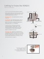
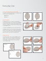
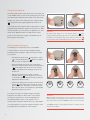
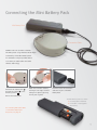
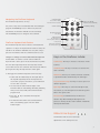
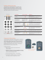
MAESTRO™ Cochlear Implant System
QuickGuide
RONDO Audio Processor
Getting to Know the RONDO
The parts and functions
Battery pack
Control Unit: The control unit is just like a tiny computer.
Red indicator lights
Inside, an electronic chip controls the entire system. It can hold
several different programs (also called ‘maps’), which contain
the specific hearing settings for each user.
Microphone port: This tiny opening is where sound enters
the processor.
LED indicators: These small red lights indicate a variety of
Microphone /
Microphone cover
status and error conditions. They should illuminate when the
processor is first turned on and will indicate which position is
currently active (with 1, 2, 3 or 4 quick blinks).
Attachment clip fixture
(available on both sides)
Control Unit
Integrated telecoil: The telecoil is located in the
Attachment clip
control unit and requires no additional parts or cables.
Select telecoil settings using the FineTuner remote control
to reduce background noise with hearing aid compatible
Switch
(ON / OFF / Unlocked)
telephones and induction loop systems.
Mini Battery Pack (optional): The standard input jack on
the Mini Battery Pack provides the widest variety of connectivity
with different audio devices. The input jack is the same three-pin
Release lever
port that is used with hearing aids – which allows new CI users
to preserve their initial investments by continuing to use their
personal assistive devices. (See page 5.)
Air inlets
TIP
An easy way to remove batteries
from your RONDO – simply use
the bottom side of the processor to let
the magnet lift the batteries out!
2
Everyday Use
Turning the audio processor ON and OFF
The switch on the battery pack functions as an ON / OFF switch.
You may select the following positions:
RONDO OFF: O
RONDO ON: |
OFF
RONDO Protector
ON
The RONDO protector is a soft silicone cover intended to
absorb mechanical impact on the housing in case the RONDO
is dropped. The protector reduces the risk of damage to the
audio processor. MED‑EL strongly recommends that you always
use the RONDO protector.
To assemble the RONDO protector, insert the narrow end of
the RONDO audio processor into the protector. Next, pull the
protector over the opposite side so that the slide switch rests
1
2
in the cutout section of the protector. The back strap of the
protector should rest across the top of the processor.
Attachment Clip
The attachment clip is used to secure the RONDO to hair or
clothing to reduce the risk of damaging the audio processor
should it come off and drop on the floor or another hard
surface. MED‑EL strongly recommends that you always
use the attachment clip.
Small clip to
attach to hair
1
2
3
4
Large clip to
attach to clothing
3
Changing the Batteries
The battery pack features a tiny release lever on the right side
of the ON / OFF switch. To remove the battery pack, press down
the release lever and push the slide switch to the right until it
engages. The arrow on the switch faces the unlocked symbol
(
1
). Now pull the battery pack slightly back and lift it off.
2
To assemble the battery pack, hold the battery pack at a slight
2
1
downward angle and push it straight onto the processor. When
the battery pack rests on the processor, slightly press it down
IMPORTANT
and move the ON / OFF switch to the OFF position (center
The switch must always be in the unlocked position (
position). The release lever engages automatically and the
removing / attaching the battery pack. Do not use excessive force. To move
battery pack is locked again.
the switch to the unlocked position, press down the release lever ( 1 )
) when
on the right side. Hold it down while pushing the switch to the right ( 2 ).
How to change the magnet
A small magnet is located in the center of the RONDO
to hold it in place on the head over the implant package.
The magnet can be changed to adjust the magnet strength
to your needs.
– Hold down the release lever ( 1 ) and push the switch
( 2 ) to the unlocked position ( ). Remove the battery
pack to access the magnet insert.
1
2
1
2
3
4
– Grasp the magnet insert at the two serrated spots
and turn it counter clockwise until the unlocked symbol
( ) on the magnet faces the arrow on the housing
bottom. The magnet insert disengages and can now
be lifted out.
– Take the new magnet insert. Hold it so that the
unlocked symbol ( ) on the magnet faces the arrow
on the housing bottom. When positioned correctly, the
magnet insert glides in easily.
– Now turn the magnet insert clockwise until the locked
symbol ( ) faces straight down towards the arrow on
the housing bottom. The magnet is inserted correctly
when the four circles on the magnet are symmetricallysoftsoftsoft
soft
aligned with regard to the arrow.
standard
standard
standard
standard
strong
strong
strong
strong super
super
strong
super
strong
super
strong
strong
Four magnet strengths are available. Magnet strength is
indicated by the number of white circles on the magnet.
Important
The magnet strength chosen should be appropriate for
MED‑EL strongly recommends that you do not change the magnet insert
the individual patient, that is strong magnets, are not
yourself, but have your audiologist or clinical staff do it. If you notice any
recommended for patients with thin skin (e.g. young children
4
signs of skin irritation around the RONDO, contact your clinic or CI center.
or very slim patients), as excessive magnetic attraction could
Your RONDO contains a strong magnet. Keep clear of metallic items as
potentially increase the likelihood of skin irritation.
they attract the magnet.
Connecting the Mini Battery Pack
Mini Battery Pack
Connection Cable
RONDO users can connect to devices
like FM systems using the Direct Audio Input
connectivity of the Mini Battery Pack.
Its standard 3-hole pin provides access
to a variety of audio cables and other
wireless technology.
1
2
1
Hold down the release lever ( 1 )
and push the switch ( 2 ) to the
unlocked position ( ).
Remove the battery pack.
2
Attach the connection cable by
inserting it at an angle, and then
locking it into place by pressing
the two parts together.
3
Insert the end of the connection
cable into its port on the Mini
Battery Pack.
The Mini Battery Pack uses either:
(1) a rechargeable PowerPack
(2) a standard or rechargeable
AAA battery
For connecting with audio cables
or other Direct Audio Input
accessories, see page 11.
1
2
5
Using the FineTuner
The FineTuner remote control is an accessory device that
can be used to optimize the audio processor in changing
daily listening situations. The RONDO processor has an
ON/OFF switch. All other functions are accessed with
the FineTuner, which transmits commands to the
RONDO processor.
The FineTuner is not required for everyday use of the audio
processor. When the RONDO is turned on, it will return to
the same program, volume and sensitivity settings that were
in use when it was turned off. The FineTuner is configured
for its designated RONDO processor, so that only the target
RONDO processor can execute a command from the FineTuner.
The slim FineTuner™ is
credit-card sized with a
thickness of only 6 mm.
The typical maximum operating distance between the FineTuner
and RONDO processor is approximately 80 cm (2.6 ft.).
This range could be decreased near electrical equipment.
How to configure the FineTuner
When to configure the FineTuner
Once synchronized, the RONDO and Fine Tuner stay in
For users with a cochlear implant on each ear (bilaterally
synchronization until one of the two pieces of equipment need
implanted), one FineTuner can be used for both ears.
to be changed. It should only occasionally be necessary to
However, a FineTuner can only be synchronized with one
synchronize the FineTuner and audio processor. Examples
audio processor for each ear.
include use of a back-up audio processor or second FineTuner.
The FineTuner only needs to be configured:
To configure the FineTuner:
1.Turn off your RONDO processor.
2.Place the RONDO processor over the
MT key on the FineTuner.
3.Turn on the RONDO processor.
4.The audio processor and the FineTuner will
be synchronized automatically.
5.Successful synchronization is indicated by a
short blinking signal of the two amber indicator
lights on the FineTuner.
6
1.At the initial audio processor fitting.
2.When using a different or additional processor
(e.g., back-up, loaner or replacement, bilateral).
3.When using a different FineTuner.
Navigating the FineTuner Keyboard
The FineTuner keyboard has 15 keys.
Any of these keys can be deactivated when the audiologist
indicator lights
one red LED for alarms
two amber LED for functions
volume setting
return to default
volume and sensitivity
sensitivity setting
programs the RONDO processor. When a key has been
deactivated, the FineTuner will still send the command,
program selection
four settings
input selection
FineTuner Keyboard Lock Feature
The FineTuner keyboard can be locked to avoid accidental
M: microphone only
MT: microphone with telecoil
T: telecoil only
processor selection
left, both (bilateral), right
6.3 mm thickness
but the RONDO processor will ignore the command.
operation of a key. If the keyboard lock feature is active, the
red LED of the FineTuner will blink once every time a key is
pressed. This indicates that the command cannot be sent.
Changes to settings can still be made while the keyboard
Keys on the FineTuner include:
lock is active. To activate a certain function while the
keyboard lock is active, press the desired function key twice.
Volume keys: Two keys to increase or decrease overall
The first click temporarily unlocks the keyboard, and the
loudness.
second click executes the command. After 10 seconds without
pressing another key, the keyboard lock is active again.
To disengage the automatic keyboard lock if necessary:
1.Double-click the bilateral key. The first quick click of
this key will temporarily unlock the keyboard. The
second time you press this button, you should hold it
for more than 5 seconds.
2.The red and both amber indicator lights of the
FineTuner will both start blinking alternately, indicating
that you have successfully entered the FineTuner’s
program mode.
key to deactivate the keyboard
3.Press the
lock feature.
4.The FineTuner will confirm successful deactivation
with a short blinking signal of the two amber
indicator lights.
Sensitivity keys: Two keys to increase or decrease the
audio sensitivity.
Default key: This key sets volume and audio sensitivity
to predefined values determined by the audiologist.
Program Selection keys: Four keys to access up to four
different programs.
Input keys: Three keys to select the microphone (M),
the telecoil (T) or the microphone and telecoil together
(MT) as the signal source.
Processor keys (for bilateral users): The Processor
Selection keys allow selecting the left, right or both
processors. The keys are also used to activate or deactivate
the keyboard lock feature.
Bilateral User Support
One FineTuner remote control can make
adjustments to two audio processors!
7
FineTuner Indicator Light Signals
The FineTuner has 3 indicator lights that can provide useful
information about how the FineTuner is operating. Indicator
lights are located above the FineTuner keyboard and include
a red LED in the center with amber LEDs to the left and right.
These LEDs can provide the following information:
FUNCTIOn
RED (center)
AMBER
(left side)
AMBER
(right side)
LIGHT PATTERN
Keyboard
Locked
Transmitting
Information
In order to conserve power, the red indicator light will go off
after 5 seconds even if the key is still pressed.
Left or right (or both)
lights blink according to
the side mode of the
FineTuner.
Indicator lights will blink when signals are transmitted
(the indicator light blinking corresponds to the processor being
modified - either right, left or both sides for bilateral users.)
To save energy, the FineTuner stops transmitting (and the
indicator light stops blinking) after 3 seconds, even if the
key is still pressed.
To send commands to either the left or right side, press the
corresponding button and the amber light will illuminate.
Switching Sides
To switch both sides at once (for bilateral users) press the
button in the center. Both amber lights will illuminate.
(+5 seconds)
Programming
Mode
Press for more than 5 seconds to enter the programming mode.
The three indicator lights will start flashing alternately.
When the red indicator light is on, the two amber indicator
lights are off and vice versa.
Low Battery
Configuration
Successful
MEANING
If you press a key while the keyboard is locked, the red
indicator light comes on.
blinks 3 times
illuminates for one second
If a low battery status is detected, the red indicator light
(center) will blink in a regular pattern - 3 blinks at a time.
If configuration of your FineTuner was successful, or if the
automatic keyboard lock feature was successfully activated/
deactivated, both amber indicator lights will illuminate for
approximately one second
Changing the FineTuner Battery
To conserve power, the FineTuner will only transmit a command for
a few seconds. For this reason, you should press the desired key
once for every change you wish to make. The FineTuner battery
status is checked after each transmission. When the batteries
are low, a red indicator light on the FineTuner blinks three times,
indicating that the battery should be changed. The FineTuner
battery should last for at least several months.
To change the battery:
1.Open the lid on the back of the FineTuner with a
small screwdriver.
2.Replace the used button battery (type CR2025) by removing
it with the coil magnet or by gently shaking it into your hand.
Try not to touch the battery contacts.
3.Insert the new battery with the “+” sign facing up.
4.Close the lid by carefully inserting it on the right side,
then sliding it in place and tightening the screw.
8
Insert the new battery with
the “+” sign facing up.
Connect to the World
The RONDO features an integrated state-of-the-art telecoil
and a Mini Battery Pack for completely wireless access to a wide
variety of telephones, public sound systems, MP3 players and
direct-link systems – such as FM and Bluetooth® systems. You can
access induction loop technology at the simple touch of a button,
and a standard input jack means you can connect the same
FM receivers used with many hearing aids.
9
Using Telecoil
Delivering sound by magnetic induction
A telecoil is a special circuit inside the audio processor
designed to pick up electromagnetic signals. These signals –
or induction signals – are wirelessly transmitted to the
audio processor by using a neckloop or induction
loop system.
A neckloop is a wire worn comfortably
around the neck that transmits signals
to the processor.
Simply plug the telecoil accessory
(neckloop) into the audio device or ALD receiver and select
“T” or “MT” on the FineTuner. Adjust volume as needed.
For Induction Loop Systems, simply position yourself within
the listening area and select “T” or “MT” on the FineTuner.
Adjust volume as needed.
Tip:
Electromagnetic technology is susceptible to
&Play
Plug
Using a third-party telecoil accessory:
interference, which can cause some intermittent
humming while using a telecoil accessory.
Humming usually occurs when the user is
positioned near a source of electromagnetic
energy (power lines, fluorescent lighting,
computers, appliances, electronics, etc.).
Simply moving away from the source can remedy
interference issues if they occur.
Insert the telecoil
device’s 3.5 mm plug
into the headphone
jack of the music
device.
M: Microphone
On your FineTuner,
press “MT” or “T” to
activate telecoil.
Place the telecoil
accessory around
neck (neckloop)
or on the ear
(earhook).
T: Telecoil Only
MT: Microphone and Telecoil Together
These keys are independent of all other processor settings
and can be used with any program selection (1, 2, 3 or 4),
volume, or sensitivity setting.
10
Direct Audio Input
With the Mini Battery Pack
By connecting to the Mini
Battery Pack, RONDO users have
multiple connectivity options with
its universal 3-pin connector.
FM receivers - Many FM receivers and
direct-link devices with the standard
3-pin connector (e.g., Phonak MicroLink
MLxS) can be used with the Mini
Battery Pack. Turn the audio processor
off, insert the receiver, and turn the
processor back on. When the FM system is activated, the
audio processor will automatically integrate the sound signal.
Audio Cables - Connect the 3-pin
connector of the MED-EL Audio
Cable (gray end) to the openings at
the bottom of the Mini Battery Pack.
Mind the orientation of the three pins
and do not use excessive force when
connecting the cable. Connect the audio plug
(yellow or red end) to the audio output
of the battery-powered device.
Tip:
Direct connections almost always provide a
distortion-free, clear listening experience not
&Play
Plug
Using third-party FM receivers:
Attach the RONDO
connection cable
and plug into the
Mini Battery Pack.
Insert receiver’s
3-pin plug into
the port of Mini
Battery Pack.
limited by interference issues that telecoil
accessories may sometimes encounter. However,
Refer to the FM
system user manual
for options to
adjust FM setting
if necessary.
Using MED-EL’s direct-connect audio cable:
FM systems themselves may be susceptible to
interference from the FM signal.
Audio cables running from the processor can be
somewhat restrictive since this is not a wireless
option. Extensive use of audio cables can also
slightly decrease processor battery life.
Attach the RONDO
connection cable
and plug into the
Mini Battery Pack.
Insert the audio
cable’s 3-pin plug
into the port of
Mini Battery Pack.
Insert the audio
cable’s 3.5 plug into
the headphone jack
of the music device.
11
MED-EL Medical Electronics
MED-EL Corporation, USA
Headquarters
2511 Old Cornwallis Road, Suite 100
Fürstenweg 77a
Durham, NC 27713, USA
6020 Innsbruck, Austria
Tel.: 919-572-2222
[email protected]
Fax: 919-484-9229
Toll Free: (888) MED-EL-CI (633-3524)
[email protected]
24307 r1
medel.com
For information on potential risks and
contraindications relating to implantation, please visit
www.medel.com/us/isi-cochlear-implant-systems