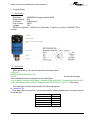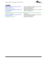
1
Centre de Brest
Département Recherche et Développements Technologiques
Programme 8, projet 8
Observatoires fond de mer pluridisciplinaires
NEPTUNE CANADA : TEMPO-MINI V2 documentation
établi le :
par :
Réf :
n° analytique :
Indice :
31/01/11
J. Legrand
RDT/EIM/10-053
A080806
d
Diffusion :
IFREMER
Auffret Yves (RDT/EIM)
Bescond Tanguy (RDT/EIM)
Blandin Jérôme (RDT/IPR)
Caradec Florian (RDT/EIM)
Coail Jean-Yves (RDT/EIM)
Delauney Laurent (RDT/EIM)
Laës Agathe (RDT/EIM)
Le Gall Christian (EEP/LEP)
Sarradin Pierre-Marie (EEP/D)
Sarrazin Josée (EEP/LEP)
Diffusion :
confidentielle NEPTUNE CANADA
Pirenne Benoît (Neptune Canada)
Hasanen Reece (Neptune Canada)
Pautet Lucie (Neptune Canada)
Lavallee Tim (Neptune Canada)
Wallace Kim (Devocean)
Williams Jason (Highland-Tech)
restreinte ❏
libre
❏
NEPTUNE Canada : TEMPO-MINI V2 Documentation
DOCUMENT VERSIONS
Version
Date
Description
Reference secretariat
A
19/02/10 Document creation
RDT/EIM/10-015
B
Modification §10.1 :add of a CHLORINATION
03/12/10 initialisation phase
§10.3 : inversion of the chlorination command
RDT/EIM/10-053
C
12/01/11 Connectors added on the synoptic drawing (§2)
-
D
31/01/11 Chemini data description completed (§9.5)
-
SUMMARY
1 - Introduction...................................................................................................................................4
2 – Synoptic drawing..........................................................................................................................5
3 – The electronic unit........................................................................................................................6
3.1 Ethernet switch....................................................................................................................................7
3.2 Barionet n°1 .........................................................................................................................................7
3.3 Barionet n°2 .......................................................................................................................................10
4 – Oil filled junction box ................................................................................................................12
5 - Camera.........................................................................................................................................13
5.1 – Information.....................................................................................................................................13
5.2 - Technical specifications ..................................................................................................................13
6 – Lights ...........................................................................................................................................15
6.1 – Information.....................................................................................................................................15
6.2 – Example...........................................................................................................................................15
7 – Oxygen Sensor ............................................................................................................................16
7.1 – Information.....................................................................................................................................16
7.2 – Data frame ......................................................................................................................................16
7.3 – Example...........................................................................................................................................17
8 – T° probe.......................................................................................................................................18
RDT/EIM/10-053
2/25
31/01/2011
NEPTUNE Canada : TEMPO-MINI V2 Documentation
8.1 – Information.....................................................................................................................................18
8.2 – Example...........................................................................................................................................18
9 – CHEMINI Chemical analyser...................................................................................................19
9.1 – Information.....................................................................................................................................19
9.2 - CHEMINI main specifications.......................................................................................................19
9.3 – CHEMINI measurement schedule................................................................................................19
9.4 - Command frames............................................................................................................................20
9.5 - Data description ..............................................................................................................................20
9.6 – Example...........................................................................................................................................23
9.7 - Time stamping.................................................................................................................................23
10 – Chlorination..............................................................................................................................24
10.1 – Information...................................................................................................................................24
10.2 - Synchronisation with the Optode ................................................................................................24
10.3 - Example .........................................................................................................................................24
RDT/EIM/10-053
3/25
31/01/2011
NEPTUNE Canada : TEMPO-MINI V2 Documentation
1 - Introduction
Tempo-mini is a biological module designed and realised by IFREMER in order to study
deep-sea hydrothermal ecosystems. It has been deployed on the Canadian VENUS
network in October 2008 for testing.
Tempo-mini has been upgraded to be deployed on the NEPTUNE CANADA Endeavour
node, in September 2010.
Tempo-mini now integrates a high definition streaming video camera with LED lights, an
oxygen sensor, a 10m-long 10-sensor temperature probe and a chemical analyser. It also
includes an anti biofooling system for optical sensors parts.
This document describes the different parts of Tempo-mini and details software protocol
between its sensors and NEPTUNE CANADA.
Different examples are detailed in this document to show the frame sent to and received
from the sensor (or the Barionet). For a better comprehension, 2 different colors are used
to detail the frames sent to the sensor ( blue) and the frame received from the sensor
(green).
RDT/EIM/10-053
4/25
31/01/2011
NEPTUNE Canada : TEMPO-MINI V2 Documentation
2 – Synoptic drawing
Tempo-mini is fitted with the following parts :
An electronic unit,
An oil filled junction box,
A HD camera (AXIS Q1755),
6 LED lights (IFREMER),
An oxygen sensor (Aanderaa optode),
An iron chemical analyser (IFREMER CHEMINI),
A 10m T° probe.
RDT/EIM/10-053
5/25
31/01/2011
NEPTUNE Canada : TEMPO-MINI V2 Documentation
3 – The electronic unit
The electronic unit is the interface between camera, lights and sensors and the
NEPTUNE junction box. It is composed with following parts :
A Moxa Ethernet switch (see §3.1),
2 Barix Barionet programmable network controller (see §3.2 and 3.3),
A 48V to 12V DC-DC converter,
An electronic board for power switching and lights dimming,
A tiltmeter board,
An energy management board for chlorination,
A lithium-ion battery for chlorination.
Those different parts are integrated in a 6000m titanium housing.
RDT/EIM/10-053
6/25
31/01/2011
NEPTUNE Canada : TEMPO-MINI V2 Documentation
3.1 Ethernet switch
Reference :
Serial number :
MAC Adress :
IP address :
Voltage :
Moxa EDS-510A-3SFP
00039
00:90:E8:10:99:99
To Be Defined (TBD)
12V
3.2 Barionet n°1
Reference :
MAC address :
IP address :
Voltage:
Barix Barionet
00:20:4A:A9:5C:63
TBD
12V
The following table describes the Barionet I/O addressing for the different elements
connected :
RDT/EIM/10-053
7/25
31/01/2011
NEPTUNE Canada : TEMPO-MINI V2 Documentation
Barionet
Channel
Relay 1
Port
I/O
Function
Number Address
1223
1
-
Relay 2
1223
2
-
Digital Output 1
1223
101
Camera Lights 1&2 Power
0=OFF, 1=ON
Digital Output 2
1223
102
Camera Lights 3&4 Power
0=OFF, 1=ON
Digital Output 3
1223
103
Camera Lights 5&6 Power
0=OFF, 1=ON
Digital Output 4
1223
104
Camera Power
0=OFF, 1=ON
Analog Input 1
1223
501
Inclinometer X
0V = -30°, 2,5V = 0°, +5V = +30°
Analog Input 2
1223
502
Inclinometer Y
0V = -30°, 2,5V = 0°, +5V = +30°
Analog Input 3
1223
503
12V Tension
0V- > 0V, 4,75V ->12V
Analog Input 4
1223
504
-
Digital Input 1
1223
205
Digital Input 2
1223
206
Feedback Camera Lights 1&2 Power 0=OK, 1=Default
Feedback Camera Lights 3&4 Power 0=OK, 1=Default
Digital Input 3
1223
207
Digital Input 4
1223
208
Feedback Camera Lights 5&6 Power 0=OK, 1=Default
Feedback Camera Power
0=OK, 1=Default
Temperature 1
1223
601
Temperature probe 1
Temperature 2
1223
602
Temperature probe 2
x 0,0625 →°C
x 0,0625 →°C
Temperature 3
1223
603
Temperature probe 3
x 0,0625 →°C
Temperature 4
1223
604
Temperature probe 4
x 0,0625 →°C
Temperature 5
1223
605
Temperature probe 5
x 0,0625 →°C
Temperature 6
1223
606
Temperature probe 6
x 0,0625 →°C
Temperature 7
1223
607
Temperature probe 7
x 0,0625 →°C
Temperature 8
1223
608
Temperature probe 8
x 0,0625 →°C
Temperature 9
1223
609
Temperature probe 9
x 0,0625 →°C
Temperature 10
1223
610
Temperature probe 10
x 0,0625 →°C
-
Oxygen Optode
See §7
RS232 Serial link 10001
Use instructions
The different devices connected to the Barionet are accessible with a TCP socket on
the port defined in the table.
2 commands are available to read and write the state on different I/O :
getio,I/O :
This command is used to enquire the state of a specific input, output or I/O address of
the Barionet. In response to this enquiry, the Barionet sends a “state” message indicating
the actual state (or value for analog inputs) of the addressed function.
Example to read the inclinometer X value :
telnet IP_Adress(Barionet 1) 1223 <CR>
Telnet initialisation on Barionet 1, port 1223
getio,501<CR>
Read inclinometer X value
state,501,14<CR>
Read=14
setio,I/O,val :
This command is used to set an output of the Barionet to either active, inactive, toggle it
or pulse it (reverse it) for a certain time. The “I/O” address is given as defined in Appendix
C. The value “val” can either be “1” for “on”, “0” for “off”, “999” to toggle the current state or
RDT/EIM/10-053
8/25
31/01/2011
NEPTUNE Canada : TEMPO-MINI V2 Documentation
a number between “2” and “500” for the pulse option. The length of the pulse is given in
units of 100 ms (1/10th of a second). Here some examples:
• setio,1,1 activate relay 1,
• setio,101,999 toggle digital output 1,
• setio,2,50 pulse relay 2 for 5 seconds.
The setio command can not only address existing outputs but all I/O addresses which
allows for addressing virtual I/Os such as mapped I/Os from Barix extensions.
The setio,IO,val will invoke a response with a state,IO,val<CR> to confirm command
reception.
Example to switch the camera on :
telnet IP_Adress (Barionet 1) 1223 <CR>
setio,104,1<CR>
statechange,104,1<CR>
Telnet initialisation on Barionet 1, port 1223
Switch the camera ON
Barionet acknowledge
Analog input 1&2 : inclinometer orientation
The following picture shows the axis orientation for the inclinometer X and Y
measurement.
Digital input 1,2,3&4 : Feedbacks
The digital inputs 1,2,3 and 4 are used to detect a default (short-circuit) from the
MOSFET switching respectively the lights 1&2, 3&4, 5&6 and the camera.
Example to read the feedbacks inputs :
telnet IP_Adress(Barionet 1) 1223 <CR>
getio,205<CR>
state,205,1<CR>
Telnet initialisation on Barionet 1, port 1223
Read lights 1&2 power feedback input
Read=1, default detected
In this case, a default is detected and the matching MOSFET (here, Lights 1&2
MOSFET) should be switched OFF :
telnet IP_Adress(Barionet 1) 1223 <CR>
setio,101,0<CR>
RDT/EIM/10-053
Telnet initialisation on Barionet 1, port 1223
Switch chlorination OFF
9/25
31/01/2011
NEPTUNE Canada : TEMPO-MINI V2 Documentation
statechange,101,0<CR>
Barionet acknowledge
3.3 Barionet n°2
Reference :
MAC address :
IP address :
Voltage :
Barix Barionet
00:20:4A:93:34:A2
TBD
12V
The following table describes the Barionet I/O addressing for the different elements
connected :
Barionet
Channel
Relay 1
Port
I/O
Function
Number Address
1223
1
CHEMINI Power
Relay 2
1223
2
-
Digital Output 1
1223
101
Oxygen Optode Power
0=OFF, 1=ON
Digital Output 2
1223
102
Dimming INC
0,2sec pulse = 1 increment
Digital Output 3
1223
103
Dimming Up/Down
0=UP, 1=DOWN
Digital Output 4
1223
104
Chlorination Power
Analog Input 1
1223
501
Dimming position (light attenuation)
0=OFF, 1=ON
0V-> Light full power, 5V -> Light
low power
Analog Input 2
1223
502
-
Analog Input 3
1223
503
-
Analog Input 4
1223
504
-
Digital Input 1
1223
205
Feedback Oxygen Optode Power
0=OK, 1=Default
Digital Input 2
1223
206
Feedback Dimming INC
0=OK, 1=Default
Digital Input 3
1223
207
Feedback Dimming Up/Down
0=OK, 1=Default
Digital Input 4
1223
208
Feedback Chlorination Power
0=OK, 1=Default
-
CHEMINI (IFREMER Fe analyser)
See §7
RS232 Serial link 10001
Use instructions
0=OFF, 1=ON
The different devices connected to the Barionet are accessible with a TCP socket on
the port defined in the table.
2 commands are available to read and write the state on different I/O :
getio,I/O :
This command is used to enquire the state of a specific input, output or I/O address of
the Barionet. In response to this enquiry, the Barionet sends a “state” message indicating
the actual state (or value for analog inputs) of the addressed function.
setio,I/O,val :
This command is used to set an output of the Barionet to either active, inactive, toggle it
or pulse it (reverse it) for a certain time. The “I/O” address is given as defined in Appendix
C. The value “val” can either be “1” for “on”, “0” for “off”, “999” to toggle the current state or
a number between “2” and “500” for the pulse option. The length of the pulse is given in
units of 100 ms (1/10th of a second). Here some examples:
• setio,1,1 activate relay 1
• setio,101,999 toggle digital output 1
RDT/EIM/10-053
10/25
31/01/2011
NEPTUNE Canada : TEMPO-MINI V2 Documentation
• setio,2,50 pulse relay 2 for 5 seconds
The setio command can not only address existing outputs but all I/O addresses which
allows for addressing virtual I/Os such as mapped I/Os from Barix extensions.
The setio,IO,val will invoke a response with a state,IO,val<CR> to confirm command
reception.
Example to switch the chlorination ON :
telnet IP_Adress(Barionet 2) 1223 <CR>
setio,104,1<CR>
statechange,104,1<CR>
Telnet initialisation on Barionet 1, port 1223
Switch chlorination ON
Barionet acknowledge
Digital input 2,3&4 : Feedbacks
The digital inputs 2,3 and 4 are used to detect a default (short-circuit) from the MOSFET
switching respectively the dimming INC, the dimming Up/Down and the chlorination power.
Example to read the feedbacks inputs :
telnet IP_Adress 1223(Barionet 2) <CR>
getio,208<CR>
state,208,1<CR>
Telnet initialisation on Barionet 1, port 1223
Read chlorination power feedback input
Read=1, default detected
In this case, a default is detected and the matching MOSFET (here, Chlorination power
MOSFET) should be switched OFF :
telnet IP_Adress 1223(Barionet 2) <CR>
Telnet initialisation on Barionet 1, port 1223
setio,208,0<CR>
Switch chlorination OFF
statechange,208,0<CR>
Barionet acknowledge
RDT/EIM/10-053
11/25
31/01/2011
NEPTUNE Canada : TEMPO-MINI V2 Documentation
4 – Oil filled junction box
The oil filled junction box distributes wiring from the electronic unit to the camera, the
lights and the sensors. It also contains the chlorination modules for the biofooling
protection.
Here is its wiring drawing :
RDT/EIM/10-053
12/25
31/01/2011
NEPTUNE Canada : TEMPO-MINI V2 Documentation
5 - Camera
5.1 – Information
Reference :
Serial Number :
MAC address =
IP address :
Voltage :
AXIS Q1755
00408C8F17CF
00:40:8C:8F:17:CF
TBD
12V
5.2 - Technical specifications
Function/group
Camera
Item
Specification
Models
• AXIS Q1755 50Hz
• AXIS Q1755 60Hz
1/3" Progressive Scan CMOS 2 Megapixel
Image sensor
Lens
Minimum illumination
Shutter time
Zoom
Video
• H.264 Baseline profile
• Motion JPEG
Resolutions
• HDTV 1080i 1920x1080
• HDTV 720p 1280x720
30/25 fps in all resolutions
Frame rate Motion JPEG
30/25 fps in all resolutions
Video streaming
• Multi-stream H.264 and Motion JPEG: simultaneous, individually
configured streams in max. resolution at 30/25 fps
• Controllable frame rate and bandwidth
• VBR/CBR H.264
• Max 10 simultaneous clients
Image settings
• Compression, brightness, sharpness, white balance, exposure control,
backlight compensation, rotation
• Mirroring of images
• Text and image overlay
• Privacy mask
Audio streaming
Audio compression
Audio Input/Output
Network
10x optical and 12x digital, total 120x
Video compression
Frame rate H.264
Audio
• F1.8 - 2.1, f = 5.1 - 51mm
• Auto day/night IR filter, Autofocus
• Near focus limit: 10mm (wide) or 800mm (tele)
• Angle of view, horizontal: 5.4° - 50°
• M37x0.75 mounting thread for optional lens adaptor
Color: 2 lux at 30IRE, F1.8
B/W: 0.2 lux at 30IRE, F1.8
1/10000s to 1/2s
Two-way, half duplex
• AAC LC 8/16 kHz
• G.711 PCM 8 kHz
• G.726 ADPCM 8 kHz
• Configurable bit rate
Built-in microphone, external microphone or line input, line output
Security
Password protection, IP address filtering, HTTPS encryption, IEEE
802.1X network access control, digest authentication, user access log
Supported protocols
IPv4/v6, HTTP, HTTPS, SSL/TLS*, QoS Layer 3 DiffServ, FTP, SMTP,
Bonjour, UPnP, SNMPv1/v2c/v3(MIB-II), DNS, DynDNS, NTP, RTSP,
RTP, TCP, UDP, IGMP, RTCP, ICMP, DHCP, ARP, SOCKS, etc.
*This product includes software developed by the Open SSL Project for
use in the Open SSL Tool kit (www.openssl.org)
RDT/EIM/10-053
13/25
31/01/2011
NEPTUNE Canada : TEMPO-MINI V2 Documentation
System
Integration
Application
Interface
Programming
Intelligent Video
Alarm triggers
Alarm events
Video buffer
Video access from web browser
General
Local Storage
• Open API for software integration, including VAPIX® from Axis
Communications*, AXIS Media Control SDK*, event trigger data in video
stream
• Quality of Service (QoS) layer 3, DiffServ Model
• Embedded Linux operating system
*Available at www.axis.com
Video motion detection, active tampering alarm, audio detection,
Gatekeeper
Intelligent video, temperature and external input
• File upload via FTP, HTTP and email
• Notification via email, HTTP and TCP
• External output activation
96 MB pre- and post alarm
• Camera live view
• Video recording to file (ASF)
• Customizable HTML pages
• Windows Vista, XP, 2000, 2003 server
• DirectX 9c or higher
• For other operating systems and browers see www.axis.com/techsup
SD/SDHC memory card slot (memory card not included)
Processors, memory
• ARTPEC-3, 256 MB RAM, 128 MB Flash
• Battery backed-up real-time clock
Power
• 8 – 20 V DC max 11,2 W
• 20 - 24 V AC max 17,4 VA
• Power over Ethernet IEEE 802.3af Class 3
• RJ-45 10BASE-T/100BASE-TX PoE, terminal block for power, I/O
terminal block for two configurable inputs/outputs
• 3.5 mm mic/line in, 3.5 mm line out
• RS485/RS422
• Video out: 3x RCA Y/Pb/Pr (HD), 1x RCA Composite (SD)
0 - 45 ºC (32-113 ºF ) Humidity 20-80% RH (non-condensing)
Connectors
Operating conditions
Approvals
Dimensions (HxWxD)
Weight
Included accessories
RDT/EIM/10-053
• EN 55022 Class B
• EN 61000-3-2
• EN 61000-3-3
• EN 55024
• EN 61000-6-1
• EN 61000-6-2
• EN 60950-1
• FCC Part 15, Subpart B, Class B
• VCCI, Class B ITE
• C-tick AS/NZS CISPR 22
• ICES-003, Class B
58 x 79 x 186 mm (2.3" x 3.1" x 7.3")
985 g (2.17 lb) excl. power supply
Connector kits, Installation Guide, CD with installation tools, recording
software and User’s Manual, Windows decoder 1-user license
14/25
31/01/2011
NEPTUNE Canada : TEMPO-MINI V2 Documentation
6 – Lights
6.1 – Information
Tempo-mini is fitted with 6 LEDs lights with dimming capability, manufactured by
IFREMER.
Voltage :
Power :
LEDs per light :
LED reference :
IP Address :
Port Number :
I/O Addresses:
Lights 1&2 :
Lights 3&4 :
Lights 5&6 :
48V
30W
11
Avago Moonstone ASMT-MW22 (3W, 145Lumens)
TBD
1223
101
102
103
6.2 – Example
Command examples :
telnet IP_address(Barionet1) 1223<CR>
setio,101,1<CR>
statechange,101,1<CR>
getio,205<CR>
state,205,0<CR>
RDT/EIM/10-053
Telnet initialisation on Barionet 1, port 1223
Switching the lights 1&2 ON
Read the lights 1&2 MOSFET feedback
Read=0 : no default detected
15/25
31/01/2011
NEPTUNE Canada : TEMPO-MINI V2 Documentation
7 – Oxygen Sensor
7.1 – Information
Reference :
AANDERAA Oxygen optode 4330
Serial Number : 184
IP Adress :
IP(Barionet 1)
Port number :
10001
Voltage :
12V
RS232 configuration : 9600 baud, 8 data bits, 1 stop bit, no parity, XON/XOFF Flow
Control
7.2 – Data frame
When powered up, the optode sends the following frame :
<CR><LF>
MODE<0x09>Rs232<CR><LF>
<0x13>
Power-up message
This initialisation frame is followed by the data frame :
<0x11>Model_number<0x09>Serial_number<0x09><0x09>02_Concentration<0x09><0x0
9>Air_Saturation<0x09><0x09>Temperature<0x09><CR><LF><0x13> Data string
The data frame is also received after the following request:
do_sample<CR>
This data frame can also be received periodically without sending any command (period
to be defined).
Parameter
Unit
Model_number
4330
Serial_number
184
02_Concentration µM
Air_Saturation
%
Temperature
°C
RDT/EIM/10-053
16/25
31/01/2011
NEPTUNE Canada : TEMPO-MINI V2 Documentation
7.3 – Example
telnet IP_address(Barionet2) 1223<CR>
Telnet initialisation on Barionet 2, port 1223
setio,101,1<CR>
Switching the Optode ON
statechange,101,1<CR>
Barionet Acknowledge
telnet IP_address(Barionet1) 10001<CR>
Telnet initialisation on Barionet 1, port 10001
do_sample<CR>
Measurement request
#<CR><LF>
<0x11>4330<0x09>184<0x09><0x09>251.370<0x09><0x09>96.207<0x09><0x09>24.25
1<0x09><CR><LF>
Data string
telnet IP_address(Barionet2) 1223<CR>
Telnet initialisation on Barionet 2, port 1223
setio,101,0<CR>
Switching the Optode OFF
statechange,101,0<CR>
Barionet Acknowledge
RDT/EIM/10-053
17/25
31/01/2011
NEPTUNE Canada : TEMPO-MINI V2 Documentation
8 – T° probe
8.1 – Information
A 10m-long 10-sensors temperature probe is connected to the Barionet 1, with a 1-wire
interface.
Reference :
IP Address :
Port Number :
I/O Address :
Voltage :
DS18B20
IP(Barionet 1)
1223
601 to 610
5V
8.2 – Example
Example :
telnet IP_address(Barionet1) 1223<CR>
getio,601<CR>
State,601,value1<CR>
getio,602<CR>
State,601,value2<CR>
Telnet initialisation on Barionet 1, port 1223
Read T° value from sensor n°1
Barionet response
Read T° value from sensor n°2
Barionet response
……
getio,610<CR>
State,601,value10<CR>
Read T° value from sensor n°10
Barionet response
Where value1, value2,…value10 are the raw 12bits values from respectively T° sensor n°
1,2,…10.
These values must be multiplied by 0,0625 to get the value in °C.
RDT/EIM/10-053
18/25
31/01/2011
NEPTUNE Canada : TEMPO-MINI V2 Documentation
9 – CHEMINI Chemical analyser
9.1 – Information
Reference :
IFREMER CHEMINI Iron
Serial Number : 2
IP Address :
IP(Barionet 2)
Port number :
10001
Voltage :
12V
RS232 configuration : 9600 baud, 8 data bits, 1 stop bit, no parity, no Flow Control,
ASCII protocol.
9.2 - CHEMINI main specifications
9.3 – CHEMINI measurement schedule
4 different cycles (Measurement programs) are stored in CHEMINI memory.
Cycle 1 will be executed every day at 6am.
Cycle 1 will be executed every day at 6.05am.
RDT/EIM/10-053
19/25
31/01/2011
NEPTUNE Canada : TEMPO-MINI V2 Documentation
Cycle 1 will be executed every day at 6.10am.
Cycle 5 will be executed every day at 6.15am.
Cycle 3 will be executed every day at 18pm.
Cycle 3 will be executed every day at 18.05pm.
Cycle 3 will be executed every day at 18.10pm.
Cycle 6 will be executed every day at 18.15pm.
9.4 - Command frames
Start Adress Command size
$
01
XX(2bytes)
Command Checksum
End
XX bytes
1 byte
<CR><LF>
Checksum calculation :
XOR between the bytes from the Address, Command size and Command fields,
XOR between the 2 resulting quartets,
The checksum is the resulting quartet, coded in ASCII.
Example :
$0104!Cs17<CR><LF>
0x30 XOR 0x31 XOR 0x30 XOR 0x34 XOR 0x21 XOR 0x43 XOR 0x73 XOR 0x31 =
0x25
0x02 XOR 0x05 = 0x07
-> Checksum = 0x37 = ‘7’
Command Description
Command
!CsX
!Eo
Eo
Ef
!O
?Fd
Fc,X,Y
Function
Cycle selection
Start measurement
Start Acknowledge
End of
measurement
Acknowledge
Data recovery
request
Data
Argument
X = cycle number ( 1byte)
X = Measurement number (incrementing at each
measurement)
Y = Data
(separation character = comma)
9.5 - Data description
In the NEPTUNE CANADA configuration, the CHEMINI analyser will transmit only raw
data that will have to be post-processed to determine Fe concentration.
Raw data are transmitted as an absorbance spectrum due to the chemical method used
to measure the Fe concentration (Flow Injection Analysis with a colorimetric measurement
using 2 wavelengths). This spectrum is composed by the different values recovered during
the data transfer process. The number of values (n) composing the spectrum is a
parameter.
RDT/EIM/10-053
20/25
31/01/2011
NEPTUNE Canada : TEMPO-MINI V2 Documentation
The wavelengths of the LEDs are the following :
LED 1 (Reference)
LED 2 (Measure)
810 nm
560 nm
Each value is coded on 3 bytes with :
2 bits LSB = LED number (1 or 3)
20 bits MSB = data (one spectrum point)
example :
0x3A23CD= 1110100010001111001101
LED number = 1
Data = 0x3A23CD /4 (displacement of 2 bits to the left = division by 4) = 0x0E88F3 =
952563
For a same LED number, the succession of points constitutes the absorbance spectrum of
the chemical analyser.
Here is an example of the absorbance spectrum obtained during a measurement :
Decoded
value
Number of samples
The blue curve is the reference absorbance spectrum (LED 1).
The pink curve is the measure absorbance spectrum (LED 2).
To calculate the physical Fe concentration, several steps have to be applied on data :
1 – Absorbance spectrum calculation :
The absorbance spectrum is calculated from the 2 previous spectrums (reference and
measure) with the following formula :
An = log [ (LbM/LbR)x(MesRn/MesMn)]
with :
LbR = base line of the reference LED (Last 10 samples average value)
LbM = base line of the measure LED (Last 10 samples average value)
MesRn = Data n of the reference LED
MesMn = Data nof the measure LED
RDT/EIM/10-053
21/25
31/01/2011
NEPTUNE Canada : TEMPO-MINI V2 Documentation
After this step, we obtain a new curve, inverted compared to the previous one :
2 – Correction application
A correction has to be applied on the data to obtain a new spectrum :
Bn = [An – (Last 10 An average value)] x 10000
3 – Absorbance maximum determination
The maximal point of the spectrum is the absorbance maximum value.
4 – Fe concentration conversion
To convert this absorbance maximum value to a Fe concentration, we use a calibration
curve giving the relation between absorbance and Fe concentration.
Here is an example of a calibration curve established during pressure tests at 300 bars,
3,5°C.
We finally obtain the Fe concentration in µM/L
RDT/EIM/10-053
22/25
31/01/2011
NEPTUNE Canada : TEMPO-MINI V2 Documentation
9.6 – Example
You will find below an example for the cycle 1 measurement. The sequence is the same
for the other cycle numbers except for the command “!Cs” where the argument changes :
telnet IP_address(Barionet2) 1223<CR>
Telnet initialisation on Barionet 2, port 1223
setio,1,1<CR>
Switching the CHEMINI ON
statechange,1,1<CR>
Barionet Acknowledge
telnet IP_address(Barionet2) 10001<CR>
Telnet initialisation on Barionet 2, port 10001
:0129CHEMINI FER 1.1.7 du 02/02/09A<CR><LF> Initialisation frame
$0104!Cs17<CR><LF>
Cycle 1 selection
:0103Cs13<CR><LF>
Response
$0103!Eo9<CR><LF>
Start measurement
:0102EoB<CR><LF>
start acknowledge
…After 110 sec, the CHEMINI sends :
:0102Ef2<CR><LF>
End of measurement
$0102!OB<CR><LF>
End of measurement acknowledge
$0103?FdE<CR><LF>
Raw data recovery
:0114Fc,231,2800985D<CR><LF>
CHEMINI value (see below for data string)
$0102!OB<CR><LF>
Data value acknowledge
………………………
CHEMINI value
$0102!OB<CR><LF>
Acknowledge during data recovery
…………………….
……………………..
…………………..…
CHEMINI last value
…No more data are available, the CHEMINI sends :
:0110Fc,233,fin1<CR><LF>
End of data recovery
$0102!OB<CR><LF>
End of data recovery acknowledge
setio,1,0<CR>
statechange,1,0<CR>
Switching the CHEMINI OFF
Barionet Acknowledge
9.7 - Time stamping
The data will be time stamped with the NEPTUNE Canada reference time. The
reference will be the measurement start.
RDT/EIM/10-053
23/25
31/01/2011
NEPTUNE Canada : TEMPO-MINI V2 Documentation
10 – Chlorination
10.1 – Information
IP Address :
Port number :
I/O Adress :
IP_address(Barionet 2)
1223
104
A chlorination system is used to protect sensors optical parts from biofooling.
The following parts are protected : camera, lights (1,2,3,4,5,6) and optode.
The chlorination is sequenced by NEPTUNE CANADA in order to not disturb the
oxygen measurement.
A battery is used to power the chlorination system to avoid current leakage between it
and the NEPTUNE CANADA ground. To enable the use of the chlorination system, a
command must be sent after powering up TEMPO-Mini. The command is the following :
telnet IP_address(Barionet1) 1223<CR>
setio,1,1<CR>
statechange,1,1<CR>
Telnet initialisation on Barionet 1, port 1223
Enabling the CHLORINATION
Barionet Acknowledge
10.2 - Synchronisation with the Optode
The following scheme shows how to sequence both the optode measurement and the
chlorination to not disturb the oxygen measurement :
Optode
measurement
H
chlorination
H+5min
Optode
measurement
H+15min
H+20min
chlorination
H+25min
Optode
measurement
H+35min
H+40min
chlorination
H+45min
Optode
measurement
H+55min
H1
H1+5min
time
10.3 - Example
H:
telnet IP_address(Barionet2) 1223<CR>
Telnet init on Barionet 2, port 1223
setio,101,1<CR>
Switching the Optode ON
statechange,101,1<CR>
Barionet Acknowledge
telnet IP_address(Barionet1) 10001<CR>
Telnet init on Barionet 1, port 10001
do_sample<CR>
Measurement request
#<CR><LF>
<0x11>4330<0x09>184<0x09><0x09>251.370<0x09><0x09>96.207<0x09><0x09>24.251
<0x09><CR><LF>
Data string
telnet IP_address(Barionet2) 1223<CR>
Telnet init on Barionet 2, port 1223
setio,101,0<CR>
Switching the Optode OFF
statechange,101,0<CR>
Barionet Acknowledge
H+5min : telnet IP_address(Barionet2) 1223<CR>
Telnet init on Barionet 2, port 1223
setio,104,0<CR>
Switching the chlorination ON
statechange,104,1<CR>
Barionet Acknowledge
RDT/EIM/10-053
24/25
31/01/2011
NEPTUNE Canada : TEMPO-MINI V2 Documentation
H+15min :telnet IP_address(Barionet2) 1223<CR>
Telnet init on Barionet 2, port 1223
setio,104,1<CR>
Switching the chlorination OFF
statechange,104,0<CR>
Barionet Acknowledge
H+20min :telnet IP_address(Barionet2) 1223<CR>
Telnet init on Barionet 2, port 1223
setio,101,1<CR>
Switching the Optode ON
statechange,101,1<CR>
Barionet Acknowledge
telnet IP_address(Barionet1) 10001<CR>
Telnet init on Barionet 1, port 10001
do_sample<CR>
Measurement request
#<CR><LF>
<0x11>4330<0x09>184<0x09><0x09>251.370<0x09><0x09>96.207<0x09><0x09>24.251
<0x09><CR><LF>
Data string
telnet IP_address(Barionet2) 1223<CR>
Telnet init on Barionet 2, port 1223
setio,101,0<CR>
Switching the Optode OFF
statechange,101,0<CR>
Barionet Acknowledge
………………………………….
RDT/EIM/10-053
25/25
31/01/2011