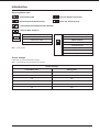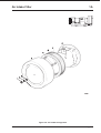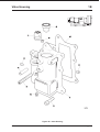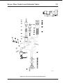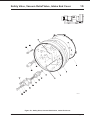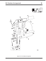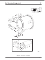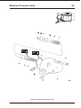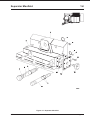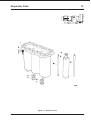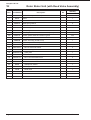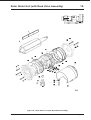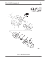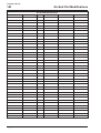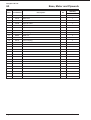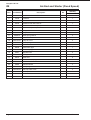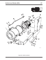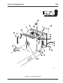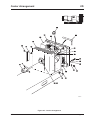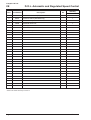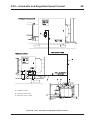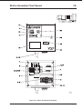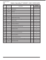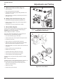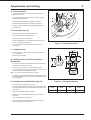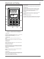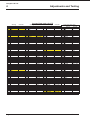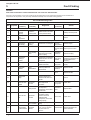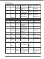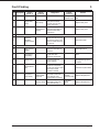
1
Parts List/Service Manual
V37 Models (PSAS)
Stationary Air Compressors
ST 16047
GB
Iss A 08/2002
This page is intentionally left blank
Introduction
Introduction
This publication contains parts lists and service information, please read it carefully before you attempt to service or carry out
adjustments on the compressor.
This publication should be used in conjunction with the User Handbook.
Note: If you need any specialist help or service, please contact your distributor or CompAir UK Ltd quoting the MODEL, TYPE and
SERIAL NUMBER.
Product development
CompAir UK Ltd adopt a policy of continual product Improvement. The information in this publication, whilst fully up to date when
issued, may be subject to change without notice.
Quality standards
CompAir UK Ltd Quality Management Systems are approved to BSENISO 9002.
Note: These instructions comply with the stipulation of European directive 98 / 37 / EEC concerning machine safety and are valid for
machines carrying the CE label.
CompAir UK Ltd
Claybrook Drive
Washford Industrial Estate
Redditch
Worcestershire
B98 ODS
England.
Web:
E-mail:
Telephone:
Fax:
www.CompAir.com
[email protected]
(01527) 525522
(01527) 521140
Model range
This handbook relates to all V37 kW 50/60 Hz compressors, model types:
V37
837PSAS08-4035V100 *
837PSAS08-4636D105 **
This publication refers to compressors with serial numbers:
* 837-000976-0210 onwards
** 837-001064-0210 onwards
Terminology:-
ST 16047A
8
=
Series
37
=
37 kW motor size
P
=
Package
S
=
Standard control
A
=
Aftercooler
S
=
Starter
08
=
8 bar delivery pressure
40, 46
=
400, 460 volt
3
=
3 phase
50 Hz, 60 Hz
5, 6
=
D&V
=
Direct On Line, Variable Speed
100
=
European specification (50 Hz)
105
=
US specification (60 Hz)
Page 1
CompAir UK Ltd
Introduction
OWNERSHIP RECORDS
Model Number:
.................................
Serial Number:
.............................
R.P.M:
.................................
kW:
.............................
Maximum Bar:
.................................
Local CompAir UK Ltd Distributor
Name:
.................................
Contact:
.............................
Address:
.................................
Telephone:
.............................
.................................
Fax:
.............................
.................................
Email:
.............................
Page 2
ST 16047A
Introduction
Service Kits
Only use genuine CompAir UK Ltd parts and approved oils. Oils must not be mixed.
Service kits contents
Item
Part Number
Quantity
Description
Chapter Location
KM85 - Maintenance Kit
1
52438
1
Air Filter 178/218/2
1A
2
59842
1
Gasket - MPV Housing
3
59946
1
Oil Filter 218/258
1F
4
59969
1
Gasket - Oil Filter Ma
1F
5
9902
1
O Ring
6
BM81
1
Bag 128/148/178/218/
7
50055
1
Gasket
1D
8
50084
1
Gasket
1B
9
50118
1
P.T.F.E. Washer
10
52109
1
O Ring
1D
11
57596
1
Vacuum Seal Valve
1D
12
58253
1
O Ring (200-136-977
1G
13
59847
1
Seal - Flow Control Valve
14
59854
1
Gasket - O.R.P. Cover
1E
15
70166
1
Blowdown Valve Filter
1C
16
9624
2
Bonded Seal - 1
17
9646
1
Copper Washer ½ B
18
9717
1
O Ring
1E
19
9790
1
O Ring
1G
20
9804
1
O Ring
21
9805
1
O Ring
22
9806
1
O Ring
1C
23
9809
1
O Ring
1C
24
RO6000-330
1
Seating Washer
25
W4-1
1
Sealing Ring
26
W7-2
1
Fibre Washer
27
ST15877
1
C4 Carton Plain
1D
KS84 - Separator Kit
1
58798
1
Gasket (Separator Ca
2
59180
3
Separator Element 128-158
1J
3
71191
1
Gasket Separator Cas
1J
4
BS84
1
Bag 128/148/178/845
5
3515C
1
Thermal Motor
6
71190
1
Gasket Separator Cover Plate
7
9605
2
Bonded Seal - 5/16
8
9609
1
Bonded Seal - 1/4
9
9619
2
Bonded Seal - 3/4
1E, 1J
10
9624
1
Bonded Seal - 1
1E, 1F
11
9748
3
O Ring
ST 16047A
1H
Page 3
CompAir UK Ltd
Introduction
Item
Part Number
Quantity
Description
Chapter Location
KS84 - Separator Kit (continued)
12
9753
2
O Ring (0166-24)
13
9758
2
O Ring (0246-24)
1H
14
9794
1
O Ring
1H
15
9795
1
O Ring (0275-30)
1H
16
9802
1
O Ring
1H
17
ST15906
1
C6 Carton Plain
KT87 - Top Up Kit
1
33111
1
Seal Assembly
1K
2
50130
1
Jubilee Clip 10.5 Diameter
1K
3
56300
1
O Ring
1K
4
58789-03
2
Stator Gasket Intake
1K
5
58789-04
2
Stator Gasket Intake
1K
6
587-03
2
Stator Gasket Drive
7
587-04
2
Stator Gasket Drive
8
72316
1
Drive Element
9
72832
1
Pressure Gauge 63 mm
10
73557
1
Gasket I.E.C.8 Series
11
9894
1
O Ring
12
BT8
1
Bag 128/148/178/218/
13
1846-P
1
O.R.V. Filter Assembly
14
1846
1
O.R.V. Filter Assembly
15
1728
1
O.R.V. Filter Nut
16
3416
1
Oil Return Valve Filter
17
58117
1
Sight Level Glass
1E
18
58426
1
Sight Glass Clip
1E
19
9605
10
Bonded Seal - 5/16
1K
20
9607
8
Bonded Seal - .40
1K
21
9613
2
Bonded Seal - 3/8
22
9616
1
Bonded Seal - 1/2
1D
23
9619
1
Bonded Seal - 3/4
1E
24
9624
3
Bonded Seal - 1
25
9703
1
O Ring
26
9708
1
O Ring
27
9754
1
O Ring
28
9792
2
O Ring
29
9794
2
O Ring
1F
30
9811
1
O Ring
1K
31
9896
2
O Ring
1K
32
ST15877
1
C4 Carton Plain
1K
1K
1G
1E, 1F
1E
Note: Spare parts to be stored in original packaging and in a dry environment. Repaired or replacement units should be protected
against corrosion and mechanical damage during storage.
Page 4
ST 16047A
Introduction
Key to symbols used
15
Nm
22mm
Torque Setting Nm.
Silco
660
Grease Required (Specification)
577
Loctite Required and Specification Number
5mm
Spanner Required (mm) A/F
Allen key Required (mm)
Lubricate With Sump Oil
Recommended Oils
Recommended Grease
Fluid Force Clear
Silkolene 660
Fluid Force 2000
Motor Grease
Fluid Force HPO
Esso Unirex N3
Shell Albida R2
Shell Nerita HV
Note: Do not mix oils.
SKF LGHQ3
Castrol Optimol PD2
Torque settings
Listed below are recommended torque settings.
Note: Torque settings must be applied when indicated.
Torque Settings
ST 16047A
Thread Size (mm)
Setting (Nm)
6
15
8
35
10
60
12
95
16
160
42
400
Page 5
CompAir UK Ltd
Introduction
This page is intentionally left blank
Page 6
ST 16047A
Contents
Parts List and Service Manual
Contents
Chapter
Page
Air-End . . . . . . . . . . . . . . . . . . . . . . . . . . . . . . . . . . . . . . . . . . . . . . . . . . . . . . . . . . . . . 1 . . . . . . . . . . . . 9
Main Assembly . . . . . . . . . . . . . . . . . . . . . . . . . . . . . . . . . . . . . . . . . . . . . . . . . . . . . . . 2 . . . . . . . . . . . 37
Starter Assemblies . . . . . . . . . . . . . . . . . . . . . . . . . . . . . . . . . . . . . . . . . . . . . . . . . . . . 3 . . . . . . . . . . . 51
Adjustments and Testing . . . . . . . . . . . . . . . . . . . . . . . . . . . . . . . . . . . . . . . . . . . . . . . . 4 . . . . . . . . . . . 59
Fault Finding . . . . . . . . . . . . . . . . . . . . . . . . . . . . . . . . . . . . . . . . . . . . . . . . . . . . . . . . . 5 . . . . . . . . . . . 65
ST 16047A
Page 7
CompAir UK Ltd
This page is intentionally left blank
Page 8
ST 16047A
Compressor Air-End
1
Chapter 1
Contents
Section
Page
Air Intake Filter . . . . . . . . . . . . . . . . . . . . . . . . . . . . . . . . . . . . . . . . . . . . . . . . . . . . . . . A . . . . . . . . . . . 10
Valve Housing . . . . . . . . . . . . . . . . . . . . . . . . . . . . . . . . . . . . . . . . . . . . . . . . . . . . . . . . B . . . . . . . . . . . 12
Servo, Flow Control and Unloader Valve . . . . . . . . . . . . . . . . . . . . . . . . . . . . . . . . . . . C . . . . . . . . . . . 14
Safety Valve, Vacuum Relief Valve, Intake End Cover . . . . . . . . . . . . . . . . . . . . . . . . . D . . . . . . . . . . . 18
Oil Chamber Arrangement . . . . . . . . . . . . . . . . . . . . . . . . . . . . . . . . . . . . . . . . . . . . . . E . . . . . . . . . . . 20
Bell Housing Arrangement . . . . . . . . . . . . . . . . . . . . . . . . . . . . . . . . . . . . . . . . . . . . . . F . . . . . . . . . . . 22
Minimum Pressure Valve . . . . . . . . . . . . . . . . . . . . . . . . . . . . . . . . . . . . . . . . . . . . . . . G . . . . . . . . . . . 24
Separator Manifold . . . . . . . . . . . . . . . . . . . . . . . . . . . . . . . . . . . . . . . . . . . . . . . . . . . . H . . . . . . . . . . . 26
Separator Case . . . . . . . . . . . . . . . . . . . . . . . . . . . . . . . . . . . . . . . . . . . . . . . . . . . . . . . J . . . . . . . . . . . 28
Rotor Stator Unit (with Oil Relief Valve Assembly) . . . . . . . . . . . . . . . . . . . . . . . . . . . . K . . . . . . . . . . . 30
Drive End Arrangement. . . . . . . . . . . . . . . . . . . . . . . . . . . . . . . . . . . . . . . . . . . . . . . . . L . . . . . . . . . . . 34
Air-End Part Modifications . . . . . . . . . . . . . . . . . . . . . . . . . . . . . . . . . . . . . . . . . . . . . . M . . . . . . . . . . . 36
ST 16047A
Page 9
CompAir UK Ltd
1A
Air Intake Filter
Item
Part Number
1
73147
2
MN1710
3
Description
Kit
Quantity
V37
Nut protection cap
1
M10 Nylock nut
1
W7-2
Fibre washer
1
4
52437
Filter cover
1
5
59604
Air filter cover spacer
1
6
MW10
M10 washer
1
7
52438
Air filter
8
58856
Intake filter support
Page 10
KM85
1
1
ST 16047A
Air Intake Filter
1A
Figure 1A - Air Intake Arrangement
ST 16047A
Page 11
CompAir UK Ltd
1B
Item
Valve Housing
Part Number
Description
33818
Unloader housing assy
1
72334
Unloader housing
2
50707
3
MS706-20
4
Kit
Quantity
V37
1
Insert (with item 1)
1
M6 x 20 socket head screw
7
71791
Flow control sleeve
1
5
TP1
Taper plug 1/8 BSP
2
6
52443
Tension pin
1
7
58865
M10 x 90 stud
1
8
50084
Gasket
Page 12
KM85
1
ST 16047A
Valve Housing
1B
Figure 1B - Valve Housing
ST 16047A
Page 13
CompAir UK Ltd
1C
Item
Servo, Flow Control and Unloader Valve
Part Number
33713
1
MG708-30
2
Description
Kit
Servo valve assembly
Quantity
V37
1
M8 x 30 socket grub screw
1
MN108
M8 nut
1
3
71807
Servo valve end cap
1
4
50110
Spring support
1
5
RO6000-115
Servo spring
1
6
50105
Servo piston
1
7
59912
O ring
1
33003
Servo sleeve assembly
1
8
59597
Servo sleeve
1
9
3291
Tension pin
1
10
MG1706-6
11
72197
Plug non return valve
1
12
70622
Non return valve spring
1
13
59650-04
Stainless steel ball
1
14
58962
Equal elbow M/F 1/8 BSP
1
15
59014
Filter shroud
1
16
70166
Blowdown valve filter
33817
Flow control valve assembly
M6 x 6 socket set screw tuflock
KM85
1
1
17
ST10024
18
72189
Flow control valve plug
1
19
9617
Bonded seal 5/8
1
20
50116
Flow control valve piston
1
21
50115
Spring
1
Page 14
Locking wire
2
A/R
ST 16047A
Servo, Flow Control and Unloader Valve
1C
1
22
2
23
3
24
17
4
25
18
5
19
26
20
6
21
7
11
12
8
13
9
14
10
15
27
16
28
29
30
31
32
33
34
35
36
435A330
Figure 1C - Servo, Flow Control and Unloader Valve
ST 16047A
Page 15
CompAir UK Ltd
1C
Item
Servo, Flow Control and Unloader Valve
Part Number
33814
Description
Kit
Unloader valve assembly
Quantity
V37
1
22
MCI50
Circlip internal
1
23
50113
Unloader valve cap
1
24
9806
O ring
25
50035A
26
KM85
1
Unloader valve piston (letter stamped on piston)
1
50243
Unloader valve spring
1
32334
Unloader stem assembly
1
27
57175
Valve stem
1
28
57176
Valve head
1
29
56950
Tension pin
1
30
50118
P.T.F.E. washer
1
31
50106
Front washer
1
32
MW8
M8 washer heavy gauge
1
33
MN1708
M8 nylock nut
1
34
9809
O ring
35
50036
Unloader valve seat
1
36
MS706-16-741
M6 x 16 socket cap screw
2
Page 16
KM85
1
ST 16047A
Servo, Flow Control and Unloader Valve
1C
1
22
2
23
3
24
17
4
25
18
5
19
26
20
6
21
7
11
12
8
13
9
14
10
15
27
16
28
29
30
31
32
33
34
35
36
435A330
Figure 1C - Servo, Flow Control and Unloader Valve
ST 16047A
Page 17
CompAir UK Ltd
1D
Item
Safety Valve, Vacuum Relief Valve, Intake End Cover
Part Number
32775-02
1
58740-02
2
52403
3
RO20000-80
4
Description
Kit
Intake end cover assembly
Quantity
V37
1
Intake end cover
1
Bearing
1
Bronze bush (part of item 1)
1
TP1
Taper plug 1/8 BSP
6
5
TP2
Taper socket ¼ BSP
1
6
73557
Gasket
1
7
9902
O ring
1
30011
Vacuum relief valve assembly
1
8
52109
O ring
9
RO20000-225
Valve
10
57596
11
RO20000-79
Spring
12
50055
Gasket
13
50008
Vacuum relief valve cap
1
14
W4-1
Sealing ring
1
15
MN206
M6 lock-nut
1
16
MS106-35
M6 x 35 hex head screw
1
17
MS706-16
M6 x 16 socket head screw
2
18
53399
Safety valve (150 PSI)
19
9616
Bonded seal 1/2
20
MS708-30
21
9605
Page 18
Vacuum valve seal
KM85
1
KM85
1
1
KM85
1
1
KT87
M8 x 30 socket head screw
Bonded seal 5/16
1
1
8
KT87
8
ST 16047A
Safety Valve, Vacuum Relief Valve, Intake End Cover
1D
2
5
21
20
4
6
19
18
1
8
17
9
7
3
10
11
12
13
14
15
16
435A331
Figure 1D - Safety Valve, Vacuum Relief Valve, Intake End Cover
ST 16047A
Page 19
CompAir UK Ltd
1E
Item
Oil Chamber Arrangement
Part Number
33965
1
72920
2
MHC16-24
3
Description
Kit
Oil chamber assembly
Quantity
V37
1
Oil chamber
1
M16 x 1.5D helicoil
1
59425-04
Taper plug brass ½ BSP
1
4
MHC8-16
M8 x 2D helicoil
8
5
3554
Drain plug 1 BSP
3
6
9624
Bonded seal
7
53452
Auxiliary baffle
1
8
52613
Self tapping screw
4
9
MS706-20
10
KT87
3
M6 x 20 socket head screw
2
50044
O.R.P. cover plate
1
11
59854
Gasket O.R.P. Cover plate
12
71241
Oil restrictor plug
2
13
72832
Pressure gauge 63 mm
1
14
72822
Nameplate
1
33145
Sight glass assembly
1
15
59855
Sight glass housing
1
16
9754
O ring
1
17
58117
Sight level glass
KT87
1
18
58426
Sight glass clip
KT87
1
19
50764
Spring
20
9717
O ring
21
30152
Servo filter assembly
22
9619
Bonded seal 3/4
23
1668
Drain plug ¾ BSP
1
24
72360
Filler plug
1
25
9624
Bonded seal 1
26
72366
Symbolic label
Page 20
KM85
1
1
KT87
1
1
KT87
KT87
1
2
1
ST 16047A
Oil Chamber Arrangement
1E
Figure 1E - Oil Chamber Arrangement
ST 16047A
Page 21
CompAir UK Ltd
1F
Bell Housing Arrangement
Part Number
1
70105
Bell housing
1
2
52030
Eye bolt
1
3
56447
Cover plate
1
4
MWG-6
M6 spring washer
2
5
MS106-12
M6 x 12 hex head screw
2
6
MS712-60
M12 x 60 socket head screw
6
7
MWG-12
M12 spring washer
6
Thermal bypass assembly
1
33094
Description
Kit
Quantity
Item
V37
8
53191
End cap
1
9
9624
Bonded seal 1" BSP
10
MCI-22
Circlip 22 mm internal
1
30661A
Bypass piston assembly
1
KT87
1
11
3515C
Thermal motor
1
12
74141
Piston
1
13
52487
14
9794
17
MS710-30
18
MWG10
19
20
Spring
O ring
1
KS84
2
M10 x 30 socket head screw
2
M10 spring washer
2
57996
Drain plug 3/8"
1
9613
Bonded seal 3/8"
1
33288
Oil filter manifold assembly
1
21
59969
Gasket
22
70570
Oil filter manifold
1
23
70576
Stud
2
24
70575
Stud
1
25
9604
Bonded seal 1/4"
3
26
70578
Cap nut
3
27
57816
Threaded insert
1
28
MWG-8
M8 spring washer
1
29
MS108-25
M8 x 25 hex head screw
1
30
59946
31
32
Page 22
Oil filter
RO10000-331 Grommet
32931
Thermistor cable assembly
KM85
KM85
1
1
1
1
ST 16047A
Bell Housing Arrangement
1F
Figure 1F - Bell Housing Arrangement
ST 16047A
Page 23
CompAir UK Ltd
1G
Minimum Pressure Valve
Part Number
1
58244
2
MS708-55
3
1846
Oil return valve assembly
KT87
1
4
58253
O ring
KM85
1
5
59097
MPV spring
6
9790
O ring
7
50078
MPV piston
1
8
59098
MPV return spring
1
9
50072
Shim
3
10
RO6000-331
Facing and stem
1
11
RO6000-330
Seating washer
12
RO6000-329
Retaining washer
1
13
UCN 504
Nut ¼ UNC Philidas
1
14
73212
Stud coupling ¼ x 4
1
Page 24
Description
Kit
Quantity
Item
V37
MPV housing
1
M8 x 55 socket head screw
4
1
KM85
KM85
1
1
ST 16047A
Minimum Pressure Valve
1G
Figure 1G - Minimum Pressure Valve
ST 16047A
Page 25
CompAir UK Ltd
1H
Separator Manifold
Description
Kit
Quantity
Item
Part Number
1
70045
2
MS710-50
3
9748
O ring
KS84
3
4
9802
O ring
KS84
1
5
9794
O ring
KS84
1
6
58607
Advel seal 5 mm diameter
1
7
58796
Separator bolt (air)
1
8a
70538-01
Shim separator bolt 0.125
A/R
8b
70538-02
Shim separator bolt 0.190
A/R
8c
70538-03
Shim separator bolt 0.317
A/R
9
9795
O ring
10
70051
Separator bolt (oil)
11
9758
O ring
32972
Blanking plate assembly
V37
Separator manifold
1
M10 x 50 socket head screw
2
KS84
1
1
KS84
2
1
12
71190
Gasket separator cover plate
1
13
71584
Blanking plate
1
14
59244
Dial thermometer
1
15
MS706-25
M6 x 25 socket head screw
8
Page 26
ST 16047A
Separator Manifold
1H
Figure 1H - Separator Manifold
ST 16047A
Page 27
CompAir UK Ltd
1J
Separator Case
Part Number
1
71191
Gasket
2
70046
Separator case
1
3
70071
M8 washer
16
4
MWG8
M8 spring washer
16
5
MS708-35
M8 x 35 socket head screw
16
6
9619
Bonded seal 3/4"
7
1668
Drain plug ¾" BSP
8
59180
Separator element
9
9799
O ring (part of item 8)
3
10
58801
Separator element stud
3
11
59551
Oil scavenge pipe
1
Page 28
Description
Kit
Quantity
Item
KS84
KS84
V37
1
2
2
KS84
3
ST 16047A
Separator Case
1J
Figure 1J - Separator Case
ST 16047A
Page 29
CompAir UK Ltd
1K
Rotor Stator Unit (with Reed Valve Assembly)
Part Number
1
58759
Drilled blade (50 and 60 Hz)
24
4
58754
Rotor
1
5
MS710-35
M10 x 35 socket head screw
4
6
MWG10
M10 spring washer
5
7
MS710-90
M10 x 90 socket head screw
1
8
MS708-80
M8 x 80 cap head screw
2
9
MWG8
M8 spring washer
2
10a
58789-03
Stator gasket intake end 0.05 mm blue (trans)
A/R
10b
58789-04
Stator gasket intake end 0.08 mm green
A/R
11
9902
34164-04
Description
O ring
Stator assembly (83708 60 Hz)
Kit
Quantity
Item
KT87
V37
1
1
12
73426-04
Stator (837K08 60 Hz)
1
13
HD75120E5
Drive rivet 5/16 x No.6
6
14
MG1706-6
M6 x 6 socket set tuflock
2
15
70219
Valve seating bush
1
16
RO20000-105
Valve plate
1
17
57492
Valve washer
1
18
MS705-10
M5 x 10 socket head screw
2
34271
19
MS705-10
20
Reed valve assembly
6
M5 x 10 socket head screw
1
MWI5
Shakeproof washer
1
21
73700
Valve guard
1
22
73198
Reed valve
1
Page 30
ST 16047A
Rotor Stator Unit (with Reed Valve Assembly)
1K
Figure 1K - Rotor Stator Unit (with Reed Valve Assembly)
ST 16047A
Page 31
CompAir UK Ltd
1K
Rotor Stator Unit (with Reed Valve Assembly)
Part Number
23a
58790-03
Stator gasket intake end 0.05 mm (trans) blue
KT87
A/R
23b
58790-04
Stator gasket intake end 0.08 mm green
KT87
A/R
23c
58789-06
Stator shim - smoke blue 0.13
A/R
23d
58789-05
Stator shim - amber 0.10
A/R
23e
58790-05
Stator shim - amber 0.10
A/R
24
9896
O ring
KT87
2
25
9894
O ring
KT87
1
26
9607
Bonded seal 0.4
KT87
6
27
MS710-35
M10 x 35 socket head screw
5
28
MS708-35
M8 x 35 socket head screw
2
29
9605
Bonded seal 5/16
KT87
2
30
50130
Jubilee clip 10.5 diameter
KT87
1
31
72136
Cowl
1
32
MS106-12
M6 x hex head screw
6
33
MWG6
M6 spring washer
4
34
MW6
M6 washer
6
Page 32
Description
Kit
Quantity
Item
V37
ST 16047A
Rotor Stator Unit (with Reed Valve Assembly)
1K
Figure 1K - Rotor Stator Unit (with Reed Valve Assembly)
ST 16047A
Page 33
CompAir UK Ltd
1L
Drive End Arrangement
Description
Kit
Quantity
Item
Part Number
1
50050
Woodruff key
1
32776
Drive end cover assembly
1
V37
2
58727
Drive end cover
1
3
52403
Bearing
1
4
59425-02
Taper plug brass ¼ BSP
1
5
MS705-16
6a
M5 x 12 socket head screw 12 long
2
MW5
M5 washer, plain
2
6b
MWG5
M5 spring washer
2
6c
MN105
Nut, hex M5
2
7
33348a
Terminal block assembly
1
7a
70844
Terminal block
7b
70857
Terminal block
8
9607
Bonded seal 0.4
9
70154
Thermistor probe 110°C
1
10a
33110
Oil seal assembly (original)
1
10b
33111
Oil seal (replacement)
KT87
1
11
9811
O ring
KT87
1
12
MWG6
13
KT87
M6 spring washer
6
2
MS706-16-741 M6 x 16 socket cap screw
2
14
72314
Drive coupling compressor
1
15
MW30
M30 washer
1
16
52421
M30 dri-loc nut
1
17
72316
Drive element
18
MG710-25
M10 x 25 grub screw
2
19
72315
Drive coupling motor
1
Page 34
KT87
1
ST 16047A
Drive End Arrangement
1L
Figure 1L - Drive End Arrangement
ST 16047A
Page 35
CompAir UK Ltd
1M
Air-End Part Modifications
Air-End Part Modifications
Serial No. Prefix
Page 36
Compressor(s)
Ref
New Part(s)
Old Part(s)
Service Bulletin
ST 16047A
Main Assembly
2
Chapter 2
Contents
Section
Page
Base, Motor and Pipework . . . . . . . . . . . . . . . . . . . . . . . . . . . . . . . . . . . . . . . . . . . . . . A . . . . . . . . . . 38
Air-End and Starter (Fixed Speed) . . . . . . . . . . . . . . . . . . . . . . . . . . . . . . . . . . . . . . . . B . . . . . . . . . . . 40
Air-End and Starter (RS). . . . . . . . . . . . . . . . . . . . . . . . . . . . . . . . . . . . . . . . . . . . . . . . C . . . . . . . . . . . 42
Cooler Arrangement . . . . . . . . . . . . . . . . . . . . . . . . . . . . . . . . . . . . . . . . . . . . . . . . . . . D . . . . . . . . . . . 44
D.O.L. Automatic and Regulated Speed Control . . . . . . . . . . . . . . . . . . . . . . . . . . . . . . E . . . . . . . . . . . 48
Main Assembly Part Modifications . . . . . . . . . . . . . . . . . . . . . . . . . . . . . . . . . . . . . . . . F . . . . . . . . . . . 50
ST 16047A
Page 37
CompAir UK Ltd
2A
Base, Motor and Pipework
Item
Part Number
1
75083-10
2
Description
Kit
Quantity
V37
Motor 37 kW 400 V 50 Hz
1
75104
Base V37
1
3
75105
Motor stand V37
2
4
75158
Pipe oil outlet
1
5
75159
Pipe oil return
1
6
MS116-55
M16 x 55 hex hd screw
4
7
MW16
M16 washer
8
8
MWG 16
M16 spring washer
8
9
MN16
M16 nut
4
10
MS116-40
M16 x 40 hex hd screw
4
14
52744
Stud coupling
4
15
9624
Bonded seal
4
Page 38
ST 16047A
Base, Motor and Pipework
2A
1
6
7
8
9
15
14
15
14
3
5
5
4
7
14, 15
8
9
14
15
2
435A356
Figure 2A - Base, Motor and Pipework
ST 16047A
Page 39
CompAir UK Ltd
2B
Air-End and Starter (Fixed Speed)
Item
Part Number
1
83708-005
2
Description
Kit
Quantity
V37
37 kW metric 60 Hz air end
1
74445
Label kit
1
3
75173
Bracket
1
4
34723
Starter 37 kW 460 V 60 Hz
1
4a
34728
Starter 37 kW 400 V (RS)
1
5
75174
Front cover (starter)
1
6
75154
Support
1
7
MS712-25
Cap hd screw
2
8
MWG12
M12 spring washer
2
9
MW12
M12 flat washer
2
10
MS710-20
Cap hd screw
2
11
MWG10
M10 spring washer
2
12
MW10
M10 flat washer
2
13
59292
Aftercooler pipe
1
14
53461
Stud coupling
2
15
9624
Bonded seal
2
16
53344
Lifting bracket
2
17
52573
M16 stud
8
18
MWG16
M16 washer, spring
8
19
MN116
M16 hex nut
8
20
MW8
M8 flat washer
4
21
MWG8
M8 spring washer
4
22
MS108-20
M8 cap head screw
4
23
57375-01
Self tap screw
6
Page 40
ST 16047A
Air-End and Starter (Fixed Speed)
14
2B
15
18
19
17
24
13
20
3
4
16
14
15
2
r
pAi
Com
1
23
5
22
21
20
11, 12
10
7
6
8, 9
435A354
Figure 2B - Air-End and Starter (Fixed Speed)
ST 16047A
Page 41
CompAir UK Ltd
2C
Air-End and Starter (RS)
Part Number
16
75152
Support RS
1
17
75153
Tie brackets (RS)
1
18
MW12
M12 plain washer
8
19
MWG 12
M12 spring washer
8
20
MS112-25
M12 x 25 hex hd screw
8
21
MN112
M12 hex nut
2
22
MWG8
M8 spring washer
2
23
MN108
M8 hex nut
2
Page 42
Description
Kit
Quantity
Item
V37
ST 16047A
Air-End and Starter (RS)
2C
14
15
4a
18
19
23 22
13
14
17
15
20
2
19
r
pAi
Com
1
18
21
16
11, 12
10
7
6
8, 9
18
19
20
435A359
Figure 2B - Air-End and Starter
ST 16047A
Page 43
CompAir UK Ltd
2D
Cooler Arrangement
Item
Part Number
2
MS112-35
3
MW12
4
Description
Kit
Quantity
V37
M12 x 35 hex head screw
4
M12 washer
8
58837-01
Radiator duct spacer 5 mm thick
2
5
MWG12
M12 spring washer
4
6
MN12
M12 nut
4
10
73070
Fan coupling
1
11
MG710-10
M10 x 10 Skt grub screw
2
14
53461
Stud coupling G1 x 25 mm
2
16
57375-01
Self tapping screw
6
17
71027
Aperture cover
1
18
73583
Spire nut
6
19
75161
Fan guard
1
20
75160
Cooler duct
1
21
72759
Combination cooler
1
Page 44
ST 16047A
Cooler Arrangement
2D
23
21
20
35
22
19
16
17
18
24
25
26
27
28
10
11
29
31
32
18
30
16
33, 34
435A355
Figure 2C - Cooler Arrangement
ST 16047A
Page 45
CompAir UK Ltd
2D
Cooler Arrangement
Part Number
22
75183
Fan
1
23
70943
Fan retainer
1
24
MS708-30
M8 x 30 cap head screw
4
25
MWG8
M8 spring washer
4
26
MW8
M8 spring washer
4
27
MS708-20
M8 x 20 socket head screw
3
28
MWG8
M8 spring washer
3
29
MW8
M8 washer
3
30
1668
¾" BSP drain plug
1
31
9619
Bonded seal 3/4"
1
32
72997
U type retaining nut
3
33
73258
Fan guard extension
1
34
70686
Pop rivet 1/8" x 3/8" l
3
35
72191
Seal strip
Page 46
Description
Kit
Quantity
Item
V37
1.6m
ST 16047A
Cooler Arrangement
2D
23
21
20
35
22
19
16
17
18
24
25
26
27
28
10
11
29
31
32
18
30
16
33, 34
435A355
Figure 2C - Cooler Arrangement
ST 16047A
Page 47
CompAir UK Ltd
2E
D.O.L. Automatic and Regulated Speed Control
Description
Part Number
1
72118
Pressure transducer (RS)
1*
2
53287
Pressure switch (Standard only)
1
3
ST214671
4
74866
Solenoid valve N.O.
1
4a
70793
Hex nipple
1
4b
73283
Elbow
1
5
73212
RP1/4-6 mm push-in
Tube 6 mm nylon
Kit
Quantity
Item
V37
A/R
A/R
* Refer to RS Starter Assembly in Section 3.
Page 48
ST 16047A
D.O.L. Automatic and Regulated Speed Control
2E
PRESSURE TRANSDUCER
1
B
V37 RS
REGULATED SPEED
PRESSURE SWITCH
3
B
V37
B
3
D.O.L. AUTOMATIC
CONTROL
4
A
5
A = Separator Pressure
B = Delivery Pressure in MPV
C = Blow-down, return to intake
C
C
435A343
Figure 2D - D.O.L. Automatic and Regulated Speed Control
ST 16047A
Page 49
CompAir UK Ltd
2F
Main Assembly Part Modifications
Main Assembly Part Modifications
Serial No. Prefix
Page 50
Compressor(s)
Ref
New Part(s)
Old Part(s)
Service Bulletin
ST 16047A
Starter Assemblies
3
Chapter 3
Contents
Section
Page
Starter Assembly Fixed Speed . . . . . . . . . . . . . . . . . . . . . . . . . . . . . . . . . . . . . . . . . . . A . . . . . . . . . . 52
Starter Assembly 37 kW 400 V/460 V 50/60 Hz RS . . . . . . . . . . . . . . . . . . . . . . . . . . . B . . . . . . . . . . . 54
Starter Assembly Part Modifications . . . . . . . . . . . . . . . . . . . . . . . . . . . . . . . . . . . . . . . C . . . . . . . . . . . 58
ST 16047A
Page 51
CompAir UK Ltd
3A
Item
Starter Assembly Fixed Speed
Part Number
34728
Description
Kit
Quantity
V37
Starter assembly
1
-
Enclosure
1
2
74906
Contactor
1
3
74907
Thermal overload (208-230V)
1
4
74232
Circuit breaker
1
5
56121
Timer
1
6
56122
Timer
1
7
53494
Timer base
2
8
56105
Retaining clips (pair)
2
9
59344
OTC board
1
10
74024
Terminal double stack
6
11
74025
End section
2
12
-
Profile rail
13
-
Earth terminal
2
14
-
End section
2
15
-
Trunking
16
-
Transformer
1
17
74027
Fuse 1.6A (T) IEC127 F2F
2
18
74067
Knob operator (auto)
1
19
74068
Indicator lamp (reset)
1
20
72708
Push button (start)
1
21
74080
Hours counter
1
22
74249
Emergency stop push button
1
23
-
Rating label
1
24
74908
Terminal
3
25
74909
Earth terminal
1
26
75150
Facia label
1
27
75151
Label.Model logo (modify)
1
28
75171
Label.circuit diagram
1
29
-
End section
2
30
-
Motor conduit
1
31
-
Straight fitting
2
32
-
Locknut
1
Page 52
A/R
A/R
ST 16047A
Starter Assembly Fixed Speed
3A
21
18
22
h
20
0
r
I
19
26
23
V37
28
27
30 - 32
1
16, 17
2
L1 L2 L3
24, 25, 29
Q1F
4
L1 L2 L3
*** *
3
15
W1 V1 U1
** *
9
5-8
K2T
K3T
10 - 14
435A344
34728-A
Figure 3A - Starter Assembly Fixed Speed
ST 16047A
Page 53
CompAir UK Ltd
3B
Item
Starter Assembly 37 kW 400 V / 460 V 50/60 Hz RS
Part Number
Description
Kit
Quantity
V37
34723
Starter assembly
1
75141
Enclosure (modified)
1
2
74906
Contactor
1
3
74371
Circuit breaker
1
4
56122
Relay (K2A)
1
5
74820
Timer (K3T)
1
6
-
Timer/relay base
2
7
56105
Retaining clips (pair)
2
8
59344
OTC board
1
9
74024
Terminal double stack
10
10
74025
End section
2
11
-
Profle rail
12
-
Earth terminal
13
-
Trunking
14
75101
Inverter 37 kW 400-480 Vac
1
15
74026
Transformer 4AM13496-DEC80-1FA0
1
16
-
Fuse 1.6A (T) IEC127 F2F
2
17
-
Chassis plate
1
18
74067
Knob operator (auto)
1
19
74068
Indicator lamp (reset)
1
20
72708
Push button (start)
1
21
50432
Hours counter
1
22
74249
Emergency stop push button
1
23
-
Rating label
1
24
74043
Power outlet socket
1
25
-
Terminal, P1.P+ (blue-35 mm)
2
26
74909
Earth terminal
1
27
75150
Facia label
1
28
75107
Label.circuit diagram
1
29
74908
Terminal, L1,L2 L3
1
30
75146
Filter grid c/w filter
2
31
75102
EMC filter
1
Page 54
A/R
2
A/R
ST 16047A
Starter Assembly 37 kW 400 V / 460 V 50/60 Hz RS
21
18
22
3B
27
35 - 37
30
h
20
0
r
I
28
19
58
30, 34
47 - 50
V37 RS
56
38, 39
45, 46
U1
V1
W1
48
49
R2F
Y10
42 - 44
47 - 50
435A345
34723-A
Figure 3B - Starter Assembly 37 kW 400 V / 460 V 50/60 Hz RS
ST 16047A
Page 55
CompAir UK Ltd
3B
Starter Assembly 37 kW 400 V / 460 V 50/60 Hz RS
Part Number
32
75103
DC choke
1
33
74864
End bracket
1
34
75149
Filtering panel
1
35
74050
Fan unit
1
36
74051
Finger guard (external)
1
37
74052
Finger guard (internal)
1
38
75142
Gland plate
1
39
75143
Gasket for item 38
1
40
75144
Baffle (inverter cooling)
1
41
75145
Foam baffle (inverter cooling)
1
42
-
Motor conduit
1
43
-
Straight fitting
2
44
-
Locknut
1
45
72118
Pressure transducer
1
46
73245
Female bulkhead connector, BSP
1
47
-
M8 x 25 long hex head set screw
6
48
-
M8 hex locknut
6
49
-
M8 spring washer
6
50
-
M8 washer
8
51
52057
Lifting bracket
2
52
-
M12 x 30 long cap head screw
2
53
-
M12 hex nut
2
54
-
M12 spring washer
2
55
-
M12 washer
4
56
75151
Label.model logo V37 RS
4
57
-
Blind grommet (not shown on drawing)
2
58
-
Perspex window, inverter read-out
1
59
75051
End section (earth)
1
60
-
End section 35 mm terminals
2
Page 56
Description
Kit
Quantity
Item
V37
ST 16047A
Starter Assembly 37 kW 400 V / 460 V 50/60 Hz RS
3B
40
1
32
15, 16
2
3
17
31
25, 26, 29,
33, 60
L1 L2 L3
P+ P1
L1 L2 L3
P+ P1
13
8
14
9 - 12, 59
23
4-7
51 - 55
41
435A346
34723-A
Figure 3B - Starter Assembly 37 kW 400 V / 460 V 50/60 Hz RS
ST 16047A
Page 57
CompAir UK Ltd
3C
Starter Assembly Part Modifications
Starter Assembly Part Modifications
Serial No. Prefix
Page 58
Compressor(s)
Ref
New Part(s)
Old Part(s)
Service Bulletin
ST 16047A
Adjustments and Testing
4
Chapter 4
Contents
Section
Page
Minimum Pressure Valve . . . . . . . . . . . . . . . . . . . . . . . . . . . . . . . . . . . . . . . . . . . . . . . A . . . . . . . . . . . 62
Safety Valve Lift Pressure . . . . . . . . . . . . . . . . . . . . . . . . . . . . . . . . . . . . . . . . . . . . . . . B . . . . . . . . . . . 62
Servo Valve . . . . . . . . . . . . . . . . . . . . . . . . . . . . . . . . . . . . . . . . . . . . . . . . . . . . . . . . . . C . . . . . . . . . . . 62
Oil Temperature . . . . . . . . . . . . . . . . . . . . . . . . . . . . . . . . . . . . . . . . . . . . . . . . . . . . . . D . . . . . . . . . . . 63
Air Output . . . . . . . . . . . . . . . . . . . . . . . . . . . . . . . . . . . . . . . . . . . . . . . . . . . . . . . . . . . E . . . . . . . . . . . 63
Leakage Check . . . . . . . . . . . . . . . . . . . . . . . . . . . . . . . . . . . . . . . . . . . . . . . . . . . . . . . F . . . . . . . . . . . 63
Setting the Run-On Timer . . . . . . . . . . . . . . . . . . . . . . . . . . . . . . . . . . . . . . . . . . . . . . . G . . . . . . . . . . . 63
Testing Vacuum Relief Valve. . . . . . . . . . . . . . . . . . . . . . . . . . . . . . . . . . . . . . . . . . . . . H . . . . . . . . . . . 63
RS Speed Compressors . . . . . . . . . . . . . . . . . . . . . . . . . . . . . . . . . . . . . . . . . . . . . . . . I . . . . . . . . . . . 64
ST 16047A
Page 59
CompAir UK Ltd
4
Adjustments and Testing
A - Minimum Pressure Valve (Fig 4.1)
•
Start compressor.
•
Open outlet valve fully to atmosphere.
•
Check the lowest pressure gauge reading obtainable. This
should be 5.2 - 5.5 bar.
•
Adjust pressure by increasing or decreasing the number of
shims (B) in valve.
B
A
B - Safety Valve Lift Pressure (Fig. 4.1)
•
Close outlet valve. Start compressor (continuous run).
•
Screw in servo until safety valve (A) lifts. Gauge pressure
should be 10 bar.
•
If lift pressure is incorrect, replace valve complete.
C - Servo Valve (Fig 4.2)
435A347
The servo valve controls pressure at a pre-set factory setting
when there is no demand for air. The specified setting is a
maximum and must not be exceeded.
Figure 4.1 - Minimum Pressure Valve and
Safety Valve Lift Pressure
Factory setting 8 bar models :- 8.5 /9.0 bar
If the servo needs minor adjustments or a lower pressure is
required then carry out the following procedure:
•
Turn mains electrical supply on at isolator.
•
Close air outlet valve to air-line system and open test valve.
•
Fit silencer to test valve.
•
Select continuous run mode and start compressor.
•
Adjust test valve so that the air-end pressure gauge reads
approx 8.0 bar and allow compressor to warm up.
•
After approximately 10 minutes, close the test valve and stop
compressor.
•
Remove air filter cover (A) and air filter (B).
•
Release servo lock-nut (D).
•
Check test valve and air outlet valve are closed.
•
Start compressor and allow pressure to stabilise.
•
Check compressor pressure gauge reading:
E
D
If reading too low, turn grub-screw (E) clockwise to increase
pressure.
C
Note: Must not exceed 9.0 bar.
B
If reading too high or a lower operating pressure is required, turn
grub-screw (B) counter-clockwise to decrease pressure.
•
Open and close the test valve and check that pressure
stabilises at required setting.
•
Secure lock-nut (D).
•
Refit air filter (A) and cover (B).
Page 60
A
435A348
Figure 4.2 - Servo Valve
ST 16047A
Adjustments and Testing
4
D - Oil Temperature
•
Introduce a small amount of oil and a thermometer into the
thermometer pocket.
•
Allow compressor to run for 30 minutes in order to attain its
normal working temperature.
1
•
Average running temperature should be 85°C approx.
2
•
Refit fiIIer plug and its seal when testing is completed.
•
Average running temperature should be approximately 50°C
above ambient.
E - Air Output (Fig 4.4)
•
Screw test nozzle into compressor outlet valve.
•
Close outlet valve and start compressor.
•
Open outlet valve fully to atmosphere.
•
Pressure indicated on the compressor gauge should not fall
below 7.5 bar (8 bar compressor).
•
Test nozzle diameter must be reamed to a tolerance of
± 0.025 mm.
435A349
Figure 4.3 - Vacuum Relief Valve
F - Leakage Check
•
Examine all external seals, gaskets and pipe connections for
air or oil leakage.
•
No leaks are permissible.
¾ BSP
19.05
AO
17.46
O
G - Setting the Run-On Timer (located in
Starter Box)
•
The run-on timer sets the required duration of off-load running
after which the compressor will stop.
•
The timer is factory preset to 2 minutes standard control,
3 minutes electronic control, below 3 minutes constant run, but
may be reset to suit the individual air system.
120
46.04
30.48
19.05
AO
22.86
O
60
Note: Do not set the timer to less than 30 seconds.
¾ BSP
•
For guidance, each division between the marks S (short delay)
and L (long delay) on the timer, represents approximately one
minute delay time.
H - Testing Vacuum Relief Valve (Fig 4.3)
•
Close air outlet valve and start compressor.
•
Open and close outlet valve. If rattle is heard when outlet valve
is closed, adjustment of vacuum relief valve is necessary. Stop
compressor.
•
Remove air intake filter and filter support.
•
Slacken nut (1). Screw adjuster screw (2) fully in. DO NOT
TIGHTEN.
•
Unscrew adjuster screw (2) two turns.
•
Close outlet valve. Start compressor. Adjust screw (2) until
rattle is eliminated, then tighten nut (1).
435A350
Figure 4.4 - Test Nozzle 59636-00
Nozzle orifice
Dia 'A'
8.305 mm
ST 16047A
Model
Bar
C.F.M.
V37
8
94.3
Page 61
CompAir UK Ltd
4
Adjustments and Testing
I - RS Speed Compressors
Continuous running option
Target Pressure Setting (Fig 4.6)
If the flow demands of the system result in continual and rapid
stopping and starting of the motor the compressor speed control
unit may be set to continuous running as follows:
The system target pressure may be adjusted by pressing the ‘up’
arrow on the keypad to increase pressure or ‘down’ arrow to
decrease pressure. The pressure is indicated on the keypad LED
display; with the required pressure in view press the FUNC/DATA
key to store.
Speed control unit frequency setting
If the default factory pressure setting is altered the compressor
motor maximum speed must also be adjusted. Operating at too
high a maximum speed may result in an electric motor overload
condition. Refer also to user warning above.
•
Ensure that power is available at the compressor.
•
If amber reset lamp 'r' is illuminated press reset button '1'.
•
Turn the selector switch from position '1' to position '0'.
•
Unlock keypad (see above).
•
Press PRG key to obtain the program menu.
•
Select program 2 (Data check) using Up/Down keys.
•
Select function F16 using Up/Down keys.
•
Press the Function/Data key.
•
Press the Up/Down key to select value '35'.
•
Press the Function/Data Select key to store the new setting.
•
Press PRG key to return to the LED monitor.
•
Press the Function/Data Select key until the required LED
display appears, e.g. motor speed.
Re-lock keypad (see above).
•
Ensure that power is available at the compressor.
•
If amber reset lamp 'r' is illuminated press reset button '1'.
•
Turn the selector switch from position '1' to position '0'.
•
Unlock keypad (see below).
•
Press PRG key to obtain the program menu.
•
Select program 2 (Data check) using Up/Down keys.
•
Select function F03 using Up/Down keys.
•
•
Press the Function/Data key to select the frequency (Hz)
setting.
•
The current frequency setting will be displayed in the LCD
monitor window. Note that the right hand digit will be flashing.
Note: If this option is selected the compressor will continue to
operate under speed control achieving energy savings compared
with single speed compressor operating at part load.
•
Press the Up/Down key to decrease or increase the frequency
setting. Refer to chart below.
Maximum pressure/frequency combination settings
Compressor Operating
model
pressure
Setting
Nominal
F03
Synchronous off load
max
speed
Servo
output
pressure
frequency
•
Press the Function/Data Select key to store the new setting.
•
Press PRG key to return to the LED monitor.
•
Press the Function/Data Select key until the required LED
display appears, e.g. motor speed.
V37
6
62
1858
7 bar
•
Re-lock keypad (see below).
V37
7
61
1820
8 bar
* V37
8
60
1800
9 bar
V37
9
58
1766
10 bar
Unlocking keypad
•
Press PRG key to obtain the program menu.
•
Select program 2 (Data check) using Up/Down keys.
•
Select function code F00.
•
Function/Data key will highlight a value of 1.
•
Change value 1 to 0 by pressing the Down and Stop keys
together.
•
Press the Function/Data key to store.
* Factory settings
Re-locking keypad
•
Press PRG key to obtain the program menu.
•
Select program 2 (Data check) using Up/Down keys.
•
Select function code F00.
•
Function/Data key will highlight a value of 0.
•
Change value 0 to 1 by pressing the Down and Stop keys
together.
•
Press the Function/Data key to store.
Page 62
ST 16047A
Adjustments and Testing
4
7. Unit indication
Displays the unit for the information shown on the LED monitor.
8. FWD/REV keys
In operation mode: Starts the inverter with forward or reverse
operation command. Pressing the FWD or REV key lights the
RUN lamp. Invalid when the function code F02 (Operation
method) is set at 1 (External signal operation).
9. Stop key
In operation mode: Stops the inverter. Invalid when the function
code F02 (Operation method) is set at 1 (External signal
operation).
10. Function/Data Select key
In operation mode: Changes the displayed values of LED monitor.
In program mode: Selects the function code or stores the data.
Figure 4.5 - Speed Control Unit Keypad
1. LED monitor
In operation mode: Displays the setting frequency, output current,
voltage, motor speed, or line speed.
In trip mode: Displays code indicating the cause of trip.
2. Up/Down keys
In operation mode: Increases or decreases the frequency or
speed.
In program mode: Increases or decreases function code number
and data set value.
3. Program key
Switches the display to a menu screen or to the initial screen for
operation mode or alarm mode.
4. Shift key (Column shift)
In program mode: Moves the cursor horizontally at data change.
When this key is pressed with the UP or DOWN key, the screen
changes to the next function block.
5. Reset key
In program mode: Cancels the current input data and shifts the
screen.
In trip mode: Releases the trip-stop state.
6. LCD monitor
In operation mode: Displays various items of information such as
operation condition and function data. Operation guidance, which
can be scrolled, is displayed at the bottom.
In program mode: Displays functions and data.
ST 16047A
Page 63
CompAir UK Ltd
4
Adjustments and Testing
Inverter Da ta Index for V37
setting
F00
F01
F02
F03
F04
F05
F06
F07
F08
F09
F10
F11
F12
F13
F14
F15
F16
F17
F18
F20
F21
F22
F23
F24
F25
F26
F27
F30
F31
F33
F34
F35
F36
F40
F41
F42
E01
E02
E03
E04
E05
E06
E07
E08
E09
E10
E11
E12
E13
E14
E15
E16
E17
E20
E21
E22
E23
1*
1*
60*
2.5*
2.0*
75.0*
4.0*
3.5*
140%*
150*
4*
11*
1.00*
1000*
2*
d efa ult
0
0
0
50
50
400
400
6
6
0
1
motor FLC
10
0
0
70
0
100
0
0
0
0
0.5
0
0.2
10
0
100
0
1440
0
0
0
180
100
0
0
1
2
3
4
5
6
7
8
10
10
100
100
100
100
150
100
0
1
2
7
setting
E24
E25
E30
E31
E32
E33
E34
E35
E36
E37
E40
E41
E42
E43
E44
E45
E46
E47
31*
1*
33*
0.0*
75.0*
35
75.0*
16.0*
5*
1*
d efa ult
10
0
2.5Hz
50
1
0
motor FLC
10.0s
50Hz
motor FLC
0.01
0
0.5s
0
0
0
1
5
C01 18*
C02
C03
C04 30*
C05
C06
C07
C08
C09
C10
C11
C12
C13
C14
C15
C16
C17
C18
C19
C20
C21
C22
C23
C24
C25
C26
C27
C28
C30
C31
C32
C33
0
0Hz
0Hz
3
0.00Hz
0.00Hz
0.00Hz
0.00Hz
0.00Hz
0.00Hz
0.00Hz
0.00Hz
0.00Hz
0.00Hz
0.00Hz
0.00Hz
0.00Hz
0.00Hz
0.00Hz
5.00Hz
0
0.00s F1
0.00s F1
0.00s F1
0.00s F1
0.00s F1
0.00s F1
0.00s F1
2
0.00%
100%
0.05s
P01
P02 40.00*
P03 75.0*
P04
P05
P06 20.8*
4
motor kW
motor FLC
0
0
motor NLC
setting
d efa ult
P07 2.67%*
P08 16.42%*
P09
m otor %R1
motor %X
0.00Hz
H03
H04
H05
H06
H07
H08
H09
H10
H11
H12
H13
H14
H15
H16
H18
H19
H20
H21
H22
H23
H24
H25
H26
H27
H28
H30
H31
H32
H33
H34
H35
H36
H37
H38
H39
0
0
5s
0
0
0
0
0
0
1
0.5s
10
470V
999s
0
0
0
1
0.1
0
0.00s
0.5s
0
1.6V
0.0Hz
0
1
0
2.0s
1
0
0
0
0s
0.01s
A01
A02
A03
A04
A05
A06
A07
A08
A09
A10
A11
A12
A13
A14
A15
A16
A17
A18
1*
1*
1*
1*
10*
8*
2*
75.0*
40.00*
75.0*
20.8*
2.76%*
16.42%*
50Hz
50Hz
400V
400V
0
1
motor FLC
10.0m in
0
4
motor kW
motor FLC
0
0
motor FLC
motor %R1
motor %X
0.0Hz
Cha ng ed d a ta only
setting
d efa ult
F00 1
0
F02 1
0
F03 60
50
F07 2.5
6
F08 2
6
F11 75
motor FLC
F23 4
0.5
F25 3.5
0.2
F40 140%
180
F41 150%
100
E01 4
0
E02 11
1
E10 1
10
E11 1000
10
E20 2
0
E24 31
10
E25 1
0
E31 33
50
E32 0
1
E34 75
motor FLC
E36 37
50Hz
E37 75
motor FLC
E40 16
0.01
E41 0
0
E43 5
0
E45 1
0
C01 18
0
C04 30
3
P02 40
motor kW
P03 75
motor FLC
P06 20.8
motor NLC
P07 2.67%
motor %R1
P08 16.42%
motor %X
H06 1
0
H08 1
0
H19 1
0
H20 1
0
H22 10
0.1
H23 8
0
H24 2
0.00s
A07 75
motor FLC
A11 40
motor kW
A12 75
motor FLC
A15 20.8
motor FLC
A16 2.76%
motor %R1
A17 16.42%
motor %X
435A357
Page 64
ST 16047A
Fault Finding
5
Chapter 5
Contents
Ref
Page
System Pressure Low . . . . . . . . . . . . . . . . . . . . . . . . . . . . . . . . . . . . . . . . . . . . . . . . . . A . . . . . . . . . . . 66
Low or No Air Delivered by Compressor . . . . . . . . . . . . . . . . . . . . . . . . . . . . . . . . . . . . B . . . . . . . . . . . 66
High Temperature . . . . . . . . . . . . . . . . . . . . . . . . . . . . . . . . . . . . . . . . . . . . . . . . . . . . . C . . . . . . . . . . . 67
Excessive Oil Consumption . . . . . . . . . . . . . . . . . . . . . . . . . . . . . . . . . . . . . . . . . . . . . D . . . . . . . . . . . 67
Oil Mist From Air Intake When Stopping and/or Rapid Venting. . . . . . . . . . . . . . . . . . . E . . . . . . . . . . . 68
Unusual Noise or Vibration . . . . . . . . . . . . . . . . . . . . . . . . . . . . . . . . . . . . . . . . . . . . . . F . . . . . . . . . . . 68
Safety Valve Lifting . . . . . . . . . . . . . . . . . . . . . . . . . . . . . . . . . . . . . . . . . . . . . . . . . . . . G . . . . . . . . . . . 68
Slow/No Ventdown . . . . . . . . . . . . . . . . . . . . . . . . . . . . . . . . . . . . . . . . . . . . . . . . . . . . H . . . . . . . . . . . 69
Motor Overload or High Power Consumption . . . . . . . . . . . . . . . . . . . . . . . . . . . . . . . . I . . . . . . . . . . . 69
ST 16047A
Page 65
CompAir UK Ltd
5
Fault Finding
WARNING !
READ HEALTH AND SAFETY PRECAUTIONS BEFORE YOU START ANY SERVICE WORK.
Servicing of the compressor must only be carried-out by authorised persons fully trained and competent in the maintenance of
CompAir UK Ltd compressors. They must fully understand and adopt correct and safe working practices.
V37 Troubleshooting Chart
Ref Symptom
Cause
(Level 1)
Cause
(Level 2)
A
Cause
(Level 3)
Action
System Pressure Low
1.1
Demand
exceeds
capacity
1.2
Low output
from
compressor
B
2.1
Diagnosis
Air leaks in
air-line system
Audible check for air leaks
or time pressure decay
Identify and rectify leaks
See B
Low or No Air Delivered By Compressor
Compressor
not rotating
Motor not
running
Drive coupling
failure
Electrical
supply failure
Restore supply
System
pressure switch
fault
Repair pressure switch
Remove grommet from
bell housing and visually
check coupling
Mechanical
breakdown
Replace coupling
Visual check of cooling fan
2.2
Compressor
rotating in
reverse
Visual check of cooling fan
against direction arrow on
compressor
Motor wiring
reversed
Correct motor direction
(Note that compressor will
be damaged if run in
reverse.)
2.3
Motor speed
low
Check motor speed with
optical tachometer
Electrical
supply fault
Check speed and rectify
supply
2.4
Intake filter
blocked
Dismount intake filter and
check for presence of
excessive dirt
Environmental
conditions
Replace air filter
Maintenance
failure
Replace air filter
2.5
Safety valve
lifting
2.6
Minimum
pressure valve
closed
2.7
2.8
Page 66
Servo set too
low
Oil separation
system blocked
Heavy
contamination
Check for short loud
pressure release from
behind air filter and oil on
air filter
See G
Adjustment
incorrect
Read pressure gauge and
follow adjustment
procedure
Service error or
Spring wear
Adjust MPV
Valve jammed
Read pressure gauge. If
no output from
compressor, remove MPV
and examine
Mechanical
failure
Replace MPV
Adjustment
incorrect
Follow adjustment
procedure. If rated
pressure cannot be
achieved inside
compressor, remove and
change spring
Service error
Adjust servo
Servo spring
worn or broken
Check length against new
spring
Separators
blocked
Read pressure gauge. If
1 bar, remove separator
cap and bottle and
examine
Replace spring and adjust
Contamination
Replace separator and
return restrictors
ST 16047A
Fault Finding
Ref Symptom
2.9
2.10
Cause
(Level 1)
Rotor blades
not extended
Internal air
leaks in
compressor
5
Cause
(Level 2)
Diagnosis
Cause
(Level 3)
Action
Separator
flooded with oil
Read pressure gauge. If
1 bar, remove separator
cap and bottle and
examine
Oil return
restrictors
blocked
Replace separator and
return restrictors
Blades stuck in
rotor
Compressor will run very
quietly without producing
air and no air will be
sucked in through inlet
Oil too thick
Check/replace oil
Remove intake end cover
to inspect condition of
rotor and blades
Blades seized
Free blades/slots
Shim breakdown
Dismantle compressor to
examine rotor/stator unit
Check temperature, flow
and power
Replace stator shims
C
3.1
High Temperature
Oil level low
Drain and replace oil to
overflow
Incorrectly filled
Oil leaks
Visually check for external
oil
Repair leaks, drain and
new oil
Oil carryover
Check downstream
equipment for signs of oil
contamination
See D
Dirty/blocked
cooler matrix
Visually examine cooler
matrix for excessive dirt
Clean cooler, drain and
new oil
3.3
Thermal
bypass failure
Damaged
thermal motor
Remove thermal motor
and examine. If wax has
leaked or piston rod is
loose, it is rejected. Check
function of piston in hot
water @ 90°C
Replace thermal motor,
drain and new oil
3.4
Dirty/blocked
Oil filter
Oil
contamination
Remove filter and visually
check condition
Drain oil, clean filter, fill
with fresh oil
3.5
Incorrect oil
Service error
Remove sample and
compare with correct oil or
check source
Drain, flush, drain, fill with
fresh oil
3.6
Internal air
leakage
Damaged shims
Dismantle compressor to
examine rotor/stator unit
Dismantle and replace
3.7
Blocked
internal oil
passageways
Hydrocarbon
deposits
Dismantle compressor to
examine oil passageways
3.2
D
High
temperature oil
Dismantle, clean and
rebuild
Excessive Oil Consumption
4.1
Oil leaks
Visually check for external
oil
4.2
Compressor
running at
Minimum
pressure
Fit pressure gauge in test
point and check internal
running pressure
4.3
Incorrect oil
Service error
Remove sample and
compare with correct oil or
check source
Drain, flush, drain, fill with
fresh oil
Oil carryover
Flooded or
broken
separators
Check downstream
equipment for signs of oil
contamination. Remove oil
return restrictor plugs and
check if blocked
If restrictor plugs are
blocked, remove and
replace separator
elements and oil return
restrictors
4.4
ST 16047A
Identify source and rectify
Excessive air
demand
Rectify system leaks
Page 67
CompAir UK Ltd
5
Fault Finding
Ref Symptom
Cause
(Level 1)
Cause
(Level 2)
Diagnosis
Cause
(Level 3)
If separator element are
broken, Replace separator
element, oil return
restrictors, clean oil filter
and change oil
Remove separator cap
and bottle and examine
separator
4.5
E
Action
Oil Mist From Air Intake When Stopping and/or Rapid Venting
5.1
Unloader valve
seats damaged
Remove air filter and
support and observe
where mist exits when
machine is stopping
Replace damaged seats
5.2
Unloader valve
body worn
Remove air filter and
support and observe
where mist exits when
machine is stopping
Replace unloader valve
body
5.3
Vacuum valve
seal leaking
Remove air filter and
support and observe
where mist exits when
machine is stopping
Replace Vacuum valve
seal/gasket
5.4
Servo valve
leaking
Remove air filter and
support and observe
where mist exits when
machine is stopping
Replace servo valve
5.5
Bearing end
cap gasket
leaking
Remove air filter and
support and observe
where mist exits when
machine is stopping
Replace bearing end cap
gasket
F
Unusual Noise or Vibration During Running
6.1
Vacuum valve
incorrectly
adjusted
Compressor makes
rattling noise when
running off load only
Adjust vacuum valve
6.2
Fan fouling
cooler ducting
Visually check for
inteference
Check/realign ducting
Damaged/worn
drive coupling
Remove grommet from
bell housing and visually
check coupling. Remove
compressor from motor to
verify
Check/replace motor
coupling
Motor bearing
failure
Listen for rumbling or
screaming noise from
each end of motor.
Remove compressor and
rotate motor by hand to
check for rough feeling
Check/replace motor
bearings
Seized blade in
slot
Listen for uneven popping
noise from compressor
under load. Remove intake
end cover to check
condition of blades
Check/free/replace blades
6.3
6.4
6.5
G
7.1
Page 68
Safety Valve Lifting
Overpressure
in compressor
Servo set too
high
Read pressure gauge
Adjust servo
Servo piston
incorrectly
assembled
Remove servo assembly
and check orientation of
piston
Reassemble servo and
adjust
Excessive Air
intake during
offload running
Read pressure gauge
Leaking
vacuum valve
Replace vacuum valve
seals and gasket
Leaking
bearing cap
gasket
Replace end cap gasket
ST 16047A
Fault Finding
Ref Symptom
Cause
(Level 1)
5
Cause
(Level 2)
Diagnosis
Cause
(Level 3)
Leaking
unloader valve
7.2
Faulty safety
valve
Replace unloader valve
seat
Worn spring
Read pressure gauge in
test point and check
internal pressure when
safety valve blows
Replace safety valve
Damaged/worn
seating
Fit pressure gauge in test
point and check internal
pressure when safety
valve blows
Replace safety valve
H
8.1
Action
Slow/No Ventdown
Listen for air loss into
intake area after stopping.
Fit pressure gauge in test
point to monitor vent down
of pressure
Automatic
Ventdown
orifice blocked
I
Clean orifice plate
Motor Overload or High Power Consumption
9.1
High pressure
setting
Fit pressure gauge in test
point and check internal
pressure
Check/adjust servo
9.2
Compressor
overheating
Fit thermometer in oil filler
pocket and check
maximum temperature
See C
9.3
Faulty motor
Check impedance of
motor windings
Check motor
windings/bearings repair
or replace
9.4
Seized blade in
slot
Listen for uneven popping
noise from compressor
under load. Remove intake
end cover to check
condition of blades
Check/free/ replace blades
9.5
Compressor
rotor seizing
ST 16047A
Rotor pushed
against intake
end cover
Remove compressor,
dismantle and examine
rotor and end cover.
Check setting of coupling
Motor drive
coupling
incorrectly fitted
Replace damaged parts
Bearing seizing
Remove compressor,
dismantle and examine
rotor and bearings
Lubrication
failure
Replace damaged parts
Page 69
CompAir UK Ltd
5
Fault Finding
This page is intentionally left blank
Page 70
ST 16047A