1
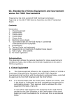
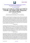
Using SensorLinkLitewires
with the Arbiter Systems
928A Power System Multimeter
R
Document No. PD0043800A
Arbiter Systems, Inc.
1324 Vendels Circle, Suite 121
Paso Robles, CA 93446
U.S.A.
(805) 237-3831, (800) 321-3831
http://www.arbiter.com
mailto: [email protected]
1
Introduction
Arbiter Systems manufactures the Model 928A Power System Multimeter. It has Floating-Point
DSP Digital Signal Analysis and is an AC Power measurement instrument, providing outstanding
performance and flexibility in a small, hand-held package. Not only does the Model 928A measure
basic data and power quantities, but it also measures power quality including harmonics, flicker,
sags, swells and interruptions. Incorporating a graphic LCD display, USB port, real time clock
and an unprecedented combination of features makes the Model 928A the ideal instrument for the
power professional.
While the Model 928A is designed for use on low voltages, it also can measure higher voltages by
R
using PTs and CTs. The SensorLink
Litewires provide a portable PT and CT that easily adapt
and have been evaluated in Arbiters Laboratories. Litewires are designed to measure primary
voltage and current, and as such are not to be left unattended. However, they are an excellent
way to capture primary waveforms.
The following information describes how to connect the Amp and Volt Litewire and configure the
928 for their use.
2
To connect a Volt Litewire to an Arbiter 928A:
2.1
•
•
•
•
2.2
Required Parts
R
20kV Volt Litewire SensorLink
Part# 8-012-60 Hz
R
Dual Banana Plug to BNC Connector SensorLink
Part# 7-011- CONN
Coax Cable with BNC Connectors on each end
Arbiter 928A Power System Multimeter
Connecting the Volt Litewire to the 928A
1. Connect the Dual Banana Plug to BNC Connector to Channel A of the Arbiter 928A (see
figure below). The Banana Plug has Red and Black plugs. Plug the Red lead into the Red
terminal and the Black into the Black terminal.
2. Connect the BNC Cable to the Analog output from the display of the Volt Litewire. And
the other end of the BNC Cable to the BNC end of the Banana Plug.
3
To connect an Amp Litewire to an Arbiter 928A:
3.1
•
•
•
•
Required Parts
R
Amp Litewire SensorLink
Part# 8-015-60Hz or 8-016 60Hz
Pomona Banana-to-BNC(m) adapter, Pomona Part# 1296
Arbiter Current Input to BNC Cable, Arbiter part# CA0027200
Arbiter 928A Power System Multimeter
2
3.2
Connecting the Amp Litewire to the 928A
1. Connect the Arbiter current cable (P/N CA0027200) into the Channel B current connector
on the Model 928A (see figure below). Current inputs are at the top of the 928A.
2. Connect the banana jacks at the other end of the Arbiter current cable to the
banana-to-BNC adapter. Plug the red banana plug of the current cable into the red jack of
the adapter, and black banana plug into the black banana jack of the adapter.
3. Connect the BNC connector of the adapter to the BNC connector of the analog output from
the display of the Amp Litewire.
4
Configure the Arbiter 928A to accept the Volt and Amp
Litewire Outputs
4.1
Select the Voltage and Current Channel
In this step, you will configure Channel A of the 928A to measure voltage and Channel B to
measure current. For reference, see pages 19-22 from the 928A User Manual.
1. On the 928A, press keys [2nd] then [AV] to set Channel A to voltage.
2. On the 928A, press keys [2nd] then [BI] to set Channel B to current.
4.2
Configure Voltage Ratio for Channel A on the 928A
In this step, you will configure Channel A of the 928A for the correct ratio to read the voltage
from the Volt Litewire. The correct value for the Volt Litewire is 10,000.
1. On the 928A, press keys [2nd] then [Menu] and use the arrow keys to highlight “Ch-A, V”
and press the [ENT] key.
2. In the “Ch A VOLTAGE CONFIG” screen the cursor should be resting on “INPUT
RATIO”. To adjust the voltage ratio, press the [ENT] key and the cursor should move to
the ratio value. Now, use the numeric keys to type in the value “10000” and press the
[ENT] key.
3. If you want to enter a phase offset, set the cursor to “PHASE OFFSET” and press the
[ENT] key. Use the numeric keys to enter any phase offset and press the [ENT] key.
4. To store these changes, highlight “<STOre And Exit>” and press the [ENT] key.
5. Press the [ESC] key to go back to the main screen.
3
4.3
Configure Current Ratio for Channel B on the 928A
In this step, you will configure Channel B of the 928A for the correct ratio to read the current
from the Amp Litewire. The correct value for the Amp Litewire is 1,000.
1. On the 928A, press keys [2nd] then [Menu] and use the arrow keys to highlight “Ch-B, I”
and press the [ENT] key.
2. In the “Ch B CURRENT CONFIG” screen the cursor should be resting on “CT SELECT”.
Press the [ENT] key and choose the selection, ‘USER” and press the [ENT] key.
3. In the “INPUT TYPE” selection, choose the value “Volt” and press the [ENT] key.
4. In the “INPUT RATIO” selection, choose the value 1000 and press the [ENT] key.
5. If you want to enter a phase offset, set the cursor to “PHASE OFFSET” and press the
[ENT] key. Use the numeric keys to enter any phase offset and press the [ENT] key.
6. In the “LOW RANGE MODE” selection, set the value to “OFF.”
7. To store these changes, highlight “<STOre And Exit>” and press the [ENT] key.
8. Press the [ESC] key to go back to the main screen.
5
Measuring Voltage and Current
The Model 928A should now be correctly configured and connected to measure primary voltage
R
and current using the SensorLink
Volt and Amp Litewires.
To read voltage and current, simply press the [VI] key. The Model 928A should be ready to
indicate voltage and current when the Litewires are positioned correctly on the lines.
4