1
3-Phase, 4-Wire Wye (3V, 3C) TR
Service Type File:
S000F09
Meter:
9S, 9A
Meter Type:
Transformer Rated
Voltage:
120/208 or 277/480
Current Transformers:
3
Voltage Transformers:
3 (if applicable)
Blondel’s Theorem Compliant:
Yes
MC Standard Drawings:
3416, 3417, 3418, 3419, 3455, 3456, 3457, 3458
PowerMaster Model(s):
5300, 7300
Firmware:
1.0.0.6
App Note Revision:
1.00
Introduction
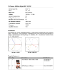
The simplest true 3-phase metering circuit is the 3-phase, 4-wire Y metered with a true 3 element
meter. In this service, there are 3 distinct voltage and current power pairs with each metered as if
it were a separate source returning through the neutral (ie, like 3 simultaneous 1-phase services
at 120° angle spacing).
No Lag (1.00 PF)
30˚ Lag (0.866 PF)
Required Equipment
Item
Qty.
Description
Part Number
1.
1
PowerMaster® Model 7300 or 5300
10-130-7300 or
10-130-5300
2.
1
3-Phase Test Switch Current Direct Probes
10-340-0027
3.
1
3-Phase Voltage Cable
10-340-0005
4.
1
3-Phase Probe Adapter Cable
10-340-0014
5.
1
36” Flexible Current Probe (600V, 1000A)
10-100-1036
6.
1
IR Pulse Detector
EP10-100-3327
Optional Equipment
The following equipment may be used as an alternate for the standard accessories:
Item Qty
Description
Part Number
Alternate For
7.
3
36” Flexible Current Probes
(600V, 1000A)
10-100-1036
Item #5
8.
1
Amp LiteWire
SLWIDE-02
Item #5
9.
3
MN353 Clamp-On Probes
10-100-3353
Item #2
10.
3
MN375 Clamp-On Probes
10-100-3375
Item #2
11.
1
Form 9 Meter Base Test Adapter 75-310-0013
N/A
12.
1
Isolated KYZ Contact Pickup
10-120-0005
Item #6
13.
1
Photo Disk Detector
EP10-100-3326
Item #6
Miscellaneous Equipment
Personal Protective Equipment (PPE)
Hot Stick (if using the Amp LiteWire)
Cloth or rag to prevent possible sunlight when using the IR Pulse Detector
Equipment Hookup
The labels correspond to the item numbers from the Required Equipment table above.
5
3
2
3
A = Red, B = Yellow, C = Blue, Neutral/Ground = Gray
Procedure
1. Power up the PowerMaster by pressing the ON key.
2. From the PowerMaster, connect the 3-Phase Test Switch Current Direct Probes to
CURRENT, and the 3-Phase Voltage Cable to VOLTAGE
3. Connect the 3-Phase Probe Adapter Cable to PROBE SET 1. Connect the 36” Flexible
Current Probe (600V, 1000A) to the adapter cable end for A phase (red).
4. Connect the 3-Phase Voltage Cable leads to the potentials of the test switch according to the
wiring diagram shown in “Equipment Hookup” (A=red, B=yellow, C=blue, Neutral=white,
Ground=green).
5. Connect the Auxiliary Power leads to a voltage source between 100-530VAC.
6. Insert the 3-Phase Test Switch Current Direct Probes into the current return of the test switch
according to the wiring diagram shown in “Equipment Hookup” (A=red, B=yellow, C=blue).
For polarity, the white side should face up. For safety, shunt the CT current before inserting
the probes. After insertion, re-engage the CT currents.
7. At the Main Menu, press 1 to “Select Site”
8. In the Site Editor, press F2 to create a new site. If the site is already present in the database,
skip to step 12.
9. In the Site Editor screen, enter the Site ID and select “3-Phase, 4 Wire Wye (3V, 3C) TR –
S000F09” for the service type.
10. Tab to “Test Setup,” and select the appropriate setup for this installation. To create or edit a
setup, press F4. For detailed information about the “Test Setup,” refer to Section 7.4.1.1 in
the User Manual.
OPTIONS
Goes to next page
Goes to Test Editor
11. Enter all other relevant fields in the Site Editor (required fields are in yellow). For detailed
information about the Site Editor, refer to Section 7 in the User Manual. Press F6 to continue.
OPTIONS
Goes to next page
Saves and continues
12. At the Site Editor, press F6 to select the site to be tested.
13. Enter the user’s name(s) and any comments regarding the installation. Press F6 to continue.
14. At the Main Menu, press 2 for “Integrated Site Test.”
15. In “Integrated Site Test,” review and confirm the test setup. Press F6 to continue.
16. The PowerMaster® will confirm if the probes and lead sets are connected properly for the
meter test. Install the IR Pulse Detector onto the meter and connect it to AUX DIGITAL on
the PowerMaster®. Press F6 to continue.
17. The PowerMaster® will now check for valid signals for the voltages and currents for the meter
test. Next, it will check for meter pulses. After meter pulses are detected, press F6 to
continue.
18. After the customer load meter test is complete, review the results. If within tolerance, press
F6 to continue.
OPTIONS
Go back to step 17
View trend plot
Continue
19. The PowerMaster® will confirm if the probes and lead sets are connected properly for the CT
test. Wrap the 36” Flexible Current Probe (600V, 1000A) around all of the primary conductors
for A phase CT. An arrow on the connector denotes polarity (arrow towards load). Press F6
to continue
20. Press F6 to test A phase CT.
21. View results for A phase CT. Wrap the 36” Flexible Current Probe (600V, 1000A) around all
of the primary conductors for B phase CT. Press F6 to continue.
OPTIONS
Retest A phase CT
Test B phase CT
22. View results for B phase CT. Wrap the 36” Flexible Current Probe (600V, 1000A) around all
of the primary conductors for C phase CT. Press F6 to continue.
OPTIONS
Retest B phase CT
Test C phase CT
23. View results for C phase CT. Press F6 to complete the test.
OPTIONS
Retest C phase CT
Go back to step 20
View graphical data
View numerical data
Complete testing
24. At the Main Menu, select and press Enter for “Recall Data.”
25. Select the site that was tested and review the data before leaving the site. Use up and down
arrows to select the site and F6 to expand and view the data. After review is complete, power
off the PowerMaster® by pressing the ON key.
OPTIONS
Select test
Open & view data
26. Carefully disconnect all lead sets and probes and properly store them in the accessory case.
Using Optional Equipment
Procedure Using Three 36” Flexible Current Probes (600V, 1000A)
1. Power up the PowerMaster by pressing the ON key.
2. From the PowerMaster, connect the 3-Phase Test Switch Current Direct Probes to
CURRENT, and the 3-Phase Voltage Cable to VOLTAGE.
3. Connect the 3-Phase Probe Adapter Cable to PROBE SET 1. Connect the 36” Flexible
Current Probes (600V, 1000A) to the adapter cable end for A phase (red), B phase (yellow),
and C Phase (blue).
4. Follow the procedure through steps 4-18 as normal.
5. Wrap the 36” Flexible Current Probes (600V, 1000A) around all of the primary conductors for
A, B, and C phase CT. An arrow on the connector denotes polarity (arrow towards load).
Press F6 to begin testing.
6. Follow the procedure through steps 23-26 as normal.
Procedure Using the Amp LiteWire
1. Power up the PowerMaster by pressing the ON key.
2. From the PowerMaster, connect the 3-Phase Test Switch Current Direct Probes to
CURRENT, and the 3-Phase Voltage Cable to VOLTAGE.
3. Connect the 3-Phase Probe Adapter Cable to PROBE SET 1. Connect the HV Signal Cable
to A phase (red) of the 3-Phase Probe Adapter Cable.
4. Connect the HV Signal Cable to the “Analog Output” (BNC) connector on the Amp LiteWire
receiver. Connect the male ends of the orange fiber optic cable to the female ends of the
transmitter and receiver (for detailed instructions, refer to the Amp LiteWire Operators
Manual). Carefully lay the Amp LiteWire aside.
5. Follow the procedure through steps 4-18 as normal
6. Use the Amp LiteWire’s chuck adapter to connect to a hot stick. Turn on the Amp LiteWire by
first turning on the receiver (press 2x) then the transmitter (press 2x). Once both modules are
powered on, the receiver will display 0.
7. Carefully lift the Amp LiteWire into the A phase CT conductors. For polarity, position the face
of the transmitter to the load side of the CT.
8. Press F6 to test A phase CT.
9. View results for A phase CT. Carefully lift the Amp LiteWire into the B phase CT conductors.
Press F6 to continue.
10. View results for B phase CT. Carefully lift the Amp LiteWire into the C phase CT conductors.
Press F6 to continue.
11. Follow the procedure through steps 23-26 as normal.
Procedure Using the MN353 or MN375 Clamp-On Probes
1. Power up the PowerMaster by pressing the ON key.
2. From the PowerMaster, connect the 3-Phase Probe Adapter Cable to PROBE SET 1, and the
3-Phase Voltage Cable to VOLTAGE.
3. Connect the MN353 or MN375 probes to the ends of the 3-Phase Probe Adapter Cable for
PROBE SET 1 (A = red, B = yellow, C = blue).
4. Connect the 3-Phase Voltage Cable leads to the potentials of the test switch according to the
wiring diagram shown in “Equipment Hookup” (A=red, B=yellow, C=blue, Neutral=white,
Ground=green).
5. Clamp the MN353 or MN375 probes around the secondary current path of the meter
installation according to the wiring diagram shown in “Equipment Hookup”. An arrow on the
probe denotes polarity (arrow towards load)
6. Connect the second 3-Phase Probe Adapter Cable to PROBE SET 2. Connect the 36”
Flexible Current Probe (600V, 1000A) to the adapter cable end for A phase (red).
7. Follow the procedure through steps 7-26 as normal.
Procedure using the Form 9 Meter Base Adapter
1. Follow the procedure through steps 1-3 as normal.
2. Remove the meter from the meter socket. Place the meter into the Form 9 Meter Base
Adapter. Firmly place the Form 9 Meter Base Adapter back into the meter base.
3. Connect the 3-Phase Voltage Cable leads to the potentials of the test switch according to the
wiring diagram shown in “Fig. 1” (VA=red, VB=yellow, VC=blue, VO=white, Ground=green)
4. Insert the 3-Phase Test Switch Current Direct Probes into the current return of the test switch
according to the wiring diagram shown in “Fig. 1” (COA=red, COB=yellow, COC=blue). For
safety, shunt the CT currents (CA, CB, CC) before inserting the probes. After insertion, reengage the CT currents.
5. Connect the Auxiliary Power leads to a voltage source between 100-530VAC.
6. Follow the procedure through steps 7-26 as normal.
Fig. 1
Procedure using the Isolated KYZ Contact Pickup
KYZ is a designation given to a relay used to create pulses for electrical metering applications. It
is commonly a Form C relay. The term KYZ refers to the contact designations: K for common, Y
for Normally Open, and Z for Normally Closed. When incorporated into an electrical meter, the
relay changes state with each rotation (or half rotation) of the meter disc. Each state change is
called a "pulse." When connected to the PowerMaster®, rate of use (kW) as well as total usage
(kWh) can be determined from the rate and quantity of pulses.
1. Follow the procedure through steps 1-15 as normal.
2. Connect the Isolated KYZ Contact Pickup to AUX DIGITAL on the PowerMaster®.
3. Connect the gray lead to K (common) and the orange lead to either Y (open) or Z (closed).
4. After pulses are detected, press F6 to continue.
5. Follow the procedure through steps 17-26 as normal.
Procedure using the Photo Disk Detector
1. Follow the procedure through steps 1-15 as normal.
2. Connect the Photo Disk Detector to AUX DIGITAL on the PowerMaster®.
3. Install the Photo Disk Detector on the mechanical meter. Line the red photoelectric light to
the rotating disk on the meter. Use the blue flathead screwdriver (supplied) to adjust the light
sensitivity for pulse detection.
4. After pulses are detected, press F6 to continue.
5. Follow the procedure through steps 17-26 as normal.
Optional Equipment Combinations
When combining optional equipment or using any other custom testing requirements, please
contact Powermetrix Technical Support for assistance.