1
m
TK-840
TK-940
TK-941
UHF FM TRANSCEIVER
800 MHz FM TRANSCEIVER
900 MHz FM TRANSCEIVER
INSTRUCTION MANUAL
EMETTEUR-RECEPTEURFM UHF
EMETTEUR-RECEPTEURFM 800 MHz
EMETTEUR-RECEPTEURFM 900 MHz
MODE D'EMPLOI
TRANSCEPTOR FM DE UHF
TRANSCEPTOR FM DE 800 MHz
TRANSCEPTOR FM DE 900 MHz
MANUAL DE INSTRUCCIONES
KENWOOD CORPORATION
@ 862-0459-10 (K)
12 11 10 09 08 07 06 05 04 03
ModelsCoveredByThis Manual:
TK-840:
UHF FM Transceiver (25 W)
TK-940:
800 MHz FM Transceiver (15 W)
TK-941:
900 MHz FM Transceiver (15 W)
This manual identifies and describes differences between the above versions.
NoticeToThe User:
IMPORTANT:
GOVERNMENT LA W PROHIBITS THE OPERA TION OF UNLICENSED
TRANSMITTERS WITHIN THE TERRITORIES UNDER GOVERNMENT
RADIO
CONTROL.
ILLEGAL OPERA TlON IS PUNISHABLE
OR BOTH.
REFER SERVICE
TO A QUALIFIED
BY FINE OR IMPRISONMENT
LICENSED OR CERTIFIED
TECHNICIAN
ONL Y.
One or more of the following statements may be applicable:
I
FCC WARNING
This equipment generates or uses radio frequency energy. Changes or modifications to this
equipment may cause harmful interference unless the modifications are expressly approved in
the instruction manual. The user could lose the authority to operate this equipment if an
unauthorized change or modification is made.
INFORMATION
TO THE DIGITAL DEVICE USER REQUIRED
BY THE FCC
This equipment has been tested and found to comply with the limits for a Class B digital
device, pursuant to Part 15 of the FCC Rules. These limits are designed to provide
reasonable protection against harmful interference in a residential installation.
This equipment generates, uses and can generate radio frequency energy and, if not installed
and used in accordance with the instructions, may cause harmful interference to radio
communications.
However, there is no guarantee that the interference will not occur in a
particular installation. If this equipment does cause harmful interference to radio or television
reception, which can be determined by turning the equipment off and on, the user is
encouraged to try to correct the interference by one or more of the following measures:
Reorient or relocate the receiving antenna.
Increase the separation between the equipment and receiver.
Connect the equipment to an outlet on a circuit different from that to which the receiver is
connected.
Consult the dealer for technical assistance.
---
li.if
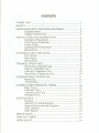
CONTENTS
THAN K YOU!
SAFETY
UNPACKING AND CHECKING EQUIPMENT
Supplied Items
Diagram References
...
INSTALLATION AND CONNECTION
Installation Equipment.
Planning the Installation.
Power Cable
Installing the Transceiver
Microphone
CONTROLS AND FUNCTIONS
Front Panel
Rear Panel...
Microphone
TRU NKED OPERATION
Receiving a Dispatch Call
Placing a Dispatch Call
Placing a Telephone Call
Receiving a Telephone Call
CONVENTIONAL OPERATION
Receiving
Transmitting
...
AUDIBLE USER FEEDBACK TONES
Busy Tone
Intercept Tone
Volume Level Tone
Proceed Tone
SYSTEM SCAN...
...
General
Scanning Trunked Systems
Scanning Conventional Systems
Scan Lockout
Scan Revert
GROUP SCAN
...
TIME-OUT TIMER
HORN ALERT
1
1
2
2
3
3
4
4
5
5
..5
6
6
8
8
9
9
9
10
10
11
11
11
12
12
12
12
12
13
13
13
13
13
13
14
14
14
THANKYOU!
We are grateful you chose KENWOOD for your land mobile applications. We
believe this easy-to-use transceiver will provide dependable communications
to keep personnel operating at peak efficiency.
KENWOOD transceivers incorporate the latest in advanced technology. As a
result, we feel strongly that you will be pleased with this product's quality and
features.
SAFETY
It is important that the operator is aware of and understands hazards
common to the operation of any transceiver.
WARNING!
.
EXPLOSIVE A TMOSPHERES (GASES, DUST, FUMES, etc.)
Turn off and do not operate your transceiver while taking on fuel, or while parked in
gasoline service stations. 00 not carry spare fuel containers in the trunk of your vehicle if
your transceiver is mounted in the trunk area.
.
INJURY FROM RADIO FREQUENCY
TRANSMISSIONS
00 not operate your transceiver when anyone is touching the antenna, or when anyone is
standing within two to three feet of your antenna, to avoid the possibility of radio frequency
burns or related physical injury.
.
DYNAMITE
BLASTING
CAPS
Dynamite blasting caps may explode by the operation of transceivers, if such operation
occurs within 500 feet of the blasting caps. Turn off and do not operate your transceiver
when in an area where blasting is in progress, or where "TURN OFF TWO-WA Y RADIO"
signs have been posted. If you are transporting blasting caps in your vehicle, make
certain they are carried in a closed metal box having a padded interior. 00 not transmit
during the time that caps are being placed into or removed from this container.
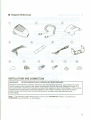
UNPACKING AND CHECKINGEQUIPMENT
Note: The following instructions are for use by your KENWOOD
KENWOOD service facility, or the factory.
dealer, an authorized
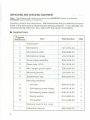
Carefully unpack the transceiver. We recommend that you identify the items
listed in the table before discarding the packing material. If any damage has
occurred during shipment, file a claim with the carrier immediately.
.
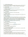
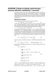
SuppliedItems
Diagram
Reference
Item
Part Number
Qty.
-
Transceiver
CD
Microphone
T91-0374-XX
1
@
Microphone cable
E30-2089-XX
1
G)
Microphone hanger
J19-1376-XX
1
@)
Power cable assembly
E30-2076-XX
1
@
Spare fuse (10 A)
F51-0016-XX
1
@
Mic. hanger ground cable
E30-2036-XX
1
(])
Mounting bracket
J29-0441-XX
1
@
Speaker-jack cap
B09-0235-XX
1
-
1
Mounting hardware
@
Hex bolt
N69-4010-XX
7
@
Self-tapping screw (large)
N46-5016-XX
4
@
Self-tapping screw (small)
N46-4016-XX
3
@
Spring washer
N16-0050-XX
4
@
Flat washer
N15-1050-XX
4
-
-
2
Warranty card (U.S.A. only)
Instruction manual
-
1
B62-0459-XX
1
~
.
Diagram
References
0
CD
@~
~
@
@)
0
@
~7)
':'is
@
b!J
@
~
6fY
@
@
~
~
~
@
@)
.
@
@
INSTAllATIONANDCONNECTION
WARNING!
INTERFERENCE
WITH VEHICULAR
ELECTRONICS
Electronic fuel injection systems, electronic anti-skid braking systems, and electronic cruise
control systems are typical of the types of electronic devices that may malfunction due to a
lack of protection from radio frequency energy that is present when transmitting. If the vehicle
contains such equipment, consult the dealer for the make of vehicle and enlist his aid in
determining if such electronic circuits will perform normally when the transceiver is
transmitting.
Note:
The following instructions are for use by your KENWOOD
KENWOOD service facility, or the factory.
dealer, an authorized
3
.
Installation
Equipment
CAUTION:
Take care when drilling mounting holes to avoid damaging vehicle wiring or
parts. Always check to see how far the mounting screws will extend below the mounting
surface before installing.
The following tools are required for installing this transceiver:
.
.
.
6 mm (1/4") or larger electric drill
Drills and circle cutters (sizes listed below)
04.2 mm (5/32")
05 x 16 self-tapping screws
03.2 mm (1/8")
04 x 16 self-tapping screws
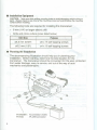
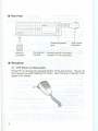
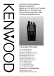
PlanningtheInstallation
The accompanying illustration should help you in planning your
installation. Before starting, determine the best location for the
transceiver. The transceiver should be convenient for the user, protected
from water damage, easy to service, and out of the way of auto
mechanics and passengers.
~/
TK-940/941: N connector (male)
TK-840:
PL-259 connector
4
.
PowerCable
The power cable consists of a fused red lead, a fused black lead, and a
2-pin power plug. To install the power cable, check for an existing hole
conveniently located in the firewall through which the cable can be
passed. If no hole exists, drill the firewall and install a rubber grommet.
Starting with the plug end of the cable at the transceiver, run the two
power leads into the engine compartment from the passenger
compartment. Connect the red lead to the positive (+) battery terminal or
switched power source, and the black lead to the negative (-) battery
terminal. Always locate the fuse as close to the battery as possible. Coil
up the surplus cable and secure it out of the way with the retaining strap
provided. Ensure enough slack is available in the cables so that the
transceiver can be removed for servicing with the power applied.
CAUTION:
The transceiver operates in 12 volt negative ground systems only! Always
check the battery polarity and voltage of the vehicle before installing the transceiver.
.
InstallingtheTransceiver
Mount the transceiver so that the controls are within easy reach of the
user. Use the mounting bracket as a template to locate the holes, then
drill the holes and mount the transceiver. Leave sufficient room at the rear
of the transceiver for cable connections. Before attaching the transceiver
to the bracket, connect the antenna connector and power plug to the
transceiver.
WARNING!
For passenger safety, mount the transceiver securely so that it will not break
loose in the event of a collision. This is especially important in station wagons, vans and
similar type installations where a loose transceiver could be extremely dangerous to the
vehicle occupants.
.
Microphone
Mount the microphone hanger so that the microphone is within easy reach
of the user. Neither the microphone nor microphone cable should
interfere with the safe operation of the vehicle. After mounting the
microphone hanger, connect the microphone plug to the microphone
connector on the front of the transceiver, then place the microphone on
the hanger.
5
~
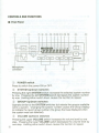
CONTROLS
ANDFUNCTIONS
.
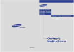
FrontPanel
CD@ @ @ @@ @ @ @
611 II~_~~:_-;~
@
CID
ijJ
4~IIBJBJllfl~NlJ~tJ
Microphone
connector
CD
.,
v~~
@
G)
~
@
POWERswitch
Press to switch the power ON or OFF.
@ SYSTEM Up/Down switches
Pressing the right SYSTEM switch increases the selected system number
by one. Pressing the left SYSTEM switch decreases the system number
by one. Holding either switch down causes the function to repeat.
GROUP Up/Down switches
Operate similar to the SYSTEM switches but selects the groups available
within a system. Changing the system number causes the Group Display
to indicate the revert group number (the group that was displayed when
the system was last selected).
CID
@ VOLUME Up/Down switches
Pressing the upper VOLUME switch increases the volume level by one
step. Pressing the lower VOLUME switch decreases the volume level by
one step. Holding either switch down causes the function to repeat.
6
@ AUX (Auxiliary) switch
Pressing this switch toggles the programmable auxiliary function such as
Horn Alert, Manual Relay, etc. Contact your dealer for further details.
@ SCAN switch
Pressing this switch toggles System Scan ON or OFF.
(J) Delete indicator
Appears when systems are locked out of the System Scan list. Blinks
while scanning if any systems are locked out.
@ TX indicator
Appears while the transceiver is in the transmit state.
@ BUSY indicator
Appears when attempting to access a trunked system that is busy with no
available repeaters.
@ CALL indicator
This indicator shows if a call was received while you were away from the
vehicle. It is programmed to appear when specific group IDs are received
(trunked systems) or when a call is received on a specific group that
opens the audio (conventional systems). The microphone hook-switch,
PTT, System, or Group keys will reset the CALL indicator. Call indicator
reset by other keys is decided by dealer programming.
@ Scan indicator
Appears while in the System Scan mode.
@ TA indicator
Appears when the Talk Around system/group is selected.
@ OPT indicator
Displays the status of Optional Signaling.
@ AUX (Auxiliary) indicator
Appears when the Manual Relay or Horn Alert function is activated (ON)
by pressing the AUX switch.
@ Handset indicator
Appears when a group is selected that is programmed with telephone IDs.
@ Alphanumeric display
After the dealer's qualified service technician programs the transceiver,
the Alphanumeric Display shows either system numbers and group
numbers for your specific network or the names of systems and/or groups.
7
.
RearPanel
i
Antenna
connector
External.speaker
jack
Input power
connector
(TK-940/941: Accepts male N connector.)
(TK-840:
Accepts PL-259 connector.)
. Microphone
QZ>
PTT(Push-To-Talk)switch
Press PIT to activate the transmit portion of the transceiver. Speak into
the microphone while holding PIT down. See "Placing a Dispatch Call"
{page 9} for details.
8
..
.
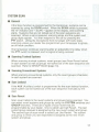
TRUNKED
OPERATION
Receiving
a Dispatch
Call
1 Switch ON the transceiver.
2 Press the VOLUME Up/Down switches to set the volume level. Use
the volume level tones as guides.
3 Select the system and group by using the SYSTEM switches and
GROUP switches. If the Scan function has been programmed, switch
this function ON or OFF as required.
4 When you hear the other party's voice, adjust the volume as
necessary.
. Placing
a Dispatch
Call
1 Select the system and group that you want to call by using the
SYSTEM switches and GROUP switches.
2 Press the PTT switch.
3 If the busy tone or intercept tone does not sound, communication is
possible; start speaking into the microphone. For best results, hold the
microphone 1 to 1.5 inches from your mouth. Release the PTT switch
when your message is complete and listen for a response. Press the
PTT switch to talk; release it to listen.
4 When your conversation is finished, return the microphone to its
hanger.
9
.
Placinga TelephoneCall
Note:
Telephone calls can be made only if that service is available and you have an
optional keypad-equipped
microphone. Consult your dealer for details.
1 Select the desired system and group that you want to call by using the
SYSTEM switches and GROUP switches.
2 Hold down the PTT switch for a moment (1 second) to ensure a
connection.
3 Release the PTT switch and confirm that you hear a dial tone from the
repeater.
4 Dial by using the microphone keypad. After dialing, wait for a response
from the other party.
5 When the other party responds, press the PTT switch and start
speaking. For best results, hold the microphone 1 to 1.5 inches from
your mouth. Release the PTT switch to listen to the other party. Only
one person can speak at a time.
6 To end the call, press the # key.
.
Receivinga TelephoneCall
1 Select the system and group by using the SYSTEM switches and
GROUP switches. If the Scan function has been programmed, switch
this function ON or OFF as required.
2 When you receive an incoming telephone call, you will hear a ringing
tone from the speaker.
3 Hold down the PTT switch to speak and release it to listen to the other
party.
4 To end the call, press the # key.
10
..:!.
.
CONVENTIONAL
OPERATION
Receiving
1 Switch ON the transceiver.
2 Press the VOLUME Up/Down switches to set the volume level. Use
the volume level tones as guides.
3 Select the system and group by using the SYSTEM switches and
GROUP switches. If the Scan function has been programmed, switch
this function ON or OFF as required.
4 When you hear the other party's voice, adjust the volume as
necessary.
.
Transmitting
Note:
Before transmitting, you must monitor the channel to make sure that it is not already
in use. If the selected group is not equipped with OT or DOT, monitoring is done by simply
listening for anyone talking before you begin transmitting. It is not necessary to take the
microphone off hook to monitor the channel. If the selected group is equipped with OT or
DOT (as advised by your dealer), take the microphone off hook to disable the OT or DOT.
Then if the channel is busy, you will hear the conversation.
1 Select the system and group that you want to call by using the
SYSTEM switches and GROUP switches.
2 Before starting to transmit, monitor the selected group to check if it is
free (see Note above). If the group is busy, wait until it is free.
3 Press the PTT switch and start speaking. For best results, hold the
microphone 1 to 1.5 inches from your mouth. Release the PTT switch
when your message is complete and listen for a response. Press the
PTT switch to talk; release it to listen.
4 When your conversation is finished, return the microphone to its
hanger.
11
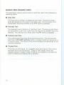
AUDIBLEUSERFEEDBACK
TONES
The transceiver outputs various tones to notify the user of the transceiver's
operating status.
.
BusyTone
The busy tone is similar to a telephone busy tone. The tone is output
when all repeaters in the system are being used. The tone stops when
transmission becomes possible or the PTT switch is released.
.
InterceptTone
The intercept tone is similar to a "high-low" siren. The tone sounds when
the transceiver is out of the system service area and a repeater cannot be
reached. The intercept tone stops when the PTT switch is released.
.
VolumeLevelTone
The volume level tone is the same as the busy tone. The tone sounds
each time a VOLUME Up/Down switch is pressed while the transceiver is
in receive mode. The volume of the tone increases and decreases as the
volume is adjusted.
.
ProceedTone
This tone is a short beep. It is available when the Clear-to-Talk function
has been set for the transceiver. "Clear-to-Talk" simply means the
repeater system is ready to begin handling your telephone call after you
have connected successfully with a repeater.
12
0:..,.
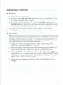
SYSTEMSCAN
.
General
If the Scan function is programmed for the transceiver, systems can be
scanned by using the SCAN switch. When the SCAN switch is pressed,
the "S" indicator and "- SCAN _"appear on the display, and scanning
starts. Systems that are not locked out of the scan sequence are
scanned. When a call is received, scanning stops and the system and
group digits appear. You then respond to the call by pressing the
PIT switch. Lifting the microphone from its hanger (off hook) stops
scanning unless your dealer has programmed your transceiver to ignore
an off hook condition.
The transceiver continues scanning after an adjustable time delay when
the PIT switch is released, and no signal is being received.
.
ScanningTrunkedSystems
When scanning trunked systems, revert groups (see Scan Revert below)
in each system as well as groups not locked out of the scan sequence are
scanned. Refer to GROUP SCAN {page 14}.
.
ScanningConventionalSystems
When scanning conventional systems, only the revert groups (channels)
in each system are scanned.
.
Scanlockout
If the AUX (Auxiliary) switch is programmed for the scan lockout function,
each system can be locked out of the scan sequence manually by the
user.
.
ScanRevert
Scan revert refers to the revert systems and groups being scanned. You
can select revert systems and groups by using the SYSTEM switches and
GROUP switches. There are 2 types of scan revert that are
programmable by your dealer. One is called Last Call Revert. The last
system/group received is assigned as the new revert system and group.
The second type of scan revert is called Last Use Revert. The system
and group to which you last responded is assigned as the new revert
system and group.
13
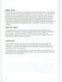
GROUP SCAN
The Group Scan function is available only for trunked systems. This function
is useful if more than one group is programmed in systems. The Group Scan
function is set by the dealer on request. It scans not only groups that are
allowed to be scanned but also the revert groups. When a call is received,
the group indicator shows the group number and that group becomes the
revert group. Simply press the PIT switch to respond to the call. As with
System Scan, lifting the microphone from its hanger (off hook) stops scanning
unless your dealer has programmed your transceiver to ignore an off hook
condition.
TIME-OUT
TIMER
The time-out timer stops continuous transmissions automatically after a
specified time elapses. The dealer sets the time in the range of 15 seconds
to 10 minutes. If you hold down the PIT switch for longer than the
programmed time, an alert tone sounds when the timer expires. The tone
stops after the PIT switch is released.
HORNALERT
If Horn Alert has been installed by your dealer, this function sounds the
vehicle horn or some other type of external alert when certain calls are
received. It is programmed like the CALL indicator to sound when specific
group IDs or calls are received.
If the AUX switch is programmed to control Horn Alert, then this function can
be activated or deactivated with this switch. The Auxiliary indicator appears
when Horn Alert is activated.
14
I~
,,'~
""
,,'~
,'~
,'~
",,.
,,'~
",,.
",,.
,'~
,'~
""
,'~
",
""
KENWOOD
WARRANTY ON LAND MOBILE
RADIOS AND ACCESSORIES
Kenwood
cessories,
Communications
as follows:
Corporation
("KENWOOD") warrants
its Land Mobile Radios and ac-
HOW LONG IS THE WARRANTY
This Warranty will remain in effect for two (2) years for radios, and one (1) year for accessories
(including rechargeable batteries). measured from the date of purchase by the first end user.
WHO IS PROTECTED
This Warranty is enforceable
only by the first end user.
WHAT IS COVERED
Except as specified below, this Warranty covers all defects in materials and workmanship
in
KENWOOD Land Mobile Radios and accessories. The following are not covered by the Warranty.
1. Damage, deterioration or failure resulting from:
A. Accident, misuse, abuse, neglect. product modification or failure to follow instructions contained in your Owner's Manual.
B. Repair or attempted repair by anyone not authorized by KENWOOD.
C. Installation of parts or accessories that do not conform to the quality or specifications of the
original parts or accessories.
D. Installation of the product in, or removal of the product from, the vehicle or other site of its
use.
2. Damage or loss occurring during shipment (claims must be presented to the carrier).
3. Any unit which is not new when sold to the first end user or upon which the serial number has
been defaced, modified or removed.
WHAT WE WILL PAY FOR AND WHAT YOU MUST PAY FOR
KENWOOD will pay all labor and material expenses for items covered by this Warranty. If it is
necessary to ship the product for Warranty service, you are responsible for the initial shipping
charges, but we will pay the return shipping charges if the product is repaired or replaced under
Warranty. You are responsible for any charges incurred in removing the product from the vehicle
or other site of use and for reinstallation of the repaired or replaced product.
HOW TO OBTAIN WARRANTY SERVICE
Your KENWOOD Land Mobile Radio or accessory
may be serviced
by any authorized
KENWOOD
Land Mobile dealer or service center. Whenever the product is presented for warranty service, you
must supply a sales receipt or other evidence
of the date of purchase.
EXCLUSION OF IMPLIED WARRANTIES AND DAMAGES
Unless considered unlawful or unenforceable
under applicable law:
A. ALL IMPLIED WARRANTIES WITH RESPECT TO KENWOOD LAND MOBILE RADIOS AND
ACCESSORIES, INCLUDING IMPLIED WARRANTIES OF MERCHANTABILITY AND FITNESS FOR
A PARTICULAR PURPOSE, HEREBYARE EXCLUDED.
B. KENWOOD'S LIABILITY UNDER THIS WARRANTY SHALL BE LIMITED TO THE REPAIR OR
REPLACEMENT, AT KENWOOD'S OPTION, OF ANY DEFECTIVE PRODUCT, AND SHALL NOT
INCLUDE DAMAGES OF ANY KIND, WHETHER INCIDENTAL, CONSEQUENTIAL OR OTHERWISE.
This Warranty
is enforceable
If a problem develops
only in the United States of America.
during or after the Limited Warranty
Period, or if you have any questions
regarding the operation of the product. you should contact your KENWOOD Authorized Dealer or
Authorized Service Center. If the problem or your question is not handled to your satisfaction,
please contact our Customer
For customers outside
outhorized dealer.
Relations Department
U.S.A. or Canada
KENWOOD
at the address
who purchase
listed below:
this product,
please contact
your local
SERVICE CORPORATION
P.O. Box 22745
2201 East Dominguez
Street
Long Beach CA 90801-5745 Phone: (310) 761-8275
;i"
.."
..,..
~"
~"
~"
~"
~"
~"
.."
~"
""--'-'r-.TT
.."
.."
.."
~"
,"
-'"