1
XServe Users Manual
Revision C, December 2006
PN: 7430-0111-01
© 2005-2006 Crossbow Technology, Inc. All rights reserved.
Information in this document is subject to change without notice.
Crossbow, MoteWorks, MICA, TrueMesh and XMesh are registered trademarks of Crossbow
Technology, Inc. Other product and trade names are trademarks or registered trademarks of their
respective holders.
XServe User’s Manual
Table of Contents
1
Introduction........................................................................................................................... 1
1.1
1.2
1.3
2
Installation and Getting Started .......................................................................................... 4
2.1
2.2
2.3
2.4
2.5
3
Supported Platforms and Operating Systems.......................................................................... 4
Mote Tier Requirements ......................................................................................................... 4
PC Installation Steps ............................................................................................................... 4
MoteWorks Sensor and Data Acquisition Applications .......................................................... 4
Starting XServe with MoteWorks applications [Quick Start] ................................................. 6
Using XServe ......................................................................................................................... 8
3.1
3.2
4
Wireless Mesh Networking Overview .................................................................................... 1
XServe Overview .................................................................................................................... 2
XServe Services Overview...................................................................................................... 2
XServe Overview..................................................................................................................... 8
XServe Command Line Parameters......................................................................................... 9
Using XCommand ............................................................................................................... 18
4.1
4.2
4.3
4.4
4.5
XCommand Overview ........................................................................................................... 18
Using XServeTerm................................................................................................................ 18
Using XML RPC................................................................................................................... 23
XML RPC Document Structure ............................................................................................ 24
XCommand XML RPC Document Structure........................................................................ 25
5
Using XServe Web Interface .............................................................................................. 34
6
Using Xserve Modbus Interface ......................................................................................... 38
6.1
6.2
6.3
7
Advanced Xserve Functionality ......................................................................................... 41
7.1
7.2
7.3
7.4
8
XServe Architecture.............................................................................................................. 41
Parsers ................................................................................................................................... 43
Data Sinks ............................................................................................................................. 52
Properties Files...................................................................................................................... 59
Appendix A: Mote Packet Reference ................................................................................ 60
8.1
8.2
8.3
8.4
9
Modbus Overview ................................................................................................................. 38
Modbus Message Structure ................................................................................................... 38
Using XServe Modbus Interface............................................................................................ 39
TinyOS Header...................................................................................................................... 60
XMesh Header ...................................................................................................................... 60
XSensor Header .................................................................................................................... 61
CRC....................................................................................................................................... 62
Appendix B: Sensor Packet Reference.............................................................................. 63
9.1
9.2
9.3
9.4
9.5
9.6
MTS101................................................................................................................................. 63
MTS300................................................................................................................................. 67
MTS310................................................................................................................................. 68
MTS400................................................................................................................................. 71
MTS420................................................................................................................................. 72
MDA300 ............................................................................................................................... 79
Doc.# 7430-0111-01 Rev. C
Page i
XServe User’s Manual
9.7
9.8
9.9
9.10
9.11
9.12
9.13
9.14
10
MTS510................................................................................................................................. 83
MDA500 ............................................................................................................................... 87
MEP510................................................................................................................................. 91
MEP410................................................................................................................................. 95
MDA320 ............................................................................................................................... 99
MSP410............................................................................................................................... 104
MDA100 ............................................................................................................................. 108
MTS410............................................................................................................................... 112
Appendix C: Sensor Data Conversions....................................................................... 120
10.1
10.2
10.3
10.4
10.5
10.6
10.7
10.8
10.9
10.10
10.11
10.12
10.13
11
Converting Battery Reading for MICA2............................................................................. 120
Converting Battery Reading for MICA2DOT..................................................................... 120
Converting Thermistor Reading.......................................................................................... 121
Converting Thermistor Reading in Celsius ......................................................................... 122
Converting Voltage of an ADC Channel ............................................................................ 123
Converting Voltage of an ADC Channel using Reference.................................................. 123
Converting Moisture Reading ............................................................................................. 124
Converting ADC Count of Accelerometer.......................................................................... 125
Converting ADC Count of Thermistor................................................................................ 125
Converting ADC Count of Humidity.............................................................................. 126
Converting ADC Count of Barometric Pressure/Temperature ....................................... 126
Intersema Temperature Conversion................................................................................ 128
Davis Soil Temperature Conversion............................................................................... 128
Appendix D: Health Packet Reference ....................................................................... 130
11.1
Health Messages.................................................................................................................. 130
Appendix D: Heartbeat Packet Reference.............................................................................. 133
11.2
12
Heartbeat Messages............................................................................................................. 133
Appendix E: XCommand Packet Reference .............................................................. 134
12.1
12.2
12.3
12.4
13
XCommand Messages ......................................................................................................... 134
XCommand Query ............................................................................................................... 135
XCommand Response.......................................................................................................... 135
XCommand XML RPC Reference ...................................................................................... 136
Appendix F: Connection Protocols.............................................................................. 182
13.1
13.2
14
Serial Framer Protocol ........................................................................................................ 182
Serial Forwarder Protocol ................................................................................................... 183
Appendix G: Database Administration ...................................................................... 185
14.1
14.2
14.3
15
PostgreSQL ......................................................................................................................... 185
SQL ..................................................................................................................................... 185
Database Tools .................................................................................................................... 186
Appendix H: XServe Simulator................................................................................... 188
15.1
16
Data Simulation................................................................................................................... 188
Appendix I: Upgrading XServe Handlers to XServe Datasinks ................................ 191
16.1
Page ii
Differences between previous versions of XServe and current XServe.............................. 191
Doc.# 7430-0111-01 Rev. C
XServe User’s Manual
16.2
Upgrading XServe Handlers to XServe Datasinks............................................................... 191
Doc.# 7430-0111-01 Rev. C
Page iii
XServe User’s Manual
About This Document
The following annotations have been used to provide additional information.
; NOTE
Note provides additional information about the topic.
; EXAMPLE
Examples are given throughout the manual to help the reader understand the terminology.
3 IMPORTANT
This symbol defines items that have significant meaning to the user
WARNING
The user should pay particular attention to this symbol. It means there is a chance that physical
harm could happen to either the person or the equipment.
The following paragraph heading formatting is used in this manual:
1 Heading 1
1.1 Heading 2
1.1.1 Heading 3
This document also uses different body text fonts (listed in Table 0-1) to help you distinguish
between names of files, commands to be typed, and output coming from the computer.
Table 0-1. Font types used in this document.
Font Type
Usage
Courier New Normal
Sample code and screen output
Courier New Bold
Commands to be typed by the user
Times New Roman Italic TinyOS files names, directory names
Franklin Medium Condensed
Page iv
Text labels in GUIs
Doc.# 7430-0111-01 Rev. C
XServe User’s Manual
1 Introduction
1.1
Wireless Mesh Networking Overview
Wireless sensor networks have attracted a wide interest from industry due to their diversity of
applications. Sensor networks are pervasive by nature; the number of nodes in a network is
nearly boundless. Therefore, a key to realizing this potential is multi-hop mesh networking,
which enables scalability and reliability.
A mesh network is really a generic name for a class of networked embedded systems that share
several characteristics including:
y
Multi-Hop—the capability of sending messages peer-to-peer to a base station, thereby
enabling scalable range extension;
y
Self-Configuring—capable of network formation without human intervention;
y
Self-Healing—capable of adding and removing network nodes automatically without having
to reset the network; and
y
Dynamic Routing—capable of adaptively determining the route based on dynamic network
conditions (e.g., link quality, hop-count, gradient, or other metric).
When combined with battery power management, these characteristics allow sensor networks to
be long-lived, easily deployed, and resilient to the unpredictable wireless channel. With mesh
networking, the vision of pervasive and fine-grained sensing becomes reality.
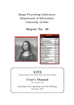
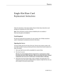
A wireless network deployment is composed of the three distinct software tiers:
y
The Client Tier provides the user visualization software and graphical interface for
managing the network. Crossbow provides free client software called MoteView that bundles
software from all three tiers to provide an end-to-end solutions.
y
The Server Tier is an always-on facility that handles translation and buffering of data
coming from the wireless network and provides the bridge between the wireless motes and
the internet clients. XServe and XOtap are server tier applications that can run on a PC or
Stargate.
y
The Mote Tier, where XMesh resides, is the software the runs on the cloud of sensor nodes
forming a mesh network. The XMesh software provides the networking algorithms required
to form a reliable communication backbone that connects all the nodes within the mesh cloud
to the server.
Doc.# 7430-0111-01 Rev. C
Page 1
XServe User’s Manual
Figure 1-1. Software Framework for a Wireless Sensor Network
1.2
XServe Overview
XServe serves as the primary gateway between wireless mesh networks and enterprise
applications interacting with the mesh. At its core, XServe provides services to route data to and
from the mesh network with higher level services to parse, transform and process data as it flows
between the mesh and the outside applications. Higher level services are customizable using
XML based configuration files and loadable plugin modules.
XServe offers multiple communication inputs for applications wishing to interact with XServe or
the mesh network. Users can interact with XServe through a terminal interface where as
applications can access the network directly or through a powerful XML RPC command
interface.
1.3
XServe Services Overview
XServe provides different levels of service depending on how it is configured and installed.
y
Serial Forwarder: At its core XServe provides basic routing services to the Mote network.
As a serial forwarder XServe allows applications to communicate directly with the
application. Applications send and receive raw data directly to the mote network with no
high level parsing, converting or processing. In serial forwarding mode, XServe applications
installed on multiple machines can form a chain of routing modules forwarding data from the
Mote tier through an enterprise network.
y
Application Server: XServe can act as an application server providing higher level services
such as parsing, transforming and processing data at run time. Users can parse Mote tier data
Page 2
Doc.# 7430-0111-01 Rev. C
XServe User’s Manual
from the compact raw data format used by motes into a set of named data values. While
parsing, data can be converted, merged or separated at bit level granularity based on the
semantic meaning of the data. Parsed data can be sent for extra processing by user defined
business logic. XServe provides pre-configured post processing modules for printing data to
the terminal screen, writing data to file, storing data in a database, and publishing data as an
XML stream.
Doc.# 7430-0111-01 Rev. C
Page 3
XServe User’s Manual
2 Installation and Getting Started
2.1
Supported Platforms and Operating Systems
XServe is supported on the following platforms:
Operating System
Platform
Windows/Cygwin
X86
Linux
X86
ARM
2.2
Mote Tier Requirements
XServe directly connects to a mesh network through a base station mote. Base station motes can
be connected to the XServe machine using the following hardware:
y
MIB510 serial gateway using an RS-232 serial port or a USB port and a USB-to-serial
converter that is compatible with the PC and its operating system.
y
MIB520 serial gateway using a USB port.
y
MIB600 Ethernet gateway using a wired Ethernet or 802.11 wireless card only if the
MIB600 is on a LAN with wireless access.
y
Direct Serial Connection using the 51 pin connector on the Stargate platform.
2.3
PC Installation Steps
1. Shut down all running programs on your computer.
2. Insert the MoteWorks CD into the computer’s CD-ROM drive.
3. Follow the steps provided in MoteWorks Getting Started Guide.
2.4
MoteWorks Sensor and Data Acquisition Applications
XServe supports all Crossbow sensor and data acquisition applications. MoteWorks provides two
variants of each application:
1. XMesh enabled applications: XMesh is Crossbow’s multihop mesh networking protocol that
has various options including low-power listening, time synchronization, sleep modes, anyto-base and base-to-any routing. All of our sensor and data acquisition boards are supported
with XMesh enabled applications. XServe is connected to these applications thorugh a base
station running the XMeshBase application. The Table 2-1 provides a summary of the XMesh
applications the corresponding sensor boards.
Page 4
Doc.# 7430-0111-01 Rev. C
XServe User’s Manual
Table 2-1. Sensor and data acquisition boards and the corresponding XMesh application
Sensor and Data
Acquisition Boards
2.
Application Name
Location of Driver Folder
MDA100CA
XMDA100
MoteWorks/apps/XMesh/XMDA100
MDA100CB
XMDA100CB
MoteWorks/apps/XMesh/XMDA100CB
MDA300
XMDA300
MoteWorks/apps/XMesh/XMDA300
MDA320
XMDA320
MoteWorks/apps/XMesh/XMDA320
MDA325
XMDA325
MoteWorks/apps/XMesh/XMDA325
MDA500
XMDA500
MoteWorks/apps/XMesh/XMDA500
MEP410
XMEP410
MoteWorks/apps/XMesh/XMEP410
MEP510
XMEP510
MoteWorks/apps/XMesh/XMEP510
MSP410
XMSP410
MoteWorks/apps/XMesh/XMSP410
MTS101
XMTS101
MoteWorks/apps/XMesh/XMTS101
MTS300CA/310CA
XMTS310
MoteWorks/apps/XMesh/XMTS310
MTS300CB/310CB
XMTS310CB
MoteWorks/apps/XMesh/XMTS310CB
MTS410
XMTS410
MoteWorks/apps/XMesh/XMTS410
MTS400/420
XMTS420
MoteWorks/apps/XMesh/XMTS420
MTS450
XMTS450
MoteWorks/apps/XMesh/XMTS450
MTS510
XMTS510
MoteWorks/apps/XMesh/XMTS510
XSensor applications: XSensor applications are test applications for Crossbow’s sensor and
data acquisition boards. They allow the user to quickly and easily test sensor and data
acquisition boards when attached to Mote. These applications send the output over the
Mote’s UART thereby allowing the user to test these boards without using an RF link.
Testing by RF link can also be done by programming a base station with TOSBase and
connecting it to XServe. XSensor application send data one hop so all test Motes must be
within RF range of the base station. The Table 2-2 provides a summary of the XSensor
applications the corresponding sensor boards.
Table 2-2. Sensor and data acquisition boards and the corresponding XSensor application
Sensor and Data
Acquisition Boards
Application Name
Location of Driver Folder
MDA100
XSensorMDA100
MoteWorks/apps/XSensor/ XSensorMDA100
MDA300
XSensorMDA300
MoteWorks/apps/XSensor/XSensorMDA300
MDA320
XSensorMDA320
MoteWorks/apps/XSensor/XSensorMDA320
MDA325
XSensorMDA325
MoteWorks/apps/XSensor/XSensorMDA325
MDA500
XSensorMDA500
MoteWorks/apps/XSensor/XSensorMDA500
MEP410
XSensorMEP410
MoteWorks/apps/XSensor/XMEP410
MEP510
XSensorMEP510
MoteWorks/apps/XSensor/XSensorMEP510
MTS101
XSensorMTS101
MoteWorks/apps/XSensor/XSensorMTS101
MTS300/310
XSensorMTS300
MoteWorks/apps/XSensor/XSensorMTS300
MTS400/420
XSensorMTS400
MoteWorks/apps/XSensor/XSensorMTS400
MTS410
XSensorMTS410
MoteWorks/apps/XSensor/XSensorMTS410
MTS450
XSensorMTS450
MoteWorks/apps/XSensor/XSensorMTS450
MTS510
XSensorMTS510
MoteWorks/apps/XSensor/XSensorMTS510
Doc.# 7430-0111-01 Rev. C
Page 5
XServe User’s Manual
; NOTE: Instructions on how to compile and install these applications are in MoteWorks Getting
Started Guide.
2.5
Starting XServe with MoteWorks applications [Quick Start]
XServe is pre-configured to work with all MoteWorks sensor applications. Before starting
XServe, refer to MoteWorks Getting Started Guide to learn how to compile, install, and deploy a
MoteWorks sensor network. Once a network has been deployed, run XServe on the PC
connected to the Mote Tier base station.
To quickly begin viewing sensor data connect XServe to the COM device connected to your
sensor network base station using the following command:
xserve.exe –device=com<#>
The <#> is to be replaced by the COM port number to which the MIB510 or MIB520 (the higher
of the two virtual COM ports assigned by your PC) is attached. Starting XServe in this manner
automatically displays each sensor network packet directly to the terminal screen in 3 different
formats: a) raw, b) parsed, and c) converted.
y
Raw Format: Raw format displays the data in it pure binary form displaying each byte of
the data as a pair of base16 hexidecimal numbers. Raw format is useful for debugging sensor
data since data is displayed unaltered, in the same format sent by the motes over the network.
y
Parsed Format: Parsed format displays the data as a set of name-values pairs. XServe
parses the raw format and extracts individual fields of data associating them with the field
name. Parsed format displays the field name of the data with original base16 hexidecimal
number associated with it.
y
Converted Format: Converted format also displays the data as name-values pairs, but each
value has been converted from its raw value into the appropriate unit of measure for the field.
Below is an example out from an XMTS101 application data packet. The packet is displayed in
raw, parsed and converted formats.
$ xserve -device=com4
XServe Ver 2: $Id: xserve.c,v 1.24 2005/12/14 10:05:13 pipeng Exp $
Using params: [raw] [parsed] [converted] [server port=9001]
Opening serial device: \\.\COM4 @ 57600
[2005/12/20 14:57:56]
Serial Source Msg: sync
[2005/12/20 14:57:56] 7E 00 00 91 14 82 01 01 00 7E 01 04 01 F1 00 2C 01 F3 00 F
2 00 F5 00 FE 00
[25]
[2005/12/20 14:57:56] MTS101 [sensor data converted to engineering units]:
health:
node id=0x01
tempurature: =0x104 degC
battery:
= 0x17e mv
light: = 0xf1 mv
adc0 = 0x12c mv adc1 = 0xf3 mv adc2 = 0xf2 mv
adc3 = 0xf5 mv adc4 = 0xfe mv
[2005/12/20 14:57:56] MTS101 [sensor data converted to engineering units]:
Page 6
Doc.# 7430-0111-01 Rev. C
XServe User’s Manual
health:
node id=1
battery:
tempurature: =3.581866 degC
= 3278 mv
light: = 772 mv
adc0 = 300 mv adc1 = 243 mv adc2 = 242 mv
adc3 = 245 mv adc4 = 254 mv
Doc.# 7430-0111-01 Rev. C
Page 7
XServe User’s Manual
3 Using XServe
3.1 XServe Overview
XServe is a versatile application which can be configured to format and present data in multiple
manners. It can connect to the Mote Tier directly or through other forwarding applications
including other XServes. XServe also provides built in monitoring and conversion tools for
greater reliability and versatility.
At its core XServe provides basic routing services to the Mote network. As a serial forwarder
XServe allows enterprise applications to communicate directly with the sensor network.
Applications send and receive raw data directly to the mote network with no high level parsing,
converting or processing. In serial forwarding mode, XServe applications installed on multiple
machines can form a chain of routing modules forwarding data from the mote tier through an
enterprise network. For more information on the Serial Forwarding protocol (See Section 7.1.3).
XServe also provides higher level services for enterprise applications by abstracting the sensor
network so enterprise applications can focus on business logic. XServe can be configured to
parsing sensor packets into a series of name values pairs giving richer meaning to the sensor
data. While parsing, XServe can transform the data from its raw format to the appropriate unit of
measure for the sensor reading. Once parsed, sensor data can be presented in multiple formats
based on an individual applications needs.
3.1.1
XServe Data Formats
XServe manages data in three different formats: a) raw, b) parsed, and c) converted.
y
Raw Format: Raw format displays the data in it pure binary form displaying each byte of
the data as a pair of base16 hexidecimal numbers. Raw format is useful for debugging sensor
data since data is displayed unaltered, in the same format sent by the motes over the network.
y
Parsed Format: Parsed format displays the data as a set of name-values pairs. XServe
parses the raw format and extracts individual fields of data associating them with the field
name. Parsed format displays the field name of the data with original base16 hexidecimal
number associated with it.
y
Converted Format: Converted format also displays the data as name-values pairs, but each
value has been converted from its raw value into the appropriate unit of measure for the field.
3.1.2
XServe Presentation Formats
XServe is pre-configured to present data in four ways: a) print, b) export file, c) database
logging, and d) XML (extenstible markup lanuage) data stream.
y
Print: Print displays all data directly to the terminal screen. By default xserve displays all
data to screen for users to view.
y
Export File: Export file exports each data packet to its own data specific file. Each packet
is entered as a single row in the file and each field is delimited using a user specified
delimiter. The filename and delimiter for MoteWorks application are specified in the
applications XML Configuration file (See Section 7.2.1). If the no configuration file is
Page 8
Doc.# 7430-0111-01 Rev. C
XServe User’s Manual
available for the data packet then the data is displayed on to the display terminal in a comma
delimited format.
y
Database Logging: Database logging stores each data packet in its own data specific
database table. Each packet represents a single row in the table. The packet can either be
inserted as a new row or can be used to update an existing row. The configuration for each
MoteWorks application data packet is specified in the applications Configuration XML file
(See Section 7.2.1).
y
XML Stream: XML Stream presents each data packet as an XML document. The XML
document is published to listening applications thorugh an XML socket connection. If no
applications are listening the XML Document is displayed to the terminal screen.
3.2
XServe Command Line Parameters
Usage: xserve <-?|r|a|p|c|xr|xp|xc|dbxmlr|xmlp|xmlc|v|alert|m>
<-l=tablename>
<-dbserver=servername> <-dbport=portnum>
<-dbname=database name> <-dbuser=username>
<-dbpasswd=password>
<-h=path,hostname,portnum,config_file>
<-m=com,baud,protocol,slaveaddress,defaultregistervaluesas>
<-xmlfile=filename> <-xmlport=portnum>
[<-sf=hostname:port> | <-fsf=hostname:port> | <-device=dev>]
<-port=num> <-baud=num> <-platform=plt>
<-debug=level>
<-configfiles=filename:filename:>
<-loadparsers=filename:filename:...>
<-loaddatasinks=filename:filename:...>
<-heartbeat=<num missed>
-?
= display help [help]
-r
= raw display of tos packets [raw]
-a
= ascii display of tos packets [ascii]
-p
= parsed display of tos packets [parsed]
-c
= converted display of tos packets [conveted]
-xr
= raw tos packets xported to file [export raw]
-xp
= parsed tos packets exported to file [export parsed]
-xc
= converted tos packets exported to file [export converted]
-db
= parsed tos packets exported to db [database parsed]
-dbserver
= database server name (default=localhost)
-dbport
= database server port number (default=5432)
-dbname
= database name (default=MoteView db)
Doc.# 7430-0111-01 Rev. C
Page 9
XServe User’s Manual
-dbuser
= database user (default=MoteView user)
-dbpasswd
= database user password (default=MoteView user password)
-l
= parsed tos packets exported to db
(deprecated) [database parsed]
-xmlr
= raw tos packets exported to xml [xml raw]
-xmlp
= parsed tos packets exported to xml [xml parsed]
-xmlc
= converted tos packets exported to xml [xml converted]
-xmlfile
= file name to store exported xml (default=screen)
-xmlport
= port number to start the xml server
-v
= show version of all modules
-h
= display data through web server
-m
= export data using modbus
-port
= set server port <default = 9001>
-sf
= connect to unframed serial forwarder
-fsf
= connect to framed serial forwarder
-device
= connect to serial device <default = /dev/ttyS0>
-baud
= set serial baud rate <default = 57600>
-platform
= set platform. <default = mica2>
values=mica2dot|mica2|mica|telos|micaz
-debug
= set debug level. <default = DBG_WARNING>
-alert
= alert when data values are above/below specified ranges
-daemon
= run in daemon mode
-nomonitor = run without a system monitor
-configfiles = load xml configuration files.
-loadparsers = load only the listed parsers files.
(default=all files are loaded)
-loaddatasinks = load only the listed datasinks files.
(default=all files are loaded)
-heartbeat = turn on the heartbeat monitor and reset after <num missed>
-convZto2
= convert incoming network packets from micaZ headers to
mica2 headers and vice versa
-conv2toZ
= convert incoming network packets from mica2 headers to
micaZ headers and vice versa
3.2.1
System Parameters
-v
Displays version numbers for each XServe loaded component.
-daemon
Page 10
Doc.# 7430-0111-01 Rev. C
XServe User’s Manual
By default XServe starts as a forground process. The –daemon flag starts XServe as a
background process.
-nomonitor
XServe is run as group of processes all monitored by a parent process. The –nomonitor
flags runs XServe as a single process.
3.2.2
Serial Forwarding Parameters
-port=<portnum>
Sets the Serial Forwarder server port number for applications wishing to connect to
XServe through Serial Forwarder. The default is 9001.
3.2.3
Mote Tier Connection Parameters
-sf=<hostname:port>
Connects to Mote Tier through an application running an unframed Serial Forwarding
protocol (See Section 7.1.3).
-fsf=<hostname:port>
Connects to the Mote Tier through an application running a framed Serial Forwarding
protocol (See Section 7.1.3).
-device=<COM#>
Connects to Mote Tier through a direct COM port. The default connection is to COM1.
-baud=<baudrate>
Sets the baud rate for the COM device. The default value is 56700.
3.2.4
Print Parameters
-r
Displays packets to terminal screen in base16 hexidecimal format
$ xserve -r
XServe Ver 2: $Id: xserve.c,v 1.24 2005/12/14 10:05:13 pipeng Exp $
Using params: [raw] [server port=9001]
Opening serial forwarder: localhost : 9001
[2005/12/19 09:29:36] 7E 00 33 7D 1B 00 00 00 00 00 00 00 01 81 7E 00 C0 00 D9 0
1 56 01 DA 00 B2 00 AE 00 BC 00 A4 00
[32]
-a
Displays packet to terminal screen in ASCII character format
-p
Displays packet to terminal screen in parsed format.
$ xserve -p
XServe Ver 2: $Id: xserve.c,v 1.24 2005/12/14 10:05:13 pipeng Exp $
Doc.# 7430-0111-01 Rev. C
Page 11
XServe User’s Manual
Using params: [parsed] [server port=9001]
Opening serial forwarder: localhost : 9001
[2005/12/19 09:29:36] MDA500 [sensor data converted to engineering units]:
health:
node id=0x00
battery:
volts=0xc0 mv
thermistor: resistance=0x1d9 ohms, tempurature=0x1d9 C
adc chan 2: voltage=0x156 mv
adc chan 3: voltage=0xda mv
adc chan 4: voltage=0xb2 mv
adc chan 5: voltage=0xae mv
adc chan 6: voltage=0xbc mv
adc chan 7: voltage=0xa4 mv
-c
Displays packet to terminal screen in converted format.
$ xserve -c
XServe Ver 2: $Id: xserve.c,v 1.24 2005/12/14 10:05:13 pipeng Exp $
Using params: [converted] [server port=9001]
Opening serial forwarder: localhost : 9001
[2005/12/19 09:29:36] MDA500 [sensor data converted to engineering units]:
health:
node id=0
battery:
volts=3200 mv
thermistor: resistance=8600 ohms, tempurature=28.201022 C
adc chan 2: voltage=1069 mv
adc chan 3: voltage=681 mv
adc chan 4: voltage=556 mv
adc chan 5: voltage=544 mv
3.2.5
Export File Parameters
-xr
Exports packet to file in raw format.
$ xserve -device=com4 -xr
XServe Ver 2: $Id: xserve.c,v 1.24 2005/12/14 10:05:13 pipeng Exp $
Using params: [export raw] [server port=9001]
Opening serial device: \\.\COM4 @ 57600
0x7E00009114820101007E01FF00EB005701EF00ED00F500FC00
-xp
Exports packet to file in parsed format.
Page 12
Doc.# 7430-0111-01 Rev. C
XServe User’s Manual
$ xserve -device=com4 -xp
XServe Ver 2: $Id: xserve.c,v 1.24 2005/12/14 10:05:13 pipeng Exp $
Using params: [export parsed] [server port=9001]
Opening serial device: \\.\COM4 @ 57600
0x0,0x01,0x91,0x82,0x1,0x17e,0xff,0xeb,0x157,0xef,0xed,0xf5,0xfc
-xc
Exports packet to file in converted format.
$ xserve -device=com4 -xc
XServe Ver 2: $Id: xserve.c,v 1.24 2005/12/14 10:05:13 pipeng Exp $
Using params: [export converted] [server port=9001]
Opening serial device: \\.\COM4 @ 57600
0,1,145,130,1,3278,3.097866,753,343,239,237,245,252
3.2.6
Database Logging Parameters
-db
Logs packet to database in parsed format.
$ ./xserve -device=com4 -db
XServe Ver 2: $Id: xserve.c,v 1.24 2005/12/14 10:05:13 pipeng Exp $
Using params: [db parsed] [server port=9001]
Opening serial device: \\.\COM4 @ 57600
[2005/12/20 16:18:53]
Serial Source Msg: sync
INSERT into mts101_results (result_time,nodeid,voltage,temp,light,adc0,adc1,adc2
,adc3,adc4) values (now(),1,382,260,240,311,247,240,244,254)
-dbserver=<servername>
Sets the PostgreSQL database server name. The default value is “localhost”.
-dbport=<portnum>
Sets the PostgreSQL database server port. The default value is 5432.
-dbname=<database name>
Sets the PostgreSQL database name. The default value is the MoteView database.
-dbuser=<username>
Sets the PostgreSQL database user name. The default is the MoteView database user
name.
-dbpasswd=<password>
Sets the PostgreSQL database user password. The default is the MoteView database user
password.
Doc.# 7430-0111-01 Rev. C
Page 13
XServe User’s Manual
3.2.7
XML Stream Parameters
-xmlr
Exports the packet to a XML stream in raw format.
$ xserve -device=com4 -xmlr
XServe Ver 2: $Id: xserve.c,v 1.24 2005/12/14 10:05:13 pipeng Exp $
Using params: [xml raw] [server port=9001]
Opening serial device: \\.\COM4 @ 57600
<?xml version="1.0" ?>
<MotePacket>
<RawPacket>0x7E00009114820101007E01FF00EA004101EE00EB00F100F700</RawPacket>
</MotePacket>
-xmlp
Exports the packet to a XML stream in parsed format.
$ xserve -device=com4 -xmlp
XServe Ver 2: $Id: xserve.c,v 1.24 2005/12/14 10:05:13 pipeng Exp $
Using params: [xml parsed] [server port=9001]
Opening serial device: \\.\COM4 @ 57600
<?xml version="1.0" ?>
<MotePacket>
<ParsedDataElement><Name>amtype</Name><RawValue>0x0</RawValue></ParsedDataElement>
<ParsedDataElement><Name>nodeid</Name><RawValue>0x01</RawValue></ParsedDataElement>
<ParsedDataElement><Name>group</Name><RawValue>0x91</RawValue></ParsedDataElement>
<ParsedDataElement><Name>board_id</Name><RawValue>0x82</RawValue></ParsedDataElement>
<ParsedDataElement><Name>packet_id</Name><RawValue>0x1</RawValue></ParsedDataElement>
<ParsedDataElement><Name>voltage</Name><RawValue>0x17e</RawValue></ParsedDataElement>
<ParsedDataElement><Name>temp</Name><RawValue>0xff</RawValue> </ParsedDataElement>
<ParsedDataElement><Name>light</Name><RawValue>0xea</RawValue></ParsedDataElement>
<ParsedDataElement><Name>adc0</Name><RawValue>0x141</RawValue></ParsedDataElement>
<ParsedDataElement><Name>adc1</Name><RawValue>0xee</RawValue></ParsedDataElement>
<ParsedDataElement><Name>adc2</Name><RawValue>0xeb</RawValue></ParsedDataElement>
<ParsedDataElement><Name>adc3</Name><RawValue>0xf1</RawValue></ParsedDataElement>
<ParsedDataElement><Name>adc4</Name><RawValue>0xf7</RawValue></ParsedDataElement>
</MotePacket>
-xmlc
Exports the packet to a XML stream in converted format.
Page 14
Doc.# 7430-0111-01 Rev. C
XServe User’s Manual
$ xserve -device=com4 -xmlr -xmlp -xmlc
XServe Ver 2: $Id: xserve.c,v 1.24 2005/12/14 10:05:13 pipeng Exp $
Using params: [xml raw] [xml parsed] [xml converted] [server port=9001]
Opening serial device: \\.\COM4 @ 57600
<?xml version="1.0" ?>
<MotePacket>
<ParsedDataElement><Name>amtype</Name><ConvertedValue>0</ConvertedValue></ParsedDataE
lement>
<ParsedDataElement><Name>nodeid</Name><ConvertedValue>1</ConvertedValue></ParsedDataE
lement>
<ParsedDataElement><Name>group</Name><ConvertedValue>145</ConvertedValue></ParsedData
Element>
<ParsedDataElement><Name>board_id</Name><ConvertedValue>130</ConvertedValue></ParsedD
ataElement>
<ParsedDataElement><Name>packet_id</Name><ConvertedValue>1</ConvertedValue></ParsedDa
taElement>
<ParsedDataElement><Name>voltage</Name><ConvertedValue>3278</ConvertedValue></ParsedD
ataElement>
<ParsedDataElement><Name>temp</Name><ConvertedValue>3.097866</ConvertedValue></Parsed
DataElement>
<ParsedDataElement><Name>light</Name><ConvertedValue>749</ConvertedValue></ParsedData
Element>
<ParsedDataElement><Name>adc0</Name><ConvertedValue>321</ConvertedValue></ParsedDataE
lement>
<ParsedDataElement><Name>adc1</Name><ConvertedValue>238</ConvertedValue></ParsedDataE
lement>
<ParsedDataElement><Name>adc2</Name><ConvertedValue>235</ConvertedValue></ParsedDataE
lement>
<ParsedDataElement><Name>adc3</Name><ConvertedValue>241</ConvertedValue></ParsedDataE
lement>
<ParsedDataElement><Name>adc4</Name><ConvertedValue>247</ConvertedValue></ParsedDataE
lement>
</MotePacket>
-xmlfile=<filename>
Specifies location to store XML stream if no subscribers connected to receive the XML
document. The default location is to the terminal screen.
-xmlport=<portnum>
The port number XML stream subscribers must connect to to receive XML docments.
The default is 9002.
3.2.8
Web Access Parameters
-h=<path,hostname,portnum,configfile>
Doc.# 7430-0111-01 Rev. C
Page 15
XServe User’s Manual
XServe provides a built in Web Server to access XServe’s web interface. The –h flag
starts the web server. The path is the location of the web directory, the hostname is name
of the web server machine, the portnum is the port to access the web server and the
config file is the path to a configuration file to configure the web server. By default the
values are <../web, localhost, 8080, NULL>. See Section 5.
3.2.9
Modbus Parameters
-m=<COM#,baudrate,protocol, slave address,default reg values>
Exports data via Modbus interface. The default value on windows platform is
“/dev/ttyS2,9600,RTU,32,0”.
3.2.10 Configuration Parameters
-configfiles=<filename1:filename2:…>
Loads only the specified XML configuration files. The default value is to load all XML
configuration files.
-loadparsers=<filename1:filename2:…>
Loads only the specified parser libraries. The default value is to load all available parser
libraries.
-loaddatasinks=<filename1:filename2:…>
Loads only the specified datasink libraries. The default value is to load all available
datasink libraries.
3.2.11 System Monitoring Parameters
-alert
XServe can monitor individual fields in packets to alert users if the value has over/under
specified values. The –alert flags turns on this monitoring feature (See Section 7.3.1.4).
-heartbeat=<num missed>
XServe can monitor the link to the base station to verify that it is running. In the case of
the MIB5x0 series of Sensor Programming Boards, the heartbeat monitor can also restart
the base station if a failure has been detected (See Section 7.3.1.6).
3.2.12 System Tools Parameters
-convZto2
XServe provides system tools to convert MICAz platform TinyOS packets to MICA2
TinyOS packets. When the –convZto2 flags is provided all packets from the Mote Tier
will be converted from MICAz to MICA2 packets, and all packets to the Mote Tier will
be converted from MICA2 packets to MICAz packets.
-conv2toZ
XServe provides system tools to convert MICA2 platform TOS packets to MICAz TOS
packets. When the –conv2toZ flag is provided all packets from the Mote Tier will be
Page 16
Doc.# 7430-0111-01 Rev. C
XServe User’s Manual
converted from MICA2 to MICAz packets, and all packets to the Mote Tier will be
converted from MICAz packets to MICA2 packets.
3.2.13 Debug Parameters
-debug=<debuglevel>
XServe provides various levels of debugging output. The available debug levels are:
XDBG_1 (most detail)
XDBG_2
XDBG_3
XDBG_4
XDBG_5 (least detail)
XDBG_INFO
XDBG_WARNING (default value)
XDBG_ERROR
Doc.# 7430-0111-01 Rev. C
Page 17
XServe User’s Manual
4 Using XCommand
4.1
XCommand Overview
MoteWorks sensor applications allow users to query state variables and actuate devices on the
Mote such as LEDS, sounder, or relays. This feature is called XCommand. XServe provides two
interfaces for enterprise applications to send commands to the MoteTier using XCommand.
Users can send and receive XCommands using XServeTerm, a terminal command application.
Applications can send and receive XCommands using an XML RPC interface.
The XCommand allow you to get, set, or reset parameters for the sensor boards. The Table 4-1
shows the command categories and commands.
Table 4-1 XCommand Categories and Description
Command
Category
Command
Power
Management
RESET
SLEEP
WAKEUP
Basic Update
Rate
SET_RATE
Mote
Configuration
Parameter
Settings
•
•
•
•
•
Actuation
ACTUATE
•
SET_LED
0=OFF, 1=ON, 2=TOGGLE
•
SET_SOUND
0=OFF, 1=ON
•
SET_RELAY
0=OFF, 1=ON
Arguments
Description
To reset the sleep and wakeup
time.
To get or set the update rate. The
set_rate command changes the
data acquisition duty cycle of the
mote. The first argument is the
new timer interval in milliseconds.
This set of commands allows you
to get and set radio frequency and
power, including channel.
GET_CONFIG
SET_NODEID
SET_GROUP
SET_RF_POWER
SET_RF_CHANNEL
This set of commands actuates
each individual LED with the
option to operate on all three
LEDs.
This command turns the sounder
off or on.
This command turns the relays on
or off.
Each command responds back with an acknowledgement to confirm that it has received the
command. The only exceptions are actuation commands. They do not send an
acknowledgement response.
4.2
Using XServeTerm
The XServeTerm application provides a terminal interface to XCommand. To start XServeTerm
use the following command:
Page 18
Doc.# 7430-0111-01 Rev. C
XServe User’s Manual
xserveterm –server=<host:port>
Starting XServeTerm in this manner will connect the application to the XServe running at host
and listening on port.
4.2.1
XServeTerm Parameters
XServeTerm has many modes of operation. The list of these command line options is provided
below.
Usage: xcommand <-?> <-server=host:port> <-network=xmesh|xsensor>
-?
= display help [help]
-server
= xserve command port [host:port]
-network
= network type (default = xmesh) [xmesh|xsensor]
-seq
= starting sequence number (default=100)
-group
= network group id (default=145)
-server
XServeTerm uses XServe to communicate with the Mote Tier. The –server flag gives
the host and port number of the XServe application connected to the sensor network. By
default the host is localhost and the port is 9003.
-network=<xmesh|xsensor>
MoteWorks provides two types of sensor applications: XSensor applications and XMesh
applications. The –network flag indicates which type of sensor application XServeTerm
is sending commands to. The default value is XMesh.
-seq=<number>
When communicating with XSensor applications XCommand requires a unique sequence
number for each command. The –seq flag sets the starting sequence number XServeTerm
will use when communicating with the network. The sequence number is incremented
internally after each executed command. The default value is 100.
-group=<groupid>
The –group flag sets the network group id for the network you are connecting too. The
default value is 145.
4.2.2
XCommand Parameters
Once you have started XServeTerm, the user will be given a command prompt from which to
issue commands. To obtain a list of commands type the following:
XCmdTerm> help
The help command will list all available commands and arguments. The list of these command
line options is provided below.
Available Commands:
set_timeout <timeout ms>
set_starting_sequence <sequence number>
set_default_group <group id>
Doc.# 7430-0111-01 Rev. C
Page 19
XServe User’s Manual
get_config
<destination address>
set_rate <destination address> <new rate>
set_nodeid <destination address> <new node id>
set_groupid <destination address>
<new group id>
set_rfchannel <destination address>
set_rfpower <destination address>
<new rf channel>
<new rfpower>
sleep <destination address>
wake <destination address>
reset <destination address>
xserve.shutdown
actuate <destination address> <device> <state>
device ids
states
----------
------
green led
0
off
0
yellow led
1
on
1
red led
2
toggle
2
all leds
3
sounder
4
relay1
5
relay2
6
relay3
7
set_timeout <timeout ms>
Each command (except Actuation commands) returns a response. The set_timeout flag
tells XServeTerm the amount of time the application should wait for a response. The
default value is 5000 ms.
set_starting_sequence <sequence number>
The sequence number is used by XSensor applications as a unique identifies for each
command. The starting value can be set at startup as an XServeTerm aruguement or at
run time using the set_starting_sequence command.
set_default_group <group id>
This sets the default group id for each command. It can be set at startup as an
XServeTerm argument or at run time using the set_default_group command.
get_config <destination address>
The get_config command requests configuration information from <destination
address>.
XCmdTerm:> get_config 5
SUCCESS: Command executed successfully. (SUCCESS:Success)
NODE ID: 5
UID: 01301FED0A00007D
Page 20
Doc.# 7430-0111-01 Rev. C
XServe User’s Manual
GROUP ID: 125
RADIO CHANNEL: 24
RADIO POWER: 15
set_rate <destination address> <new rate>
The set_rate command sets the sampling rate of the application at <destination
address> to new sample rate <new rate>.
XCmdTerm:> set_rate 5 100
SUCCESS: Command executed successfully. (SUCCESS:Success)
NODE ID: 5
SAMPLE RATE: 100
set_nodeid <destination address> <new node id>
The set_nodeid command sets the node id of the mote at <destination address> to
node id <new node id>.
XCmdTerm:> set_nodeid 5 10
SUCCESS: Command executed successfully. (SUCCESS:Success)
NODE ID: 10
set_groupid <destination address> <new group id>
The set_groupid command sets the group id of the mote at <destination address>
to group id <new group id>
XCmdTerm:> set_groupid 10 145
SUCCESS: Command executed successfully. (SUCCESS:Success)
NODE ID: 10
GROUP ID: 145
set_rfchannel <destination address> <new rf channel>
The set_rfchannel command sets the radio channel of the mote at <destination
address> to channel <new rf channel>
XCmdTerm:> set_rfchannel 10 23
SUCCESS: Command executed successfully. (SUCCESS:Success)
NODE ID: 10
RADIO CHANNEL: 23
set_rfpower <destination address> <new rfpower>
The set_rfpower command sets the radio power of the mote at <destination
address> to setting <new rf power>
XCmdTerm:> set_rfpower 10 15
SUCCESS: Command executed successfully. (SUCCESS:Success)
NODE ID: 10
RADIO POWER: 15
Doc.# 7430-0111-01 Rev. C
Page 21
XServe User’s Manual
sleep <destination address>
The sleep command directs the application to stop sampling data. This does not sleep
the radio, only the applications sampling.
XCmdTerm:> sleep 10
SUCCESS: Command executed successfully. (SUCCESS:Success)
NODE ID: 10
wake <destination address>
The wake command directs the application to resume sampling data.
XCmdTerm:> wake 10
SUCCESS: Command executed successfully. (SUCCESS:Success)
NODE ID: 10
reset <destination address>
The reset command directs the mote to do a hardware reset.
XCmdTerm:> reset 10
SUCCESS: Command executed successfully. (SUCCESS:Success)
NODE ID: 10
xserve.shutdown
The xserve.shutdown command shutsdown the xserve application it is connected to,
disconnecting all external connections and cleaning up all processes. The
xserve.shutdown command does not have a response.
actuate <destination address> <device> <state>
The actuate command allows users to actuate various devices on each of the Motes by
setting the state of the device. Table 4-2 provides a list of devices and their
corresponding states.
Table 4-2 Available Device State Options for Actuate Command
Device
Device ID
Device States
GREEN LED
0
OFF=0, ON=1, TOGGLE=2
YELLOW LED
1
OFF=0, ON=1, TOGGLE=2
RED LED
2
OFF=0, ON=1, TOGGLE=2
ALL LED
3
OFF=0, ON=1, TOGGLE=2
SOUNDER
4
OFF=0, ON=1, TOGGLE=2
RELAY 1
5
OFF=0, ON=1, TOGGLE=2
RELAY 2
6
OFF=0, ON=1, TOGGLE=2
RELAY 3
7
OFF=0, ON=1, TOGGLE=2
XCmdTerm:> actuate 10 2 0
SUCCESS: Command executed successfully. (SUCCESS:Success)
NODE ID: 10
Page 22
Doc.# 7430-0111-01 Rev. C
XServe User’s Manual
4.3
Using XML RPC
The XCommand API in XServe is presented as a set of XML RPC (remote procedure calls)
functions. XML RPC is simple framework that allows computers to execute remote procedures
using XML. In a typical exchange a computer sends an XML document to a specifed XServe
command port (9003) and XServe executes the command. After execution the result is wrapped
in an XML document and sent over the connection back to the requesting computer.
XServe implements a simple communication protocol over TCP/IP to send XML documents back
and forth. The first 4 bytes over the socket indicate the length of the payload. The bytes are in
network byte order. XServe expects all applications to send and to receive requests using this
protocol. Below is an example XCommand XML RPC document:
<?xml version="1.0" encoding="UTF-8"?>
<methodCall>
<methodName>xsensor.sleep</methodName>
<params>
<param>
<value>
<struct>
<member>
<name>seqNumber</name>
<value>
<int>108</int>
</value>
</member>
<member>
<name>destAddress</name>
<value>
<int>0</int>
</value>
</member>
<member>
<name>groupId</name>
<value>
<int>145</int>
</value>
</member>
</struct>
</value>
</param>
</params>
</methodCall>
Doc.# 7430-0111-01 Rev. C
Page 23
XServe User’s Manual
4.4
XML RPC Document Structure
4.4.1
MethodCall Tag
The root document of an XML RPC method call is the <methodCall> tag. Each XML RPC call
must contain one and only one <methodCall> tag.
<methodCall>
…
</methodCall>
4.4.2
MethodName Tag
The actual name of the remote procedure to be executed is wrapped in the <methodName> tag.
There is only one instance of <methodName> inside the <methodCall> tag.
<methodName>
METHODNAME
</methodName>
4.4.3
Parameters Tag
Method arguments are passed as a set of parameters. XCommand methods accept a single
parameter. The argument is an array of of name-value pairs. Each name-value pair represents
one of the arguments for the method. The ordering of the name-value pairs in the array does not
matter.
<params>
<param>
<value>
<struct>
<member>
<name>PARAMETER NAME</name>
<value>
<int>PARAMETER VALUE</int>
</value>
</member>
…
</struct>
</value>
</param>
</params>
</methodCall>
The value parameter is wrapped in a type which indicates the type of value being sent. Available
values are <int>, <boolean>, <string>, <double>, <dateTime.iso8601>, and <base64>.
Examples of each type are provided in Table 4-3 below.
Page 24
Doc.# 7430-0111-01 Rev. C
XServe User’s Manual
Table 4-3 Example Parameter Tags
Type
Definition
Example Value
<int>
4 byte signed integer
-12
<Boolean>
Binary true or false values
0 (false) or 1 (true)
<string>
String value
Hello world
<double>
Double precision floating
point number
12.215
<dateTime.iso8601>
Date/Time
11980717T14:08:55
<base64>
Base64 encoded binary
W91IGNhbid0IHJlYWQgdGhpcyE=
The complete XML RPC specifications can be found at http://www.xmlrpc.com.
4.5
4.5.1
XCommand XML RPC Document Structure
XMesh XML RPC Commands
MethodName:
xmesh.get_config: Requests configuration information from a Mote.
Arguments:
Name
Description
Value Type
destAddress
The node id from which configuration
information is requested.
<int>
groupId
The group id of the XMesh network
<int>
Name
Description
Value Type
codeNumber
The response code
<int>
codeName
The name of the response
<string>
codeDescription
A text description of the response code
<string>
nodeId
The node id of the responding Mote.
<int>
groupId
The group id of the responding Mote.
<int>
rfPower
The radio power of the responding Mote.
<int>
rfChannel
The radio channel of the responding Mote.
<int>
uidString
The 64 bit unique identifies for the mote as a
hexadecimal string
<string>
Response:
MethodName:
xmesh.set_rate: Sets the sampling rate of destination address’ application.
Arguments:
Name
Description
Value Type
destAddress
The node id to which the command is sent
<int>
Doc.# 7430-0111-01 Rev. C
Page 25
XServe User’s Manual
groupId
The group id of the XMesh network
<int>
newRate
The new sampling rate for the node
<int>
Name
Description
Value Type
codeNumber
The response code
<int>
codeName
The name of the response
<string>
codeDescription
A text description of the response code
<string>
nodeId
The node id of the responding Mote.
<int>
rate
The sampling rate the node is set after the
command
<int>
Response:
MethodName:
xmesh.set_nodeid: Sets the node id of the destination address.
Arguments:
Name
Description
Value Type
destAddress
The node id to which the command is sent
<int>
groupId
The group id of the XMesh network
<int>
newNodeId
The new node id for this node
<int>
Name
Description
Value Type
codeNumber
The response code
<int>
codeName
The name of the response
<string>
codeDescription
A text description of the response code
<string>
nodeId
The node id of the Mote after execution of
the command
<int>
Response:
MethodName:
xmesh.set_groupid: Sets the group id of destination address.
Arguments:
Name
Description
Value Type
destAddress
The node id to which the command is sent
<int>
groupId
The group id of the XMesh network
<int>
newGroupId
The new group id for this node
<int>
Response:
Page 26
Name
Description
Value Type
codeNumber
The response code
<int>
codeName
The name of the response
<string>
codeDescription
A text description of the response code
<string>
Doc.# 7430-0111-01 Rev. C
XServe User’s Manual
nodeId
The node id of the responding Mote.
<int>
groupId
The group id of the Mote after executing the
command
<int>
MethodName:
xmesh.set_rfchannel: Sets the radio channel of destination address.
Arguments:
Name
Description
Value Type
destAddress
The node id to which the command is sent
<int>
groupId
The group id of the XMesh network
<int>
newRfChannel
The new radio channel for this node
<int>
Response:
Name
Description
Value Type
codeNumber
The response code
<int>
codeName
The name of the response
<string>
codeDescription
A text description of the response code
<string>
nodeId
The node id of the responding Mote.
<int>
rfChannel
The radio channel after executing the
command
<int>
MethodName:
xmesh.set_rfpower: Sets the radio power of destination address.
Arguments:
Name
Description
Value Type
destAddress
The node id to which the command is sent
<int>
groupId
The group id of the XMesh network
<int>
newRfPower
The new radio power for this node
<int>
Name
Description
Value Type
codeNumber
The response code
<int>
codeName
The name of the response
<string>
codeDescription
A text description of the response code
<string>
nodeId
The node id of the responding Mote.
<int>
rfPower
The radio power after executing the
command
<int>
Response:
MethodName:
xmesh.reset: Resets the destination address.
Doc.# 7430-0111-01 Rev. C
Page 27
XServe User’s Manual
Arguments:
Name
Description
Value Type
destAddress
The node id to which the command is sent
<int>
groupId
The group id of the XMesh network
<int>
Name
Description
Value Type
codeNumber
The response code
<int>
codeName
The name of the response
<string>
codeDescription
A text description of the response code
<string>
Response:
MethodName:
xmesh.wake: Directs the application to resume sampling data
Arguments:
Name
Description
Value Type
destAddress
The node id to which the command is sent
<int>
groupId
The group id of the XMesh network
<int>
Name
Description
Value Type
codeNumber
The response code
<int>
codeName
The name of the response
<string>
codeDescription
A text description of the response code
<string>
Response:
MethodName:
xmesh.sleep: Directs the application to stop sampling data
Arguments:
Name
Description
Value Type
destAddress
The node id to which the command is sent
<int>
groupId
The group id of the XMesh network
<int>
Response:
Name
Description
Value Type
codeNumber
The response code
<int>
codeName
The name of the response
<string>
codeDescription
A text description of the response code
<string>
MethodName:
Page 28
Doc.# 7430-0111-01 Rev. C
XServe User’s Manual
xmesh.actuate: Actuates a device on the Mote
Arguments:
Name
Description
Value Type
destAddress
The node id to which the command is sent
<int>
groupId
The group id of the XMesh network
<int>
actDevice
The id of the device to actuate
<int>
actState
The state to set the specified device
<int>
Name
Description
Value Type
codeNumber
The response code
<int>
codeName
The name of the response
<string>
codeDescription
A text description of the response code
<string>
Response:
4.5.2
XSensor XML RPC Commands
MethodName:
xsensor.get_config: Requests configuration information from a Mote.
Arguments:
Name
Description
Value Type
seqNumber
The unique sequence number for the
command
<int>
destAddress
The node id to which the command is sent
<int>
groupId
The group id of the XMesh network
<int>
Name
Description
Value Type
codeNumber
The response code
<int>
codeName
The name of the response
<string>
codeDescription
A text description of the response code
<string>
nodeId
The node id of the responding Mote.
<int>
groupId
The group id of the XMesh network
<int>
rfPower
The radio power of the responding Mote.
<int>
rfChannel
The radio channel of the responding Mote.
<int>
uidString
The 64 bit unique identifier for the Mote
<int>
Response:
MethodName:
xsensor.set_rate: Sets the sampling rate of destination address’ application.
Arguments:
Name
Doc.# 7430-0111-01 Rev. C
Description
Value Type
Page 29
XServe User’s Manual
seqNumber
The unique sequence number for the
command
<int>
destAddress
The node id to which the command is sent
<int>
groupId
The group id of the XMesh network
<int>
newRate
The new sampling rate for the node
<int>
Name
Description
Value Type
codeNumber
The response code
<int>
codeName
The name of the response
<string>
codeDescription
A text description of the response code
<string>
nodeId
The node id of the responding Mote.
<int>
rate
The sampling rate the node is set after the
command
<int>
Response:
MethodName:
xsensor.set_nodeid: Sets the node id of the destination address.
Arguments:
Name
Description
Value Type
seqNumber
The unique sequence number for the
command
<int>
destAddress
The node id to which the command is sent
<int>
groupId
The group id of the XMesh network
<int>
newNodeId
The new node id for this node
<int>
Response:
Name
Description
Value Type
codeNumber
The response code
<int>
codeName
The name of the response
<string>
codeDescription
A text description of the response code
<string>
nodeId
The node id of the Mote after execution of
the command
<int>
MethodName:
xsensor.set_groupid: Sets the group id of destination address.
Arguments:
Page 30
Name
Description
Value Type
seqNumber
The unique sequence number for the
command
<int>
destAddress
The node id to which the command is sent
<int>
groupId
The group id of the XMesh network
<int>
Doc.# 7430-0111-01 Rev. C
XServe User’s Manual
newGroupId
The new group id for this node
<int>
Name
Description
Value Type
codeNumber
The response code
<int>
codeName
The name of the response
<string>
codeDescription
A text description of the response code
<string>
nodeId
The node id of the Mote after execution of
the command
<int>
groupId
The group id of the Mote after executing the
command
<int>
Response:
MethodName:
xsensor.set_rfchannel: Sets the radio channel of destination address.
Arguments:
Name
Description
Value Type
seqNumber
The unique sequence number for the
command
<int>
destAddress
The node id to which the command is sent
<int>
groupId
The group id of the XMesh network
<int>
newRfChannel
The new radio channel for this node
<int>
Name
Description
Value Type
codeNumber
The response code
<int>
codeName
The name of the response
<string>
codeDescription
A text description of the response code
<string>
nodeId
The node id of the Mote after execution of
the command
<int>
rfChannel
The radio channel after executing the
command
<int>
Response:
MethodName:
xsensor.set_rfpower: Sets the radio power of destination address.
Arguments:
Name
Description
Value Type
seqNumber
The unique sequence number for the
command
<int>
destAddress
The node id to which the command is sent
<int>
groupId
The group id of the XMesh network
<int>
newRfPower
The new radio power for this node
<int>
Doc.# 7430-0111-01 Rev. C
Page 31
XServe User’s Manual
Response:
Name
Description
Value Type
codeNumber
The response code
<int>
codeName
The name of the response
<string>
codeDescription
A text description of the response code
<string>
nodeId
The node id of the Mote after execution of
the command
<int>
rfPower
The radio power after executing the
command
<int>
MethodName:
xsensor.reset: Resets the destination address.
Arguments:
Name
Description
Value Type
seqNumber
The unique sequence number for the
command
<int>
destAddress
The node id to which the command is sent
<int>
groupId
The group id of the XMesh network
<int>
Name
Description
Value Type
codeNumber
The response code
<int>
codeName
The name of the response
<string>
codeDescription
A text description of the response code
<string>
Response:
MethodName:
xsensor.wake: Directs the application to resume sampling data
Arguments:
Name
Description
Value Type
seqNumber
The unique sequence number for the
command
<int>
destAddress
The node id to which the command is sent
<int>
groupId
The group id of the XMesh network
<int>
Name
Description
Value Type
codeNumber
The response code
<int>
codeName
The name of the response
<string>
codeDescription
A text description of the response code
<string>
Response:
MethodName:
Page 32
Doc.# 7430-0111-01 Rev. C
XServe User’s Manual
xsensor.sleep: Directs the application to stop sampling data.
Arguments:
Name
Description
Value Type
seqNumber
The unique sequence number for the
command
<int>
destAddress
The node id to which the command is sent
<int>
groupId
The group id of the XMesh network
<int>
Name
Description
Value Type
codeNumber
The response code
<int>
codename
The name of the response
<string>
codeDescription
A text description of the response code
<string>
Response:
MethodName:
xsensor.actuate: Actuates a device on the mote
Arguments:
Name
Description
Value Type
seqNumber
The unique sequence number for the
command
<int>
destAddress
The node id to which the command is sent
<int>
groupId
The group id of the XMesh network
<int>
actDevice
The id of the device to actuate
<int>
actState
The state to set the specified device
<int>
Response:
4.5.3
Name
Description
Value Type
codeNumber
The response code
<int>
codeName
The name of the response
<string>
codeDescription
A text description of the response code
<string>
XServe XML RPC Commands
MethodName:
xserve.shutdown: Shuts down the XServe server it is connected to.
Arguments:
No arguements
Response:
No response
Doc.# 7430-0111-01 Rev. C
Page 33
XServe User’s Manual
5 Using XServe Web Interface
User can access XServe and perform most of the functions via web interface. It is convenient for
user who is far away from the server. There are four main functions in web interface that are
listed below:
•
Health report
•
Real time data parsing
•
Command
•
XOTAP.
To run web interface in XServe, use
-h
or –h with options (items contained within the less than/greater than brackets <>)
-h=<MainPage,HostName,Port,ConfigFile>
The -h will use default setting for the web interface, which is “../web,localhost,8080”.
; NOTE: Run XServe from /opt/MoteWorks/tools/xserve/bin/bin in order for the web interface to work.
After XServe starts with the -h option, the user can access XServe via web interface. Open a web
browser, and go to http://localhost:8080 or http://hostname:8080 . The web page shown in Figure
5-1 will appear.
Page 34
Doc.# 7430-0111-01 Rev. C
XServe User’s Manual
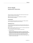
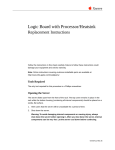
Figure 5-1. Screenshot of XServe Web Interface
On the main page you will see four tabs that represent the following four functions:
1. Health: provides health statistic report. The web page is created by XServe every minute.
User can browse three types of report: last minute report, last hour report and yesterday
report.
2. XSensor: User can use this function to view the real-time data. Before using this function,
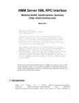
make sure xserve has started xml server already. That is ‘-xmlport=9002’ and one of ‘-xmlr’,
‘-xmlp’,’-xmlc’ must be turned on.
An example web page is shown in Figure 5-2.
Figure 5-2. Screenshot of XSensor Web Interface
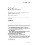
3. Command: The web interface provides the function to send commands to XServe. There are
three types of commands that are available: Power Management, Mote Configuration and
Actuation. An example web page is shown in Figure 5-3.
Doc.# 7430-0111-01 Rev. C
Page 35
XServe User’s Manual
Figure 5-3. Screenshot of Command Web Interface
In the web interface, all commands are end-to-end and hence Node ID and Group ID must be
specified.
4. Reprogram: provides XOtap interface. It supports Query, Boot and Download. An example
web page is shown in Figure 5-4.
Page 36
Doc.# 7430-0111-01 Rev. C
XServe User’s Manual
Figure 5-4. Screenshot of Command Web Interface
Doc.# 7430-0111-01 Rev. C
Page 37
XServe User’s Manual
6 Using Xserve Modbus Interface
6.1 Modbus Overview
The Modbus protocol was originally developed in 1978 to exchange information between
devices on a factory floor. Modbus has since become a fairly ubiquitous communication
mechanism in industrial environments, and is now the defacto standard for PLC systems.
Modbus devices communicate over a serial network in a master/slave (request/response)
relationship using one of two transmission modes: ASCII (American Standard Code for
Information Interchange) mode or RTU (Remote Terminal Unit) mode.
6.2 Modbus Message Structure
Modbus defines a standardized message structure that is independent of the type of physical
interface used. The same messages are used for example by Modbus over RS232 as on
Modbus/TCP over ethernet. This common interface definition allows Modbus messages from
legacy devices to be sent over an upgraded industrial network infrastructure, without the need for
large changes in the software. A device can also communicate with several Modbus nodes at
once, even if they are connected with different interface types, without the need to use a different
protocol for every connection.
On simple interfaces like RS485 or RS232, the Modbus messages are sent in plain form over the
network. In this case the network is dedicated to Modbus. When using more versatile network
systems like TCP/IP over ethernet, the Modbus messages are embedded in packets with the
format necessary for the physical interface. In that case Modbus and other types of connections
can co-exist at the same physical interface at the same time. Although the main Modbus message
structure is peer-to-peer, Modbus is able to function on both point-to-point and multihop
networks.
Each Modbus message has the same structure. Four basic elements are present in each message.
The sequence of these elements is the same for all messages, to make it easy to parse the content
of the Modbus message. A conversation is always started by a master in the Modbus network. A
Modbus master sends a message and—depending of the contents of the message—a slave takes
action and responds to it. There can be more masters in a Modbus network. Addressing in the
message header is used to define which device should respond to a message. All other nodes on
the Modbus network ignore the message if the address field doesn't match their own address.
Table 6-1. Modbus Message Structure
Field
Description
Device address
Address of the receiver
Function code
Code defining message type
Data
Data block with additional information
Error check
Numeric check value to test for communication errors
More details on Modbus interface is available at
http://www.modbus.org/
Page 38
Doc.# 7430-0111-01 Rev. C
XServe User’s Manual
http://modbus.control.com/
6.3 Using XServe Modbus Interface
XServe can store wireless sensor network data and make it available via a modbus interface.
When XServe runs with modbus mode enabled, XServe acts as a modbus slave. Thus sensor data
from the network can be queried from XServe directly by a modbus master via Modbus serial
protocol. Both RTU and ASCII serial protocols are supported.
XServe will provide a single, flat address register map of sensor values that can be queried over
the ModBus interface. The mapping of nodeid, sensor to offset is provided by the user in XML.
The format of this XML is described below.
To run Modbus in XServe, use
–m
or -m with options (items contained within the less than/greater than brackets <>)
-m=<COM port, baudrate, protocol type<RTU/ASCII>, slave address,
default register value>
When no extended options are passed with the -m flag, the following default settings will be
used: ‘/dev/ttyS2,9600,RTU,32,0’. If you run using arguments xserve -r -m or xserve -xmlr
-m, the parsed values will be stored into the modbus registers database; if run using arguments
xserve -c -m or xserve -xmlc -m the converted values will be stored into modbus registers
database.
To query the data in the mesh, the map from (nodeid, sensor) to modbus register should be
defined in a related xml config file. For example, to use modbus interface in an MTS310 XMesh
network, mapping from sensors to modbus registers should be defined in the
‘mts310_mesh_config.xml’ file as shown below. The value format of mapping is <modbus
register address, sensor type, nodeid>. The example below only supports 2 nodes;
node 0 and node 1, users can add more maps for other nodes as needed.
<XDataSink name="Generic Modbus Datasink">
<XDSParam name="Mapping1" value="1,voltage,0"/>
<XDSParam name="Mapping2" value="2,temp,0"/>
<XDSParam name="Mapping3" value="3,light,0"/>
<XDSParam name="Mapping4" value="4,accel_x,0"/>
<XDSParam name="Mapping5" value="5,accel_y,0"/>
<XDSParam name="Mapping6" value="6,mag_x,0"/>
<XDSParam name="Mapping7" value="7,mag_y,0"/>
<XDSParam name="Mapping8" value="8,mic,0"/>
<XDSParam name="Mapping9" value="9,voltage,1"/>
<XDSParam name="Mapping10" value="10,temp,1"/>
<XDSParam name="Mapping11" value="11,light,1"/>
<XDSParam name="Mapping12" value="12,accel_x,1"/>
Doc.# 7430-0111-01 Rev. C
Page 39
XServe User’s Manual
<XDSParam name="Mapping13" value="13,accel_y,1"/>
<XDSParam name="Mapping14" value="14,mag_x,1"/>
<XDSParam name="Mapping15" value="15,mag_y,1"/>
<XDSParam name="Mapping16" value="16,mic,1"/>
</XDataSink>
Page 40
Doc.# 7430-0111-01 Rev. C
XServe User’s Manual
7
7.1
Advanced Xserve Functionality
XServe Architecture
This section covers XServe architecture and defines the interfaces to extend XServe for
application specific requirements. XServe’s architecture consists of a core set of services, a
cross-platform portability layer, and a set of plug-in modules. The user can extend XServe by
developing an extension module in C as dynamically loaded library, or by supplying XML
Configuration files to define data parsers and configure a generic set of datasinks.
Forward / inject packets
to local cluster via port
9001
Serial
Process
Modules
Data Sinks
XSERVE
Timer Modules
Core
Process
Parsers
Event
Manager
Commands
Cross-platform Portability Layer (XPL)
Library
Timer Event
Process
Socket
Socket
Serial
Packet Data Flow
Parsed Data Flow
Figure 7-1. XServe Block Diagram
The XServe core services provide the following functionality:
y
Event Management—handles concurrent I/O. Processes serial and socket byte streams.
y
Process Monitor—starts all the process modules, monitors them, and restarts them if they die.
y
Serial Forwarder—virtualizes the mesh connections and supplies raw packets access to
clients.
The XServe higher level services fall into the following categories:
y
Parsers—extracts logical fields from a data packet and builds name / value pairs
y
Data Sinks—detects relevant name / value data rows and performs special handling
y
Command Modules—takes user command requests and injects correct packet into mesh
y
Task Modules—handles recurring events or timeouts
y
Process Modules—Provides services run, as external processes, and monitored by XServe.
Doc.# 7430-0111-01 Rev. C
Page 41
XServe User’s Manual
7.1.1
Event Management
XServe is an event based sytem. Service and modules register event handlers with the Event
Manager to be notified when certain events occur in the system. The Event Management service
is a core feature of XServe and is used by all incoming communication from the Mote Tier or
from enterprise applications.
7.1.2
Process Management
XServe relies on external processes to manage Web Services and Modbus communication.
These processes are started and monitored by the Process Management system. The XServe
processes itself is started as an external process and is monitored by the Process Management
system. If any of the processes under the Process Management system dies due to a system
error, an effort is made by the Process Management system to restart the process.
7.1.3
Serial Forwarder
At its core XServe provides basic routing services to the Mote network. As a serial forwarder
XServe allows enterprise applications to communicate directly with the Mote Tier. Applications
send and receive raw data directly to the mote network with no high level parsing, converting or
processing. XServe provides an unframed Serial Forwarder for enterprise applications to connect
to and can connect to either a framed or unframed Serial Forwarder to communicate with the
Mote Tier. For more information on Serial Forwarder protocol and the framed and unframed
link connection (see Section 13.2).
On the Mote Tier side, XServe can connect directly via a serial port, or it can connect indirectly
through another Serial Forwarder application. This functionality allows multiple XServe
instances to connect as a chain, for example, XServe acting as a Serial Forwarder can run directly
on a stargate while an instance of XServe running higher level services can run on a PC handling
data input from the XServe on the stargate.
On the enterprise application side, XServe provides an unframed Serial Forwarder server port.
Multiple enterprise applications can connect to XServe simultaneously and each will receive raw
data from the Mote Tier and will have the ability to send their own raw packet data through
XServe to the Mote Tier. When communicating with the Serial Forwarder, users should
remember that XServe sends and receive raw packet, with no extra processing done on the
packet. Packets sent to XServe toward the Mote Tier will be sent as is to the network.
7.1.4
Parsers
Parsers are the initial modules which handle data as it arrives from the Mote Tier. Parsers are
responsible for extracting data from the packet and constructing a set of name-value pairs for
entries in the packet. Only one Parser is responsible for parsing a given data packet. Each parser
contains a filter to determine whether it is responsible for parsing the given packet. An example
of typical filter could be:
if (AM_TYPE = 50) and (BOARD_ID = 89)
The first parser to match is then responsible for the packet. The parser splits the packet into
fields and groups these into a DataRow object which is then passed to other DataSink modules
Page 42
Doc.# 7430-0111-01 Rev. C
XServe User’s Manual
internally. When the parser builds a DataRow, it optionally sends the fields through unit
conversion depending on the command line arguments given by the user.
7.1.5
Datasinks
Datasinks are processing modules which take a Parsed DataRow and perform specialized
handling. The Datasink is free to do anything with the DataRow including modify it. Unlink
Parsers, where only one Parser is responsible for a packet, all Datasinks loaded into the system
have access to DataRow. Each Datasink contains a filter which determines at runtime whether it
will process a particular DataRow or not. XServe provides an initial set of Datasinks for
implementing printing data to the terminal screen, exporting packets to a file, logging data into a
database, and export data to an XML Stream.
7.1.6
Command Modules
XServe provides an XML RPC interface to allow enterprise applications to issue commands to
either the network or to XServe itself. Command modules are responsible for handling these
XML RPC events. Currently XCommand methods are implemented in XServe through the
Command Module interface.
7.1.7
Task Modules
Tasks represent modules which are scheduled to occur in periodic fashion. These can include
monitor services, accumulating statistics, or updating values. These tasks run independent of
packet arrival events. Currently the Report Server which displays HTML pages and statistics
runs as a Task Module.
7.1.8
Process Modules
Process modules are external process run by XServe to provide service. These processes are
managed by the Process Management system. Currently the HTTP Web Server and the Modbus
Communication process are both run as Process Modules.
7.2
Parsers
Parsers are implemented as dynamically loadable libraries which are loaded by XServe on start
up. XServe’s default action is to load all parsers from the Parser Library Directory. A subset of
parsers can be loaded using the –loadparsers startup flag (See Section 3.2.10). The Parser library
directory is set by default to “../lib/parsers” and assumes XServe is started from the directory in
which it is installed. The Parser Library Directory can be changed by setting the ParserLibDir
field in the Parameters File (See Section 7.4).
Users can extend XServe to parse their own packets in two ways
y
Creating a XML Configuration file
y
Building a C module using the Parser Dynamic Loadable Library Interface
Doc.# 7430-0111-01 Rev. C
Page 43
XServe User’s Manual
7.2.1
XML Configuration Parser
XML Configuration files define parsing rules for XServe’s Generic XML Configuration Parser.
The XML Configuration Parser internally constructs parsers from XML Configuration
documents allowing users to easily extend XServe to parse user specific packets.
XML Configuration files consist of 3 sections:
y
Field Definitions: Field Definitions map field names to portions of the data packet. They
also include conversion rules for fields that require conversion.
y
Filter Definitions: Filter Defintions construct logical statements which determine whether a
packet is to be parsed by this particular parsing configuration.
y
DataSink Parameters: Datasink Parameters define parser specific parameters for each
Datasink.
Below is a portion XML Configuration for a MTS300 data packet:
<?xml version="1.0" encoding="ISO-8859-1"?>
<!DOCTYPE XServeConfig SYSTEM "./xserve_config.dtd">
<XServeConfig>
<XFieldExtractor name="XMTS300 Multihop Config XML" order="3">
<XFields>
<XField name="amtype" byteoffset="2" length="1" type="uint8"/>
<XField name="nodeid" byteoffset="7" length="2" type="uint16" specialtype="nodeid"/>
<XField name="parent" byteoffset="14" length="2" type="uint16" specialtype="parentid"/>
<XField name="group" byteoffset="3" length="1" type="uint8"/>
<XField name="board_id" byteoffset="12" length="1" type="uint8" specialtype="boardid"/>
<XField name="packet_id" byteoffset="13" length="1" type="uint8"/>
<XField name="voltage" byteoffset="16" length="2" type="uint16">
<XConversion function="(1252352/x)" returntype="uint16">
<XConvParam variablename="x" fieldname="voltage" type="float"/>
</XConversion>
</XField>
<XField name="temp" byteoffset="18" length="2" type="uint16"/>
<XField name="light" byteoffset="20" length="2" type="uint16">
<XConversion function="(y * (1252352/x) / 1023)" returntype="uint16">
<XConvParam variablename="x" fieldname="voltage" type="float"/>
<XConvParam variablename="y" fieldname="light" type="uint16"/>
</XConversion>
</XField>
<XField name="mic" byteoffset="22" length="2" type="uint16"/>
</XFields>
…
</XFieldExtractor>
</XServeConfig>
Page 44
Doc.# 7430-0111-01 Rev. C
XServe User’s Manual
<XFieldExtractor>
The root document of any XML Configuration file is <XFieldExtractor>. Field Extractor
defines a single parser containing a set of fields, a filter, and any data sink parameters.
<XFieldExtractor name=NAME order=ORDER>
…….
</XFieldExtractor>
Table 7-1. XFieldExtractor Attributes
Attribute
Description
Required
name
The name of the XML Parser. XML Parser names
should be unique.
YES
order
DataRows are passed to Datasinks in a specified
order. The order is determined by the the order
attribute. Orders are sorted with lowest number being
first and highest number being last
YES
<XFields>
The root of the Field Definition section is the <XFields> tag. There is only <XFields> tag in
a Field Extractor and it contains all Field mapping definitions.
<XFields>
…….
</XFields>
<XField>
The <XField> tag defines a single name value pair mapping. The name value pairing is done by
assigning a portion of the bytes in the data packet to a name.
<XField name="light" byteoffset="20" length="2" type="uint16">
…
</XField>
Table 7-2. XField Attributes
Attribute
Description
Required
name
The name of the field. The name should be unique
within the Field Extractor.
YES
byteoffset
The position of the value of this field in the packet
relative to the beginning of the packet.
YES
length
The size of the value in bytes.
YES
type
The type of the field value. Possible values are:
•
byte
•
char
•
short
•
int
•
long
•
uint8
•
uint16
•
uint32
YES
Doc.# 7430-0111-01 Rev. C
Page 45
XServe User’s Manual
Attribute
Description
•
uint64
•
raw
•
string
•
float
•
double
Required
<XBitField>
The <XBitField> tag is a specialized version of the <XField> tag, allowing the user to extract
fields at the bit level granularity. This is useful for extracting information from a bit map or
extracting data from data which has been byte compressed.
For example, the Surge Application sends the voltage reference in the top 9 bits of a uint32 field
in the data packet. To extract the voltage reference from the 32 bit number we need to mask out
the top 9 bits and then shift the value over 23 bits. The <XBitField> allows users to define this
type of operational logic.
<XBitField name="vref" byteoffset="17" length="4" type="uint32" mask="0xFF800000" shift="23">
…
</XBitField>
Table 7-3. XBitField Attributes
Page 46
Attribute
Description
Required
Name
The name of the field. The name should be unique
within the Field Extractor.
YES
Byteoffset
The position of the starting byte in which the value of
the field is contained in the packet relative to the
beginning of the packet.
YES
Length
The size of the bytes containing the value of the field.
YES
Type
The type of the field value. Possible values are:
•
byte
•
char
•
short
•
int
•
long
•
uint8
•
uint16
•
uint32
•
uint64
•
raw
•
string
•
float
•
double
YES
mask
The hexadecimal mask over the bytes which will
extract the necessary bytes with a logical AND.
YES
shift
The number of bits to shift the resulting masked
value to position the value correctly
YES
Doc.# 7430-0111-01 Rev. C
XServe User’s Manual
<XConversion>
Each Field Definition maps the raw values from the packet to a named field. In most cases the
value in the packet is a hardware specific value and is not in a format which is understandable by
users or external applications. To handle this, each field definition tag can optionally contain a
<XConversion> tag which describes a mathematical equation to convert the raw values into a
user desired unit of measure. The equation can contain values from other fields in the packet
allowing complex equations. The values used for each field input into the equation are the raw
value pulled from the data packet.
For example a light reading from a sensor packet requires convertion from its raw resistance
value to a unit of conversion appropriate for light (mV). Below is the necessary equation:
Light(mV) = (( (light_value) * (1252352/(voltage_value)) / 1023)* 4)
The equation takes both the light reading in the packet and the voltage value in the packet to
convert it to the correct unit of measure.
<XField name="light" byteoffset="21" length="1" type="uint8">
<XConversion function="((y * (1252352/x) / 1023)* 4)" returntype="uint16">
<XConvParam variablename="x" fieldname="vref" type="float"/>
<XConvParam variablename="y" fieldname="light" type="uint8"/>
</XConversion>
</XField>
Table 7-4. XConversion Attributes
Attribute
Description
Required
function
The mathematical equation required to convert the
value to its appropriate unit of measure
YES
returntype
The type of the field value after conversion.
Possible values are:
•
byte
•
char
•
short
•
int
•
long
•
uint8
•
uint16
•
uint32
•
uint64
•
raw
•
string
•
float
•
double
YES
<XConversionParam>
The <XConversionParam> tag maps the variable in the function to a field name in the actual
parser. This allows users to build generic equations to use over and over and then map the actual
variables differently in each conversion function.
Doc.# 7430-0111-01 Rev. C
Page 47
XServe User’s Manual
Table 7-5. XConversionParam Attributes
Attribute
Description
Required
variablename
The variable name in the equation which needs to be
mapped to a field
YES
Fieldname
The field name which is mapped to the variable in the
equation
YES
type
The type the field’s raw value needs to be cast to
when in the equation.
Possible values are:
•
byte
•
char
•
short
•
int
•
long
•
uint8
•
uint16
•
uint32
•
uint64
•
raw
•
string
•
float
•
double
YES
<XFilter>
Each Field Definition defines a parser for a particular type of packet. The <XFilter> tag
defines a filter which is used by XServe to determine whether a particular packet should be
parsed by this Field Definition. The XFilter is a set of logical operations on a set of conditions.
The available logical operations are AND, OR, and NOT. The logical operations can be nested
if required.
The MTS310 sensor board parser should only be used to parse a data packet based on the
following logic:
(AMTYPE == 0x31 OR AMTYPE==0x33) AND BOARDID==0x83
<XFilter>
<XCondAnd>
<XCondOr>
<XCond name="IsEqual">
<XFilterParam name="fieldname" value="amtype"/>
<XFilterParam name="fieldvalue" value="0x31"/>
</XCond>
<XCond name="IsEqual">
<XFilterParam name="fieldname" value="amtype"/>
<XFilterParam name="fieldvalue" value="0x33"/>
</XCond>
</XCondOr>
<XCond name="IsEqual">
Page 48
Doc.# 7430-0111-01 Rev. C
XServe User’s Manual
<XFilterParam name="fieldname" value="board_id"/>
<XFilterParam name="fieldvalue" value="0x83"/>
</XCond>
</XCondAnd>
</XFilter>
<XCondAnd>
<XCondOr>
<XCondNot>
<XCond>
The <XCond> tag defines the name of the condition you wish to test. Currently the only condition
available is the IsEqual condition for a fieldname and a value. The IsEqual condition takes the
fieldname and the fieldvalue as its parameters.
Table 7-6. XCond Attributes
Attribute
Description
Required
name
The name of the condition. Available conditions are:
•
IsEqual
YES
<XFilterParam>
The <XFilterParam> defines the parameters to each condition.
Table 7-7. XFilerParam Attributes
Attribute
Description
Required
name
The name of the parameter to pass into the filter
YES
value
The value of the named parameter to pass into the
filter.
YES
<XDataSinks>
Each parser can pass its own parameters into a DataSink to configure the data sink specifically
for that packet type. More information on the DataSink parameter configuration is available in
Section 7.3.
<XDataSinks>
<XDataSink name="Generic Print Datasink">
<XDSParam name="printstring"
\
value="SURGE [sensor data converted to engineering units]:\n
health:
node id=%s
parent=%s
temperature = %s degC\n
AccelY: = %s g\n
MagX:
seq_no=%s\n
light:
battery
= %s ADC mv\n
= %s mgauss, MagY:
= %s mv\n
AccelX:
= %s g,
= %s mgauss "/>
<XDSParam name="printfields" \
value="nodeid,parent,epoch,vref,thermistor,light,accelX,accelY,magX,magY"/>
</XDataSink>
Doc.# 7430-0111-01 Rev. C
Page 49
XServe User’s Manual
Table 7-8. XDataSinks Attributes
Attribute
Description
Required
name
The name of the data sink to be configured.
YES
<XDSParams>
The <XDSParam> defines the parameters to each datasink.
Table 7-9. XDSParams Attributes
7.2.2
Attribute
Description
Required
Name
The name of the parameter to pass into the
datasink
YES
value
The value of the named parameter to pass into the
datasink
YES
Parser Dynamic Loadable Library Interface
The Parser Dynamic Loadable Library (PDLL) Interface is useful for application with complex
parsing needs which cannot be met by an XML Configuration file. The PDLL Interface allows
users to build their own C-based parsers and compile them to Dynamically Loaded Libraries
(DLL). Once built, the parser can be placed in the Parser Library Directory to be loaded by
XServe for usage.
The PDLL Interface comprises of 3 components:
1. An initialization function
2. A pair of filter and parse callback functions
3. A callback registration structure
7.2.2.1 Initialization Function
The initialization function is called after the parser has been loaded into XServe. Any
initialization procedures and checks should be done in this function. At a minimum the
initialization function should register the parser callbacks through the callback registration
structure. The method signature of the initialization function is below:
void initialize_parser()
7.2.2.2 Callback Functions
The parser callback interface contains two functions. The filter function takes the raw packet
from the Mote Tier and determines if the given parser is responsible for parsing the packet. The
parse function is responsible for converting the raw packet into a DataRow. The DataRow is
XServe data structure which contains the named value pairs of the parsed data and any converted
values. Both the filter and parse method can have any unique name. They are called via a
function pointer passed in with callback registration structure so the exact method names are
unimportant.
The signature for the filter function is provided below:
int filter(unsigned char* buffer, int length,XServeParams* xparams)
Page 50
Doc.# 7430-0111-01 Rev. C
XServe User’s Manual
Arguement
Description
buffer
The raw data packet as a character byte array.
length
The length the character byte array passed into the function
xparams
The XServeParams structure contains the initial command line
arguments passed in. It allows the library to parse the command line
arguments looking for library specific values.
Return Value
The filter returns 1 if is responsible for parsing the packet and returns 0 if
it not responsible for parsing the packet.
The signature for the parse function is provided below:
XDataRow* parser(unsigned char* buffer, int length,XServeParams* xparams)
Arguement
Description
buffer
The raw data packet as a character byte array.
length
The length the character byte array passed into the function
xparams
The XServeParams structure contains the initial command line
arguments passed in. It allows the library to parse the command line
arguments looking for library specific values.
Return Value
The parser returns a pointer to XDataRow structure.
7.2.2.3 Callback Registration Structure
The callback registration structure registers the parser and its callback functions with XServe.
Unless the parser is registered XServe will not use it. The callback registration structure looks as
follows:
typedef struct XParseHandler {
char*
name;
char*
version;
int rank;
PacketParseFilter filter;
PacketParser parser;
} XParseHandler;
Field
Description
Name
The display name of the parser
Version
The version information of the parser
Rank
The ordered rank of the parser. Parsers are called in relative order to
determine if they are responsible for parsing a packet.
filter
The function pointer to the parsers filter function
Parser
The function pointer to the parsers parse function
To register all callback registration structure the parser should call the following function:
void xparse_register_handler(XParseHandler *handler)
Doc.# 7430-0111-01 Rev. C
Page 51
XServe User’s Manual
7.3
Data Sinks
Like Parsers, Data Sinks are implemented as dynamically loadable libraries which are loaded by
XServe on start up. XServe’s default action is to load all parsers from the DataSink Library
Directory. A subset of data sinks can be loaded using the –loaddatasinks startup flag (See
Section 3.2.10). The DataSink Library Directory is set by default to “../lib/datasinks” and
assumes XServe is started from the directory in which it is installed. The DataSink Library
Directory can be changed by setting the DataSinkLibDir field in the Parameters File (See Section
7.4).
Users can extend XServe to add their own datasink processing by building a C module using the
Datasink Dynamic Loadable Library Interface or users can configure provided datasinks using
XML Configuration files.
7.3.1
XML Configuration Generic Datasinks
XServe provides a set of Generic Datasinks which can be configured by an XML Configuration
file. The list of provided Datasinks is follows:
• Generic Print Datasink
• Generic File Datasink
• Generic Simple XML Datasink
• Generic Alert Datasink
• Open Log Datasink
• Heartbeat Datasink
7.3.1.1 Generic Print Datasink
The Generic Print DataSink displays data on the terminal screen. The layout and the fields
displayed on the screen for each packet are configurable using a XML Configuration file.
<XDataSink name="Generic Print Datasink">
<XDSParam name="printstring"
\
value="SURGE [sensor data converted to engineering units]:\n
health:
node id=%s
parent=%s
temperature = %s degC\n
AccelY: = %s g\n
MagX:
seq_no=%s\n
light:
battery
= %s ADC mv\n
= %s mgauss, MagY:
= %s mv\n
AccelX:
= %s g,
= %s mgauss "/>
<XDSParam name="printfields" \
value="nodeid,parent,epoch,vref,thermistor,light,accelX,accelY,magX,magY"/>
</XDataSink>
The Generic Print Datasink takes the following parameters.
Table 7-10. Generic Print DataSink Parameters
Page 52
Parameter
Description
Required
printstring
This is a template string which will format the
display out to screen. Each % value will be
filled in with the corresponding field value
YES
Doc.# 7430-0111-01 Rev. C
XServe User’s Manual
The print fields are the name of the fields
whose value will replace each % in the
printstring template. Each % is replaced with
a field in order.
printfields
YES
7.3.1.2 Generic File Datasink
The Generic File Datasink outputs data to a specified file. The field delimator, the header, and
the file name are all configurable by a XML Configuration file.
<XDataSink name="Generic File Datasink">
<XDSParam name="rawfilename" value="/opt/tinyos-1.x/raw_surge_data.txt"/>
<XDSParam name="parsedfilename" value="/opt/tinyos-1.x/parsed_surge_data.txt"/>
<XDSParam name="convertedfilename" value="/opt/tinyos-1.x/converted_surge_data.txt"/>
<XDSParam name="delim" value=","/>
<XDSParam name="header" value="yes"/>
</XDataSink>
The Generic File DataSink takes the following paramteres.
Table 7-11. Generic File DataSink Parameters
Parameter
Description
Required
rawfilename
The filename where raw
data output is written
NO
(If the parameter is not given then
no raw data will be written to file)
parsedfilename
The filename where
parsed data output is
written.
NO
(If the parameter is not given then
no parsed data will be written to
file)
convertedfilename
The filename where
converted data output is
written.
NO
(If the parameter is not given then
no converted data will be written to
file)
Delim
The delimator to be used
to separate field names
NO
(The default value is ‘,’)
Header
A Boolean indicating
whether the file should
have a header
NO
(The default value is ‘yes’)
7.3.1.3 Generic Simple XML Datasink
The Generic Simple XML Datasink is responsible for printing an XML stream for each data
packet. The Generic Simple XML Datasink is not configurable by XML but can be configured
by two command line inputs –xmlfile and –xmlport (See Section 3.2.7)
<?xml version="1.0" ?>
<MotePacket>
<RawPacket>0x7E00117D16000000000000000000007E00060000BEC07A60798E74</RawPacket>
<ParsedDataElement>
Doc.# 7430-0111-01 Rev. C
Page 53
XServe User’s Manual
<Name>amtype</Name>
<RawValue>0x11</RawValue><ConvertedValue>17</ConvertedValue>
</ParsedDataElement>
<ParsedDataElement>
<Name>nodeid</Name>
<RawValue>0x00</RawValue><ConvertedValue>0</ConvertedValue>
</ParsedDataElement>
<ParsedDataElement>
<Name>parent</Name>
<RawValue>0x7e</RawValue><ConvertedValue>126</ConvertedValue>
</ParsedDataElement>
<ParsedDataElement>
<Name>vref</Name>
<RawValue>0x017c</RawValue><ConvertedValue>3295</ConvertedValue>
</ParsedDataElement>
<ParsedDataElement>
<Name>epoch</Name>
<RawValue>0x0006</RawValue><ConvertedValue>6</ConvertedValue>
</ParsedDataElement>
<ParsedDataElement>
<Name>light</Name>
<RawValue>0xc0</RawValue><ConvertedValue>2474</ConvertedValue>
</ParsedDataElement>
<ParsedDataElement>
<Name>thermistor</Name>
<RawValue>0x7a</RawValue><ConvertedValue>23.045807</ConvertedValue>
</ParsedDataElement>
<ParsedDataElement>
<Name>magX</Name>
<RawValue>0x60</RawValue><ConvertedValue>51.857669</ConvertedValue>
</ParsedDataElement>
<ParsedDataElement>
<Name>magY</Name>
<RawValue>0x79</RawValue><ConvertedValue>65.362270</ConvertedValue>
</ParsedDataElement>
<ParsedDataElement>
<Name>accelX</Name>
<RawValue>0x8e</RawValue><ConvertedValue>2360.000000</ConvertedValue>
</ParsedDataElement>
<ParsedDataElement>
<Name>accelY</Name>
<RawValue>0x74</RawValue><ConvertedValue>280.000000</ConvertedValue>
Page 54
Doc.# 7430-0111-01 Rev. C
XServe User’s Manual
</ParsedDataElement>
</MotePacket>
The XML stream output by this datasink can provide the raw packet, the parsed values, and the
converted values.
<MotePacket>
This tag denotes a logical block that contains data from a single packet from a single
mote.
<RawPacket>
This tag carries the entire packet as a raw hex encoded in ASCII starting with 0x.
<ParsedDataElement>
This tag denotes a logical block that contains information about one parsed field of data.
Including RawValue or ConvertedValue.
<ConvertedDataElement>
This tag denotes a logical block that contains information about one converted field of
data.
<Name>
This tag carries the name of a field.
<RawValue>
This tag carries the raw value for a field.
<ConvertedValue>
This tag carries the converted value for a field.
7.3.1.4 Generic Alert Datasink
The Generic Alert DataSink defines a set of bounds on a particular value. The datasink can alert
users on the terminal screen and in the log file a particular packes values have deviated from an
acceptable range. The bound for each data value can set in an XML Configuration file.
<XDataSinks>
<XDataSink name="Generic Alert Datasink">
<XDSParam name="voltage" value="[2500,3500]"/>
<XDSParam name="humid" value="[0,100]"/>
<XDSParam name="humtemp" value="[-5,45]"/>
<XDSParam name="prtemp" value="[-5,45]"/>
<XDSParam name="press" value="[900,1100]"/>
<XDSParam name="accel_x" value="[-2000,2000]"/>
<XDSParam name="accel_y" value="[-2000,2000]"/>
<XDSParam name="taoch0" value="[0,500]"/>
</XDataSink>
</XDataSinks>
Doc.# 7430-0111-01 Rev. C
Page 55
XServe User’s Manual
Table 7-12. Generic Alert DataSink Parameters
Parameter
Description
Required
Name
This is the name of the field to be bound
YES
values
This is the data bound on the converted value
in the fomat: [lower,upper]
YES
7.3.1.5 Open Log DataSink
The Open Log Datasink is responsible for logging data packets to a database. Currently the only
database supported by XServe is the PostgreSQL database. To configure the connection
parameters of the PostgreSQL database, use the –dbserver, -dbport, -dbname, -dbuser, dbpassword command line parameters.
The Open Log Datasink allows users to create tables, define rules on table, define insert
statements and define update statements.
<XDataSink name="Open Log Datasink">
<XDSParam name="tablename_1" value="mts300_results"/>
<XDSParam name="createsql_1"
value="CREATE TABLE mts300_results ( result_time timestamp without time
zone,epoch integer, nodeid integer, parent integer,voltage
integer, temp integer, light integer)"/>
<XDSParam name="tablename_2" value="mts300_results_l"/>
<XDSParam name="createsql_2"
value="CREATE TABLE mts300_results_l ( result_time timestamp without
time zone,epoch integer, nodeid integer, parent integer,voltage
integer, temp integer, light integer)"/>
<XDSParam name="rulesql_2"
value="CREATE RULE cache_mts300_results AS ON INSERT TO mts300_results
DO ( DELETE FROM mts300_results_l WHERE nodeid = NEW.nodeid;
INSERT INTO mts300_results_l VALUES (NEW.*); )"/>
<XDSParam name="insertsql_2"
value="INSERT into mts300_results (result_time, nodeid,parent, voltage,
temp, light) values (now(),%i,%i,%i,%i,%i)"/>
<XDSParam name="insertfields_2" value="nodeid,parent,voltage,temp,light"/>
</XDataSink>
Table 7-13. Generic Log DataSink Parameters
Page 56
Parameter
Description
Required
tablename
This is the name of the database table
packet data will be sent to. The datasink
uses the table name to check the
existence of the table.
YES
createsql
This is the sql string which will be
executed if no table with the given
tablename is found in the database
NO
(If the parameter is not given then
the datasink will not create a table
if the table name does not exist
Doc.# 7430-0111-01 Rev. C
XServe User’s Manual
and will not attempt to
insert/update the given row)
rulesql
This is sql which will used with the create
sql to define any rules on the table
NO
insertsql
This is the insert sql statement which will
be executed to insert the row into the
database table
NO
(If the parameter is not given then
no inserts will be performed)
insertfields
Thevalues of the field names listed in
insertfields will replace the % in the
insertsql in the order they are listed.
YES if an insertsql statement is
given. NO otherwise.
updatesql
The update sql statement which will be
executed to update the database table
NO
(If the parameter is not given then
no updates will be perfomed)
updatefields
Thevalues of the field names listed in
updatefields will replace the % in the
updatesql in the order they are listed.
YES if an updatesql statement is
given. NO otherwise.
When logging a data packet into a database it may be necessary to execute multiple insert and
update statements over multiple tables. The Open Log Datasink manages this by grouping
statements together using the “_#” format in the parameter names. All ‘_#’ names are grouped
together and groups are executed in the order of their #.
7.3.1.6 Heartbeat Datasink
The base station is the most critical component in a sensor network since it is the entry point of
all data. To guarantee the base station is working correctly XServe provides a monitoring tool to
monitor whether the base station is functioning properly. It does this by monitoring heartbeat
packets from the base station.
The heartbeat data sink insures proper operation of the base station by setting a timeout for a
heartbeat packet. If a configured number of heartbeats are not sent by the base station, the
heartbeat module resets the base station (MIB510) and/or alerts the user that the base station is
not responding. Users can set these parameters using the –hearbeat command line parameter.
; NOTE: Instructions for setting the base station to emit hearbeat packets are available in the XMesh
User’s Manual.
7.3.2
Datasink Dynamic Loadable Library Interface
The Datasink Dynamic Loadable Library (DDLL) Interface is useful for user defined post
processing not provided by an existing Datasink. The DDLL Interface allows users to build their
own C-based datasinks and compile them to Dynamically Loaded Libraries (DLL). Once built,
the datasink can be placed in the Datasink Library Directory to be loaded by XServe for usage.
The DDLL Interface comprises of 3 components:
y
An initialization function
y
A pair of filter and process callback functions
y
A callback registration structure
Doc.# 7430-0111-01 Rev. C
Page 57
XServe User’s Manual
7.3.2.1 Initialization Function
The initialization function is called after the datasink has been loaded into XServe. Any
initialization procedures and checks should be done in this function. At a minimum, the
initialization function should register the datasink callbacks through the callback registration
structure. The method signature of the initialization function is below:
void initialize_datasink()
7.3.2.2 Callback Functions
The datasink callback interface contains two functions. The filter function takes the XDataRow
from the parser and determines if the given datasink is responsible for processing the packet.
The process function is responsible for doing any user defined processing with the DataRow.
The DataRow is XServe data structure which contains the named value pairs of the parsed data
and any converted values. Both the filter and process method can have any unique name. They
are called via a function pointer passed in with callback registration structure so the exact
method names unimportant.
The signature for the filter function is below:
int filter(XDataRow* row, XServeParams* xparams){
Arguement
Description
Row
The Data Row created from the parser
xparams
The XServeParams structure contains the initial command line
arguments passed in. It allows the library to parse the command line
arguments looking for library specific values.
Return Value
The filter returns 1 if is responsible for processing the packet and returns
0 if it not responsible for processing the packet.
The signature for the process function is below:
void process(XDataRow* row, XServeParams* xparams){
Arguement
Description
Row
The Data Row created from the parser
xparams
The XServeParams structure contains the initial command line
arguments passed in. It allows the library to parse the command line
arguments looking for library specific values.
7.3.2.3 Callback Registration Structure
The callback registration structure registers the datasink and its callback functions with XServe.
Unless the datasink is registered XServe will not use it. The callback registration structure looks
as follows:
typedef struct _XStoreHandler {
char*
name;
char*
version;
int rank;
PacketStoreFilter filter;
PacketStore process;
Page 58
Doc.# 7430-0111-01 Rev. C
XServe User’s Manual
} XStoreHandler;
Table 7-14. Callback Registration Fields
Field
Description
Name
The display name of the parser
Version
The version information of the parser
Rank
The ordered rank of the parser. Parsers are called in relative order to
determine if they are responsible for parsing a packet.
filter
The function pointer to the datasinks filter function
process
The function pointer to the datasink parse function
To register all callback registration structure the parser should call the following function:
void xstore_register_handler(XStoreHandler* handle)
7.4
Properties Files
XServe requires various external files to operate correctly. By default XServe assumes that it has
been started from the installation directory and that all pertinent files are located as installed. In
some cases users may like to move XServe to run from any directory. In these cases XServe will
require a pointer to the location of the necessary external files.
The pointer to these necessary files resides in properties files. XServe looks for the location of
this properties file by checking the environment variable XSERVER_PARAMETER_FILE. If the
environment variable is not found then XServe will assume it is running from the installation
directory and will look for files relative to that location. For example:
XSERVE_PARAMETER_FILE=/opt/MoteWorks/tools/xserve/bin/xparams.properties
The properties file must contain the following parameters.
Table 7-15. Properties Files Parameters
Property
Description
ConfigXMLDir
The directory where the XML Configuration files are located
ParserLibDir
The directory where the parsers are located
DataSinkLibDir
The directory where the datasinks are located
CommandLibDir
The directory where the command modules are located
XServeWebDir
The location where XServe web files are located
XServeLodDir
The location log files should be written
Doc.# 7430-0111-01 Rev. C
Page 59
XServe User’s Manual
8 Appendix A: Mote Packet Reference
This section details the packet formats for MoteWorks sensor applications.
8.1
TinyOS Header
All TinyOS packets share the following Active Message header.
Bytes: 2
1
1
1
Variable
Destination
Address
AM Type
AM Group
Length
Data Payload
TinyOS Header
8.1.1
Data Fields
The TinyOS header has the following fields:
Table 8-1 Header contents of a TinyOS message
8.2
Type
Field Name
Description
uint16_t
addr
Single hop destination address
uint8_t
type
Active message type
uint8_t
group
Active message group ID
uint8_t
length
Length of entire message
XMesh Header
Any packet delivered over XMesh contains the following multi-hop header.
Bytes: 5
2
2
2
1
Variable
TinyOS
Header
Source
Address
Origin
Address
Sequence
Number
Application
ID
Data Payload
XMesh Header
8.2.1
Data Fields
The XMesh multihop header has the following fields:
Table 8-2 Header contents of an XMesh message
Page 60
Type
Field Name
Description
uint16_t
sourceaddr
Single hop sender address
uint16_t
originaddr
Node ID of originator of message
int16_t
seqno
Sequence number for link estimation
uint8_t
socket
Application ID
Doc.# 7430-0111-01 Rev. C
XServe User’s Manual
8.3
XSensor Header
All XSensor applications have the XSensor header.
Bytes: 5
0/7
1
1
2
Variable
TinyOS
Header
XMesh
Header
Sensor Board
ID
Sensor
Packet ID
Parent
Data Payload
XSensor Header
8.3.1
Sensor Board ID
This field identifies uniquely which sensor board sent the packet and how the sensor readings are
organized in the subsequent payload.
Table 8-1 XSensor sensor board id for all data acquisition boards and sensor boards
Sensor Board
Model Number
Board
ID (Hex)
Board ID
(Decimal)
MTS101
0x82
130
MTS300
0x83
131
Buzzer, photoresistor, acoustic microphone, and thermistor
Description
External analog sensor inputs (6 to 10 bit ADCs), photoresistor, and
thermistor.
MTS310
0x84
132
Accelerometer (2-axis), buzzer, photoresistor, acoustic microphone,
magnetometer (2-axis), and thermistor.
MTS400
0x85
133
Accelerometer (2-axis), barometer (built-in ADC), pPhoto-sensitive
light, relative humidity and temperature (built-in 12 bit ADC).
MTS420
0x86
134
Accelerometer (2-axis), barometer (built-in ADC), GPS module,
photosynthetic light, relative humidity and temperature (built-in 12
bit ADC).
MDA300
0x81
129
External analog sensor Inputs (10 to 12 bit ADCs), relative humidity
and temperature (built-in 12 bit ADC), and relays (normally open
and normall closed).
MTS510
0x02
2
Accelerometer (2-axis), photo sensor, microphone.
MDA500
0x01
1
External analog and digital inputs
MEP510
0x04
4
Mote Environmental Package – temperature, relative humidity,
MICA2DOT
MEP410
0x8A
138
Mote Environmental Package – temperature, relative humidity,
pressure, photosynetic light (two), broadband light (two), MICA2
MDA320
0x90
139
External analog sensors(10 to 12 bit ADCs), built-in 16-bit ADC,
digital inputs, and relays (normally open and normall closed)/
MDA100
0x91
140
External analog sensor inputs (6 to 10 bit ADCs), photoresistor, and
thermistor.
MSP410
0xA0
160
Sense and respond reference board – MTS400 sensor set plus
PIR, microphone, beeper, two relays, two analog inputs, 2 general
purpose digital input/output
Doc.# 7430-0111-01 Rev. C
Page 61
XServe User’s Manual
8.4
CRC
The packet ends with a CRC that is calculated on the entire packet excluding the packet header
and the CRC field itself. A CRC is calculated by XORing the current byte with a shifted CRC
accumulator. The CRC is always 2 bytes. The code to calculate a CRC follows:
uint16_t xcrc_byte(uint16_t crc, uint8_t b)
{
uint8_t i;
crc = crc ^ b << 8;
i = 8;
do
if (crc & 0x8000)
crc = crc << 1 ^ 0x1021;
else
crc = crc << 1;
while (--i);
return crc;
}
int xcrc_calc(char *packet, int index, int count) {
int crc = 0;
while (count > 0) {
crc = xcrc_byte(crc, packet[index++]);
count--;
}
return crc;
}
Page 62
Doc.# 7430-0111-01 Rev. C
XServe User’s Manual
9
Appendix B: Sensor Packet Reference
The Table 9-1 shows a list of sensor and data acquisition boards (MTS and MDA Series) that are
supported by XServe.
Table 9-1 Sensor and Data Acquisition Boards supported by XServe
Sensor board
model number
Description
MTS101
External analog sensor inputs (6 to 10 bit ADCs), photoresistor, and thermistor.
MTS300
Buzzer, photoresistor, acoustic microphone, and thermistor
MTS310
Accelerometer (2-axis), buzzer, photoresistor, acoustic microphone, magnetometer (2axis), and thermistor.
MTS400
Accelerometer (2-axis), barometer (built-in ADC), pPhoto-sensitive light, relative
humidity and temperature (built-in 12 bit ADC).
MTS420
Accelerometer (2-axis), barometer (built-in ADC), GPS module, photosynthetic light,
relative humidity and temperature (built-in 12 bit ADC).
MDA300
External analog sensor Inputs (10 to 12 bit ADCs), relative humidity and temperature
(built-in 12 bit ADC), and relays (normally open and normall closed).
MTS510
Accelerometer (2-axis), photo sensor, microphone.
MDA500
External analog and digital inputs
MEP510
Mote Environmental Package – temperature, relative humidity, MICA2DOT
MEP410
Mote Environmental Package – temperature, relative humidity, pressure, photosynetic
light (two), broadband light (two), MICA2
MDA320
External analog sensors(10 to 12 bit ADCs), built-in 16-bit ADC, digital inputs, and
relays (normally open and normall closed)/
MDA100
External analog sensor Inputs (6 to 10 bit ADCs), photoresistor, and thermistor.
MSP410
Sense and respond reference board – MTS400 sensor set plus PIR, microphone,
beeper, two relays, two analog inputs, 2 general purpose digital input/output
9.1
MTS101
The MTS101 sensor board has a precision thermistor, light sensor/photocell, and general
prototyping area. It is used with the MICAz and MICA2 Motes.
9.1.1
Packet Structure
Bytes: 5
0/7
4
2
2
2
10
2
TinyOS
Header
XMesh
Header
XSensor
Header
Voltage
Thermistor
Light
…
CRC
MTS101 Payload
9.1.2
Data Fields
The MTS101 packet has the following fields:
Doc.# 7430-0111-01 Rev. C
Page 63
XServe User’s Manual
Table 9-2 Data Payload contents of MTS101 Packet
Type
Field Name
Description
uint16_t
voltage
Battery reading (also known as vref or voltage)
uint16_t
thermistor
Thermistor sensor reading
uint16_t
Light
Light sensor reading.
uint16_t
Adc0
Analog to Digital Converter reading
uint16_t
Adc1
Analog to Digital Converter reading
uint16_t
Adc2
Analog to Digital Converter reading
uint16_t
Adc3
Analog to Digital Converter reading
uint16_t
Adc4
Analog to Digital Converter reading
9.1.3
XML Packet Description
<?xml version="1.0" encoding="ISO-8859-1"?>
<!DOCTYPE XServeConfig SYSTEM "./xserve_config.dtd">
<XServeConfig>
<XFieldExtractor name="XMTS101 Multihop Config XML" order="3">
<XFields>
<XField name="amtype" byteoffset="2" length="1" type="uint8"/>
<XField name="nodeid" byteoffset="7" length="2" type="uint16"
specialtype="nodeid"/>
<XField name="parent" byteoffset="14" length="2" type="uint16"
specialtype="parentid"/>
<XField name="group" byteoffset="3" length="1" type="uint8"/>
<XField name="board_id" byteoffset="12" length="1" type="uint8"
specialtype="boardid"/>
<XField name="packet_id" byteoffset="13" length="1" type="uint8"/>
<XField name="voltage" byteoffset="16" length="2" type="uint16"/>
<XField name="temp" byteoffset="18" length="2" type="uint16"/>
<XField name="light" byteoffset="20" length="2" type="uint16"/>
<XField name="adc0" byteoffset="22" length="2" type="uint16"/>
<XField name="adc1" byteoffset="24" length="2" type="uint16"/>
<XField name="adc2" byteoffset="26" length="2" type="uint16"/>
<XField name="adc3" byteoffset="28" length="2" type="uint16"/>
<XField name="adc4" byteoffset="30" length="2" type="uint16"/>
</XFields>
</XFilter>
</XDataSinks>
</XFieldExtractor>
</XServeConfig>
Page 64
Doc.# 7430-0111-01 Rev. C
XServe User’s Manual
; NOTE: For details on the field convertion for a given sensor, see Appendix C.
9.1.4
XML Data Output
<?xml version="1.0" ?>
<MotePacket>
<RawPacket>0x7E00337D1B0000000000000082817E007D011D02E2015D01FF00E400F0000D01</RawPacket>
<ParsedDataElement>
<Name>amtype</Name>
<RawValue>0x33</RawValue>
<ConvertedValue>51</ConvertedValue>
</ParsedDataElement>
<ParsedDataElement>
<Name>nodeid</Name>
<RawValue>0x00</RawValue>
<ConvertedValue>0</ConvertedValue>
</ParsedDataElement>
<ParsedDataElement>
<Name>parent</Name>
<RawValue>0x7e</RawValue>
<ConvertedValue>126</ConvertedValue>
</ParsedDataElement>
<ParsedDataElement>
<Name>group</Name>
<RawValue>0x7d</RawValue>
<ConvertedValue>125</ConvertedValue>
</ParsedDataElement>
<ParsedDataElement>
<Name>board_id</Name>
<RawValue>0x82</RawValue>
<ConvertedValue>130</ConvertedValue>
</ParsedDataElement>
<ParsedDataElement>
<Name>packet_id</Name>
<RawValue>0x81</RawValue>
<ConvertedValue>129</ConvertedValue>
</ParsedDataElement>
<ParsedDataElement>
<Name>voltage</Name>
<RawValue>0x17d</RawValue>
<ConvertedValue>3287</ConvertedValue>
</ParsedDataElement>
<ParsedDataElement>
Doc.# 7430-0111-01 Rev. C
Page 65
XServe User’s Manual
<Name>temp</Name>
<RawValue>0x21d</RawValue>
<ConvertedValue>27.440985</ConvertedValue>
</ParsedDataElement>
<ParsedDataElement>
<Name>light</Name>
<RawValue>0x1e2</RawValue>
<ConvertedValue>1548</ConvertedValue>
</ParsedDataElement>
<ParsedDataElement>
<Name>adc0</Name>
<RawValue>0x15d</RawValue>
<ConvertedValue>349</ConvertedValue>
</ParsedDataElement>
<ParsedDataElement>
<Name>adc1</Name>
<RawValue>0xff</RawValue>
<ConvertedValue>255</ConvertedValue>
</ParsedDataElement>
<ParsedDataElement>
<Name>adc2</Name>
<RawValue>0xe4</RawValue>
<ConvertedValue>228</ConvertedValue>
</ParsedDataElement>
<ParsedDataElement>
<Name>adc3</Name>
<RawValue>0xf0</RawValue>
<ConvertedValue>240</ConvertedValue>
</ParsedDataElement>
<ParsedDataElement>
<Name>adc4</Name>
<RawValue>0x10d</RawValue>
<ConvertedValue>269</ConvertedValue>
</ParsedDataElement>
9.1.5
Print Raw
[2005/12/19 12:29:04] 7E 00 33 7D 1B 00 00 00 00 00 00 00 82 81 7E 00 7D 01 1D 02 E2 01 5D 01 FF
00 E4 00 F0 00 0D 01
Page 66
[32]
Doc.# 7430-0111-01 Rev. C
XServe User’s Manual
9.1.6
Print Parsed
[2005/12/19 12:32:41] MTS101 [sensor data converted to engineering units]:
health:
node id=0x00
tempurature: =0x21d
battery:
= 0x17d
light: = 0x1e2
adc0 = 0x15d mv adc1 = 0xff adc2 = 0xe4
adc3 = 0xf0 mv adc4 = 0x10d
9.1.7
Print Converted
[2005/12/19 13:33:50] MTS101 [sensor data converted to engineering units]:
health:
node id=0
battery:
tempurature: =27.440985 degC
= 3287 mv
light: = 1548 mv
adc0 = 349 mv adc1 = 255 mv adc2 = 228 mv
adc3 = 240 mv adc4 = 269 mv
9.1.8
XMTS101 Logging Output
INSERT into mts101_results (result_time,nodeid,parent,voltage,temp,light,adc0,adc1,
adc2,adc3,adc4) values (now(),1,0,380,535,514,412,261,226,237,254)
9.2
MTS300
The MTS300CA is a flexible sensor board with a variety of sensing modalities. These modalities
include Light, Temperature, Acoustic Range and Recorder (microphone), and Sounder (buzzer).
The MTS300CA is for use with both MICAz and MICA2 Motes.
9.2.1
Packet Structure
Bytes: 5
0/7
4
2
2
2
2
2
TinyOS
Header
XMesh
Header
XSensor
Header
Voltage
Thermistor
Light
Microphone
CRC
MTS300 Payload
9.2.2
Data Fields
The MTS300 packet has the following fields:
Table 9-3 Data Payload contents of MTS300 Packet
Type
Field Name
Description
uint16_t
voltage
Battery reading (also known as vref or voltage)
uint16_t
thermistor
Thermistor sensor reading
uint16_t
Light
Light sensor reading.
uint16_t
microphone
Measurement of acoustic range and recording.
Doc.# 7430-0111-01 Rev. C
Page 67
XServe User’s Manual
9.3
MTS310
The MTS310CA is a flexible sensor board with a variety of sensing modalities. These modalities
include Light, Temperature, Microphone, Sounder (buzzer), Accelerometer (2-Axis), and
Magnetometer (2-Axis). The MTS310CA is compatible with both MICAz and MICA2 Motes.
9.3.1
Packet Structure
Bytes: 5
0/7
4
2
2
2
10
2
TinyOS
Header
XMesh
Header
XSensor
Header
Voltage
Thermistor
Light
…
CRC
MTS310 Payload
9.3.2
Data Fields
The MTS310 packet has the following fields:
Table 9-4 Data Payload contents of MTS310 Packet
9.3.3
Type
Field Name
Description
uint16_t
voltage
Battery reading (also known as vref or voltage)
uint16_t
thermistor
Thermistor sensor reading
uint16_t
Light
Light sensor reading.
uint16_t
microphone
Measurement of acoustic range and recording.
uint16_t
Accel_x
Acceleration reading on the x –axis.
uint16_t
Accel_y
Acceleration reading on the y –axis.
uint16_t
mag_x
Magnetic reading on the x-axis.
uint16_t
mag_y
Magnetic reading on the y-axis.
XMTS300 XML Packet Description
<?xml version="1.0" encoding="ISO-8859-1"?>
<!DOCTYPE XServeConfig SYSTEM "./xserve_config.dtd">
<XServeConfig>
<XFieldExtractor name="XMTS300 Multihop Config XML" order="3">
<XFields>
<XField name="amtype" byteoffset="2" length="1" type="uint8"/>
<XField name="nodeid" byteoffset="7" length="2" type="uint16"
specialtype="nodeid"/>
<XField name="parent" byteoffset="14" length="2" type="uint16"
specialtype="parentid"/>
<XField name="group" byteoffset="3" length="1" type="uint8"/>
<XField name="board_id" byteoffset="12" length="1" type="uint8"
specialtype="boardid"/>
<XField name="packet_id" byteoffset="13" length="1" type="uint8"/>
<XField name="voltage" byteoffset="16" length="2" type="uint16"/>
<XField name="temp" byteoffset="18" length="2" type="uint16"/>
Page 68
Doc.# 7430-0111-01 Rev. C
XServe User’s Manual
<XField name="light" byteoffset="20" length="2" type="uint16"/>
<XField name="mic" byteoffset="22" length="2" type="uint16"/>
</XFields>
</XFilter>
</XDataSinks>
</XFieldExtractor>
</XServeConfig>
9.3.4
XML Data Output
<?xml version="1.0" ?>
<MotePacket>
<RawPacket>0x7E00117D16000000000000000000007E00060000BEC07A60798E74</RawPacket>
<ParsedDataElement>
<Name>amtype</Name>
<RawValue>0x11</RawValue>
<ConvertedValue>17</ConvertedValue>
</ParsedDataElement>
<ParsedDataElement>
<Name>nodeid</Name>
<RawValue>0x00</RawValue>
<ConvertedValue>0</ConvertedValue>
</ParsedDataElement>
<ParsedDataElement>
<Name>parent</Name>
<RawValue>0x7e</RawValue>
<ConvertedValue>126</ConvertedValue>
</ParsedDataElement>
<ParsedDataElement>
<Name>vref</Name>
<RawValue>0x017c</RawValue>
<ConvertedValue>3295</ConvertedValue>
</ParsedDataElement>
<ParsedDataElement>
<Name>epoch</Name>
<RawValue>0x0006</RawValue>
<ConvertedValue>6</ConvertedValue>
</ParsedDataElement>
<ParsedDataElement>
<Name>light</Name>
<RawValue>0xc0</RawValue>
<ConvertedValue>2474</ConvertedValue>
</ParsedDataElement>
Doc.# 7430-0111-01 Rev. C
Page 69
XServe User’s Manual
<ParsedDataElement>
<Name>thermistor</Name>
<RawValue>0x7a</RawValue><ConvertedValue>23.045807</ConvertedValue>
</ParsedDataElement>
<ParsedDataElement>
<Name>magX</Name>
<RawValue>0x60</RawValue>
<ConvertedValue>51.857669</ConvertedValue>
</ParsedDataElement>
<ParsedDataElement>
<Name>magY</Name>
<RawValue>0x79</RawValue>
<ConvertedValue>65.362270</ConvertedValue>
</ParsedDataElement>
<ParsedDataElement>
<Name>accelX</Name>
<RawValue>0x8e</RawValue>
<ConvertedValue>2360.000000</ConvertedValue>
</ParsedDataElement>
<ParsedDataElement>
<Name>accelY</Name>
<RawValue>0x74</RawValue>
<ConvertedValue>280.000000</ConvertedValue>
</ParsedDataElement>
</MotePacket>
9.3.5
Print Raw
[2005/12/19 14:15:24] 7E 00 33 7D 1B 00 00 00 00 00 00 00 83 81 7E 00 7D 01 20 02 AD 02 CA 00 00
00 00 00 00 00 00 00
9.3.6
[32]
Print Parsed
[2005/12/19 14:15:53] MTS300 [sensor data converted to engineering units]:
health:
battery:
node id=0x00 parent=0x7e
= 0x17d
temperature=0x220
light: = 0x2b6
mic: = 0xc8
Page 70
Doc.# 7430-0111-01 Rev. C
XServe User’s Manual
9.3.7
Print Converted
[2005/12/19 14:16:50] MTS300 [sensor data converted to engineering units]:
health:
battery:
node id=0 parent=126
= 3287 mv
temperature=27.693773 degC
light: = 2268 ADC mv
mic: = 202 ADC counts
9.3.8
XMTS300 Logging Output
INSERT into mts300_results (result_time,nodeid,parent,voltage, temp,light) values
(now(),0,126,381,543,698)
9.4
MTS400
The MTS400 sensor board has a variety of weather sensing modalities. These modalities include
Temperature, Humidity, Barometric Pressure, Light, and Accelerometer (2-Axis). The MTS400
is compatible with both MICA2 and MICAz Motes.
9.4.1
Packet Structure
Bytes: 5
0/7
4
2
2
2
20
2
TinyOS
Header
XMesh
Header
XSensor
Header
Voltage
Humidity
Temperature
…
CRC
MTS400 Payload
9.4.2
Data Fields
The MTS400 packet has the following fields:
Table 9-5 Data Payload contents of MTS400 Packet
Type
Field Name
Description
uint16_t
voltage
Battery reading (also known as vref or voltage)
uint16_t
humidity
Humidity reading.
uint16_t
temp
Temperature reading.
uint16_t
cal_word1
Pressure calibration word 1 (intersema pressure sensor)
uint16_t
cal_word2
Pressure calibration word 2 (intersema pressure sensor)
uint16_t
cal_word3
Pressure calibration word 3 (intersema pressure sensor)
uint16_t
cal_word4
Pressure calibration word 4 (intersema pressure sensor)
uint16_t
intersematemp
This is the humidity and pressure sensor reading.
uint16_t
intersemapressure
This is the barometric pressure and temperature sensor reading.
uint16_t
taosch0
<Need info>
uint16_t
taosch1
<Need info>
uint16_t
accel_x
Acceleration reading on the x –axis.
Doc.# 7430-0111-01 Rev. C
Page 71
XServe User’s Manual
accel_y
uint16_t
9.5
Acceleration reading on the y –axis.
MTS420
The MTS420 sensor board has a variety of weather sensing modalities plus Global Positioning
System (GPS) readings. These modalities include Temperature, Humidity, Barometric Pressure,
Light, and Accelerometer (2-Axis). The MTS420 is compatible with both MICA2 and MICAz
Motes.
9.5.1
Packet Structure
Bytes: 5
0/7
4
2
2
2
28
2
TinyOS
Header
XMesh
Header
XSensor
Header
Voltage
Thermistor
Light
…
CRC
MTS420 Payload
9.5.2
Data Fields
The MTS420 packet has the following fields:
Table 9-6 Data Payload contents of MTS420 Packet
Type
Field Name
Description
uint8_t
Hours
GPS time: hour
uint8_t
minutes
GPS time: minute
uint8_t
Lat_deg
GPS Latitude: degree
uint8_t
Long_deg
GPS Longitude: degree
uint32_t
dec_sec
GPS time: second
uint32_t
Lat_dec_min
GPS Latitude: minute
uint32_t
Long_dec_min
GPS Longitude: minute
uint8_t
NSEWind
GPS Velocity
uint8_t
Fixed
GPS Fix status
9.5.3
XML Packet Description
<?xml version="1.0" encoding="ISO-8859-1"?>
<!DOCTYPE XServeConfig SYSTEM "./xserve_config.dtd">
<XServeConfig>
<XFieldExtractor name="XMTS400 Multihop Config XML" order="3">
<XFields>
<XField name="amtype" byteoffset="2" length="1" type="uint8"/>
<XField name="nodeid" byteoffset="7" length="2" type="uint16"
specialtype="nodeid"/>
<XField name="parent" byteoffset="14" length="2" type="uint16"
specialtype="parentid"/>
<XField name="group" byteoffset="3" length="1" type="uint8"/>
<XField name="board_id" byteoffset="12" length="1" type="uint8"
Page 72
Doc.# 7430-0111-01 Rev. C
XServe User’s Manual
specialtype="boardid"/>
<XField name="packet_id" byteoffset="13" length="1" type="uint8"/>
<XField name="voltage" byteoffset="16" length="2" type="uint16"/>
<XField name="humid" byteoffset="18" length="2" type="uint16"/>
<XField name="humtemp" byteoffset="20" length="2" type="uint16"/>
<XField name="calibW0" byteoffset="22" length="2" type="uint16"/>
<XField name="calibW1" byteoffset="24" length="2" type="uint16"/>
<XField name="calibW2" byteoffset="26" length="2" type="uint16"/>
<XField name="calibW3" byteoffset="28" length="2" type="uint16"/>
<XField name="prtemp" byteoffset="30" length="2" type="uint16"/>
<XField name="press" byteoffset="32" length="2" type="uint16"/>
<XField name="taosch0" byteoffset="34" length="2" type="uint16"/>
<XField name="taosch1" byteoffset="36" length="2" type="uint16"/>
<XField name="accel_x" byteoffset="38" length="2" type="uint16"/>
<XField name="accel_y" byteoffset="40" length="2" type="uint16"/>
<XField name="taoch0" byteoffset="34" length="2" type="uint16"/>
<XField name="calibB0" byteoffset="22" length="1" type="uint8"/>
<XField name="calibB1" byteoffset="23" length="1" type="uint8"/>
<XField name="calibB2" byteoffset="24" length="1" type="uint8"/>
<XField name="calibB3" byteoffset="25" length="1" type="uint8"/>
<XField name="calibB4" byteoffset="26" length="1" type="uint8"/>
<XField name="calibB5" byteoffset="27" length="1" type="uint8"/>
<XField name="calibB6" byteoffset="28" length="1" type="uint8"/>
<XField name="calibB7" byteoffset="29" length="1" type="uint8"/>
</XFields>
</XFilter>
</XDataSinks>
</XFieldExtractor>
</XServeConfig>
9.5.4
XML Output
<?xml version="1.0" ?>
<MotePacket>
<RawPacket>0x7E00337D370000000000000086877E007F012A02A81ACAB459
AE2A9FD2B1D869C04AE4FFB3FFE101AC0108390000E4DF000000000000000000000000</RawPacket>
<ParsedDataElement>
<Name>amtype</Name>
<RawValue>0x33</RawValue>
<ConvertedValue>51</ConvertedValue>
</ParsedDataElement>
<ParsedDataElement>
<Name>nodeid</Name>
Doc.# 7430-0111-01 Rev. C
Page 73
XServe User’s Manual
<RawValue>0x00</RawValue>
<ConvertedValue>0</ConvertedValue>
</ParsedDataElement>
<ParsedDataElement>
<Name>parent</Name>
<RawValue>0x7e</RawValue>
<ConvertedValue>126</ConvertedValue>
</ParsedDataElement>
<ParsedDataElement>
<Name>group</Name>
<RawValue>0x7d</RawValue>
<ConvertedValue>125</ConvertedValue>
</ParsedDataElement>
<ParsedDataElement>
<Name>board_id</Name>
<RawValue>0x86</RawValue>
<ConvertedValue>134</ConvertedValue>
</ParsedDataElement>
<ParsedDataElement>
<Name>packet_id</Name>
<RawValue>0x87</RawValue>
<ConvertedValue>135</ConvertedValue>
</ParsedDataElement>
<ParsedDataElement>
<Name>voltage</Name>
<RawValue>0x17f</RawValue>
<ConvertedValue>3269</ConvertedValue>
</ParsedDataElement>
<ParsedDataElement>
<Name>humid</Name>
<RawValue>0x22a</RawValue>
<ConvertedValue>17</ConvertedValue>
</ParsedDataElement>
<ParsedDataElement>
<Name>humtemp</Name>
<RawValue>0x1aa8</RawValue>
<ConvertedValue>28</ConvertedValue>
</ParsedDataElement>
<ParsedDataElement>
<Name>calibW0</Name>
<RawValue>0xb4ca</RawValue>
<ConvertedValue>46282</ConvertedValue>
Page 74
Doc.# 7430-0111-01 Rev. C
XServe User’s Manual
</ParsedDataElement>
<ParsedDataElement>
<Name>calibW1</Name>
<RawValue>0xae59</RawValue>
<ConvertedValue>44633</ConvertedValue>
</ParsedDataElement>
<ParsedDataElement>
<Name>calibW2</Name>
<RawValue>0x9f2a</RawValue>
<ConvertedValue>40746</ConvertedValue>
</ParsedDataElement>
<ParsedDataElement>
<Name>calibW3</Name>
<RawValue>0xb1d2</RawValue>
<ConvertedValue>45522</ConvertedValue>
</ParsedDataElement>
<ParsedDataElement>
<Name>prtemp</Name>
<RawValue>0x69d8</RawValue>
<ConvertedValue>29.492188</ConvertedValue>
</ParsedDataElement>
<ParsedDataElement>
<Name>press</Name>
<RawValue>0x4ac0</RawValue>
<ConvertedValue>1016.629969</ConvertedValue>
</ParsedDataElement>
<ParsedDataElement>
<Name>taosch0</Name>
<RawValue>0xffe4</RawValue>
<ConvertedValue>65508</ConvertedValue>
</ParsedDataElement>
<ParsedDataElement>
<Name>taosch1</Name>
<RawValue>0xffb3</RawValue>
<ConvertedValue>65459</ConvertedValue>
</ParsedDataElement>
<ParsedDataElement>
<Name>accel_x</Name>
<RawValue>0x1e1</RawValue>
<ConvertedValue>620.000000</ConvertedValue>
</ParsedDataElement>
<ParsedDataElement>
<Name>accel_y</Name>
Doc.# 7430-0111-01 Rev. C
Page 75
XServe User’s Manual
<RawValue>0x1ac</RawValue>
<ConvertedValue>-440.000000</ConvertedValue>
</ParsedDataElement>
<ParsedData Element>
<Name>hours</Name>
<RawValue>0x8</RawValue>
<ConvertedValue>8</ConvertedValue>
</ParsedDataElement>
<ParsedDataElement>
<Name>minutes</Name>
<RawValue>0x39</RawValue>
<ConvertedValue>57</ConvertedValue>
</ParsedDataElement>
<ParsedDataElement>
<Name>latitudedegree</Name>
<RawValue>0x0</RawValue>
<ConvertedValue>0</ConvertedValue>
</ParsedDataElement>
<ParsedDataElement>
<Name>longitudedegree</Name>
<RawValue>0x0</RawValue>
<ConvertedValue>0</ConvertedValue>
</ParsedDataElement>
<ParsedDataElement>
<Name>seconds</Name>
<RawValue>0xdfe4</RawValue>
<ConvertedValue>57.316000</ConvertedValue>
</ParsedDataElement>
<ParsedDataElement>
<Name>latitudeminutes</Name>
<RawValue>0x0000</RawValue>
<ConvertedValue>0.000000</ConvertedValue>
</ParsedDataElement>
<ParsedDataElement>
<Name>longitudeminute</Name>
<RawValue>0x0000</RawValue>
<ConvertedValue>0.000000</ConvertedValue>
</ParsedDataElement>
<ParsedDataElement>
<Name>nsewind</Name>
<RawValue>0x0</RawValue>
<ConvertedValue>0</ConvertedValue>
Page 76
Doc.# 7430-0111-01 Rev. C
XServe User’s Manual
</ParsedDataElement>
<ParsedDataElement>
<Name>fixed</Name>
<RawValue>0x0</RawValue>
<ConvertedValue>0</ConvertedValue>
</ParsedDataElement>
<ParsedDataElement>
<Name>lightval</Name>
<RawValue>0xffe4</RawValue>
<ConvertedValue>26.801702</ConvertedValue>
</ParsedDataElement>
<ParsedDataElement>
<Name>calibB0</Name>
<RawValue>0xca</RawValue>
<ConvertedValue>202</ConvertedValue>
</ParsedDataElement>
<ParsedDataElement>
<Name>calibB1</Name>
<RawValue>0xb4</RawValue>
<ConvertedValue>180</ConvertedValue>
</ParsedDataElement>
<ParsedDataElement>
<Name>calibB2</Name>
<RawValue>0x59</RawValue>
<ConvertedValue>89</ConvertedValue>
</ParsedDataElement>
<ParsedDataElement>
<Name>calibB3</Name>
<RawValue>0xae</RawValue>
<ConvertedValue>174</ConvertedValue>
</ParsedDataElement>
<ParsedDataElement>
<Name>calibB4</Name>
<RawValue>0x2a</RawValue>
<ConvertedValue>42</ConvertedValue>
</ParsedDataElement>
<ParsedDataElement>
<Name>calibB5</Name>
<RawValue>0x9f</RawValue>
<ConvertedValue>159</ConvertedValue>
</ParsedDataElement>
<ParsedDataElement>
<Name>calibB6</Name>
Doc.# 7430-0111-01 Rev. C
Page 77
XServe User’s Manual
<RawValue>0xd2</RawValue>
<ConvertedValue>210</ConvertedValue>
</ParsedDataElement>
<ParsedDataElement>
<Name>calibB7</Name>
<RawValue>0xb1</RawValue>
<ConvertedValue>177</ConvertedValue>
</ParsedDataElement>
</MotePacket>
9.5.5
Print Raw
[2005/12/19 14:44:50] 7E 00 33 7D 37 00 00 00 00 00 00 00 86 87 7E 00 7E 01 EB 01 28 1C CA B4 59
AE 2A 9F D2 B1 52 6C 5E 4A E4 FF B2 FF E2 01 AB 01 09 00 00 00 ED 0C 00 00 00 00 00 00 00 00 00
00 00 00
9.5.6
[60]
Print Parsed
[2005/12/19 14:46:18] MTS420 [sensor data converted to engineering units]:
health:
node id = 0x00
battery:
= 0x17f mv
humidity:
= 0x22a%
Temperature:
= 0x1aa8 degC
IntersemaTemperature: = 0x69d8 degC
IntersemaPressure:
= 0x4ac0 mbar
Light :
= 0xffe4 lux
X-axis Accel:
= 0x1e1 mg
Y-axis Accel:
= 0x1ac mg
Fix taken at 0x8:0x39:0xdfe4 UTC
Latitude 0x0 deg 0x0000
Longitude 0x0 deg 0x0000
Fix Quality: 0x0
9.5.7
Print Converted
[2005/12/19 14:47:18] MTS420 [sensor data converted to engineering units]:
health:
node id = 0
battery:
= 3287 mv
humidity:
= 15%
Temperature:
= 31 degC
IntersemaTemperature: = 33.242188 degC
IntersemaPressure:
= 1016.175597 mbar
Light :
= 25.585199 lux
Page 78
Doc.# 7430-0111-01 Rev. C
XServe User’s Manual
X-axis Accel:
= 600.000000 mg
Y-axis Accel:
= -420.000000 mg
Fix taken at 8:59:27.312000 UTC
Latitude 0 deg 0.000000
Longitude 0 deg 0.000000
Fix Quality: 0
9.5.8
XMTS420 Logging Output
INSERT into mts420_results
(result_time,nodeid,parent,voltage,humid,humtemp,prtemp,press,taosch0,taosch1,accel_x,accel_y,Hou
rs,Minutes,seconds,Latitudedegree,Latitudeminutes,Longitudedegree,Longitudeminute,nsewind,Fixed)
values (now(),0,126,383,554,6824,27096,19136,65508,65459,481,428,8,57,57316,0,0,0,0,0,0)
9.6
MDA300
The MDA300 is an environmental monitoring board. It has a variety of sensing modalities,
which include eight, 12-bit analog inputs, eight digital input/output, two relay channels, a
selectable sensor excitation of 2.5V, 3V, and 5V. It can support numerous onboard
environmental sensors including humidity, soil moisture, PAR light, and wind speed. The
MDA300 is compatible with both MICA2 and MICAz Motes.
9.6.1
Packet Structure
Bytes: 5
0/7
4
2
2
2
12
2
TinyOS
Header
XMesh
Header
XSensor
Header
Voltage
Humidity
Temp
…
CRC
MDA300 Payload
9.6.2
Data Packet Structs
The MDA300 packet has the following fields:
Table 9-7 Data Payload contents of MDA300 Packet
Type
Field Name
Description
uint16_t
vref
Battery reading (also known as vref or voltage)
uint16_t
humid
Humidity sensor reading.
uint16_t
humtemp
Humidity and temperature sensor reading.
uint16_t
adc0
Analog to Digital Converter reading
uint16_t
adc1
Analog to Digital Converter reading.
uint16_t
adc2
Analog to Digital Converter reading.
uint16_t
dig0
Digital I/O reading.
uint16_t
dig1
Digital I/O reading.
uint16_t
dig2
Digital I/O reading.
Doc.# 7430-0111-01 Rev. C
Page 79
XServe User’s Manual
9.6.3
XML Packet Description
<?xml version="1.0" encoding="ISO-8859-1"?>
<!DOCTYPE XServeConfig SYSTEM "./xserve_config.dtd">
<XServeConfig>
<XFieldExtractor name="XMDA300 Multihop PK6 Config XML" order="3">
<XFields>
<XField name="amtype" byteoffset="2" length="1" type="uint8"/>
<XField name="nodeid" byteoffset="7" length="2" type="uint16"
specialtype="nodeid"/>
<XField name="parent" byteoffset="14" length="2" type="uint16"
specialtype="parentid"/>
<XField name="group" byteoffset="3" length="1" type="uint8"/>
<XField name="board_id" byteoffset="12" length="1" type="uint8"
specialtype="boardid"/>
<XField name="packet_id" byteoffset="13" length="1" type="uint8"/>
<XField name="voltage" byteoffset="16" length="2" type="uint16"/>
<XField name="humid" byteoffset="18" length="2" type="uint16"/>
<XField name="humtemp" byteoffset="20" length="2" type="uint16"/>
<XField name="adc0" byteoffset="22" length="2" type="uint16"/>
<XField name="adc1" byteoffset="24" length="2" type="uint16"/>
<XField name="adc2" byteoffset="26" length="2" type="uint16"/>
<XField name="digi0" byteoffset="28" length="2" type="uint16"/>
<XField name="digi1" byteoffset="30" length="2" type="uint16"/>
<XField name="digi2" byteoffset="32" length="2" type="uint16"/>
</XFields>
</XFilter>
</XDataSinks>
</XFieldExtractor>
</XServeConfig>
9.6.4
XML Output
<?xml version="1.0" ?>
<MotePacket>
<RawPacket>0x7E00337D1D0000000000000081867E007D01DA02501AB80B0B0C420B000000000000</RawPacket>
<ParsedDataElement>
<Name>amtype</Name><
RawValue>0x33</RawValue>
<ConvertedValue>51</ConvertedValue>
</ParsedDataElement>
<ParsedDataElement>
<Name>nodeid</Name>
<RawValue>0x00</RawValue>
Page 80
Doc.# 7430-0111-01 Rev. C
XServe User’s Manual
<ConvertedValue>0</ConvertedValue>
</ParsedDataElement>
<ParsedDataElement>
<Name>parent</Name>
<RawValue>0x7e</RawValue>
<ConvertedValue>126</ConvertedValue>
</ParsedDataElement>
<ParsedDataElement>
<Name>group</Name>
<RawValue>0x7d</RawValue>
<ConvertedValue>125</ConvertedValue>
</ParsedDataElement>
<ParsedDataElement>
<Name>board_id</Name>
<RawValue>0x81</RawValue>
<ConvertedValue>129</ConvertedValue>
</ParsedDataElement>
<ParsedDataElement>
<Name>packet_id</Name>
<RawValue>0x86</RawValue>
<ConvertedValue>134</ConvertedValue>
</ParsedDataElement>
<ParsedDataElement>
<Name>voltage</Name>
<RawValue>0x17d</RawValue>
<ConvertedValue>3287</ConvertedValue>
</ParsedDataElement>
<ParsedDataElement>
<Name>humid</Name>
<RawValue>0x2da</RawValue>
<ConvertedValue>24.251596</ConvertedValue>
</ParsedDataElement>
<ParsedDataElement>
<Name>humtemp</Name>
<RawValue>0x1a50</RawValue>
<ConvertedValue>27.612799</ConvertedValue>
</ParsedDataElement>
<ParsedDataElement>
<Name>adc0</Name>
<RawValue>0xbb8</RawValue>
<ConvertedValue>226.869565</ConvertedValue>
</ParsedDataElement>
<ParsedDataElement>
Doc.# 7430-0111-01 Rev. C
Page 81
XServe User’s Manual
<Name>adc1</Name>
<RawValue>0xc0b</RawValue>
<ConvertedValue>192.214286</ConvertedValue>
</ParsedDataElement>
<ParsedDataElement>
<Name>adc2</Name>
<RawValue>0xb42</RawValue>
<ConvertedValue>2882</ConvertedValue>
</ParsedDataElement>
<ParsedDataElement>
<Name>digi0</Name>
<RawValue>0x00</RawValue>
<ConvertedValue>0</ConvertedValue>
</ParsedDataElement>
<ParsedDataElement>
<Name>digi1</Name>
<RawValue>0x00</RawValue>
<ConvertedValue>0</ConvertedValue>
</ParsedDataElement>
<ParsedDataElement>
<Name>digi2</Name>
<RawValue>0x00</RawValue>
<ConvertedValue>0</ConvertedValue>
</ParsedDataElement>
</MotePacket>
9.6.5
Print Raw
[2005/12/19 15:54:28] 7E 00 33 7D 1D 00 00 00 00 00 00 00 81 86 7E 00 7D 01 C6 02 79 1A 36 0B 42
0B 54 0B 00 00 00 00 00 00
9.6.6
[34]
Print Parsed
[2005/12/19 15:55:17] MDA300 [sensor data converted to engineering units]:
health:
node id=0x00 parent=0x7e battery=0x17d mV
echo10: Soil Moisture=0xb83%
echo20: Soil Moisture=0xbc2%
soil temperature
=0xc3a F
temperature:
=0x1a88 C
humidity:
=0x2c4 %
Page 82
Doc.# 7430-0111-01 Rev. C
XServe User’s Manual
9.6.7
Print Converted
[2005/12/19 15:57:19] MDA300 [sensor data converted to engineering units]:
health:
node id=1 parent=0 battery=3304 mV
echo10: Soil Moisture=39.217391%
echo20: Soil Moisture=40.285714%
soil temperature
=113.8 F
temperature:
=27.847999 C
humidity:
=18.333629 %
9.6.8
XMDA300 Logging Output
INSERT into mda300_results
(result_time,nodeid,parent,voltage,humid,humtemp,adc0,adc1,adc2,digi0,digi1,digi2) values
(now(),0,126,381,732,6805,3077,2875,2880,0,0,0)
9.7
MTS510
The MTS510 series sensor is a flexible sensor board for MICA2DOT with a variety of sensing
modalities. These modalities can be exploited in developing sensor networks for a variety of
applications including personnel detection, low-frequency seismic sensing, movement, robotics,
and other applications.
9.7.1
Packet Structure
Bytes: 5
0/7
4
1
2
2
6
2
TinyOS
Header
XMesh
Header
XSensor
Header
Voltage
Thermistor
Light
…
CRC
MTS510 Payload
9.7.2
Data Fields
The MTS510 packet has the following fields:
Table 9-8 Data Payload contents of MTS510 Packet
Type
Field Name
Description
uint8_t
vref
Voltage reading.
uint16_t
thermistor
Thermistor reading.
uint16_t
light
Light sensor reading.
uint16_t
accel_x
Acceleration reading on the x-axis.
uint16_t
accel_y
Acceleration reading on the y-axis.
uint16_t
sound[5]
Sound sample reading.
Doc.# 7430-0111-01 Rev. C
Page 83
XServe User’s Manual
9.7.3
XML Packet Description
<?xml version="1.0" encoding="ISO-8859-1"?>
<!DOCTYPE XServeConfig SYSTEM "./xserve_config.dtd">
<XServeConfig>
<XFieldExtractor name="XMDA500 Multihop P1 Config XML" order="3">
<XFields>
<XField name="amtype" byteoffset="2" length="1" type="uint8"/>
<XField name="nodeid" byteoffset="7" length="2" type="uint16"
specialtype="nodeid"/>
<XField name="parent" byteoffset="14" length="2" type="uint16"
specialtype="parentid"/>
<XField name="group" byteoffset="3" length="1" type="uint8"/>
<XField name="board_id" byteoffset="12" length="1" type="uint8"
specialtype="boardid"/>
<XField name="packet_id" byteoffset="13" length="1" type="uint8"/>
<XField name="light" byteoffset="16" length="2" type="uint16"/>
<XField name="accel_x" byteoffset="18" length="2" type="uint16"/>
<XField name="accel_y" byteoffset="20" length="2" type="uint16"/>
<XField name="mic0" byteoffset="22" length="2" type="uint16"/>
<XField name="mic1" byteoffset="24" length="2" type="uint16"/>
<XField name="mic2" byteoffset="26" length="2" type="uint16"/>
<XField name="mic3" byteoffset="28" length="2" type="uint16"/>
<XField name="mic4" byteoffset="30" length="2" type="uint16"/>
<XField name="mic"
byteoffset="22" length="2" type="uint16"/>
</XFields>
</XFilter>
</XDataSinks>
</XFieldExtractor>
</XServeConfig>
9.7.4
XML Output
<?xml version="1.0" ?>
<MotePacket>
<RawPacket>0x7E00337D1E0000000000000002837E00C3E5019903D201F60190028F0290028D029102</RawPacket>
<ParsedDataElement>
<Name>amtype</Name>
<RawValue>0x33</RawValue>
<ConvertedValue>51</ConvertedValue>
</ParsedDataElement>
<ParsedDataElement>
<Name>nodeid</Name>
<RawValue>0x00</RawValue>
Page 84
Doc.# 7430-0111-01 Rev. C
XServe User’s Manual
<ConvertedValue>0</ConvertedValue>
</ParsedDataElement>
<ParsedDataElement>
<Name>parent</Name>
<RawValue>0x7e</RawValue>
<ConvertedValue>126</ConvertedValue>
</ParsedDataElement>
<ParsedDataElement>
<Name>group</Name>
<RawValue>0x7d</RawValue>
<ConvertedValue>125</ConvertedValue>
</ParsedDataElement>
<ParsedDataElement>
<Name>board_id</Name>
<RawValue>0x2</RawValue>
<ConvertedValue>2</ConvertedValue>
</ParsedDataElement>
<ParsedDataElement>
<Name>packet_id</Name>
<RawValue>0x83</RawValue>
<ConvertedValue>131</ConvertedValue>
</ParsedDataElement>
<ParsedDataElement>
<Name>voltage</Name>
<RawValue>0xc3</RawValue>
<ConvertedValue>3150</ConvertedValue>
</ParsedDataElement>
<ParsedDataElement>
<Name>tempR</Name>
<RawValue>0x1e5</RawValue>
<ConvertedValue>9014</ConvertedValue>
</ParsedDataElement>
<ParsedDataElement>
<Name>temp</Name>
<RawValue>0x1e5</RawValue>
<ConvertedValue>27.188729</ConvertedValue>
</ParsedDataElement>
<ParsedDataElement>
<Name>light</Name>
<RawValue>0x399</RawValue>
<ConvertedValue>921</ConvertedValue>
</ParsedDataElement>
<ParsedDataElement>
Doc.# 7430-0111-01 Rev. C
Page 85
XServe User’s Manual
<Name>accel_x</Name>
<RawValue>0x1d2</RawValue>
<ConvertedValue>320.000000</ConvertedValue>
</ParsedDataElement>
<ParsedDataElement>
<Name>accel_y</Name>
<RawValue>0x1f6</RawValue>
<ConvertedValue>1040.000000</ConvertedValue>
</ParsedDataElement>
<ParsedDataElement>
<Name>mic0</Name>
<RawValue>0x290</RawValue>
<ConvertedValue>656</ConvertedValue>
</ParsedDataElement>
<ParsedDataElement>
<Name>mic1</Name>
<RawValue>0x28f</RawValue>
<ConvertedValue>655</ConvertedValue>
</ParsedDataElement>
<ParsedDataElement>
<Name>mic2</Name>
<RawValue>0x290</RawValue>
<ConvertedValue>656</ConvertedValue>
</ParsedDataElement>
<ParsedDataElement>
<Name>mic3</Name>
<RawValue>0x28d</RawValue>
<ConvertedValue>653</ConvertedValue>
</ParsedDataElement>
<ParsedDataElement>
<Name>mic4</Name>
<RawValue>0x291</RawValue>
<ConvertedValue>657</ConvertedValue>
</ParsedDataElement>
<ParsedDataElement>
<Name>mic</Name>
<RawValue>0x290</RawValue>
<ConvertedValue>655</ConvertedValue>
</ParsedDataElement>
</MotePacket>
Page 86
Doc.# 7430-0111-01 Rev. C
XServe User’s Manual
9.7.5
Print Raw
[2005/12/19 16:18:29] 7E 00 33 7D 1E 00 00 00 00 00 00 00 02 83 7E 00 C5 E1 01 9B 03 D2 01 F5 01
86 02 80 02 82 02 86 02 86 02
9.7.6
[35]
Print Parsed
[2005/12/19 16:18:56] MTS510 [sensor data converted to engineering units]:
health:
node id=0x01
battery:
volts=0xc4 mv
thermistor: resistance=0x1e0 ohms, tempurature=0x1e0 C
light:
=0x27b ADC counts
X-axis Accel: =0x1d6 g
Y-axis Accel: =0x1d2 g
mic = 0x236 ADC counts
9.7.7
Print Converted
[2005/12/19 16:19:32] MTS510 [sensor data converted to engineering units]:
health:
node id=1
battery:
volts=3150 mv
thermistor: resistance=8874 ohms, tempurature=27.525187 C
light:
=997 ADC counts
X-axis Accel: =360.000000 g
Y-axis Accel: =280.000000 g
mic = 568 ADC counts
9.7.8
XMTS510 Logging Output
INSERT into mts510_results (result_time,nodeid,parent,voltage,temp,light,accel_x,accel_y,mic)
values (now(),1,0,196,481,972,469,463,557)
9.8
MDA500
The MDA500 series data acquisition board provides a flexible user-interface for connecting
external signals to the MICA2DOT Mote. This sensor board can connect to all of the major I/O
signals of the MICA2DOT Mote.
9.8.1
Packet Structure
Bytes: 5
0/7
4
2
2
2
10
2
TinyOS
XMesh
XSensor
Voltage
Thermistor
ADC2
…
CRC
Doc.# 7430-0111-01 Rev. C
Page 87
XServe User’s Manual
Header
9.8.2
Header
Header
MDA500 Payload
Data Fields
The MDA500 packet has the following fields:
Table 9-9 Data Payload contents of MDA500 Packet
9.8.3
Type
Field Name
Description
uint16_t
battery
Battery reading (also known as Vref or voltage)
uint16_t
thermistor
Temperature reading.
uint16_t
adc2
Analog to Digital Converter reading
uint16_t
adc3
Analog to Digital Converter reading
uint16_t
adc4
Analog to Digital Converter reading
uint16_t
adc5
Analog to Digital Converter reading
uint16_t
adc6
Analog to Digital Converter reading
uint16_t
adc7
Analog to Digital Converter reading
XML Packet Description
<?xml version="1.0" encoding="ISO-8859-1"?>
<!DOCTYPE XServeConfig SYSTEM "./xserve_config.dtd">
<XServeConfig>
<XFieldExtractor name="XMDA500 Multihop Config XML" order="3">
<XFields>
<XField name="amtype" byteoffset="2" length="1" type="uint8"/>
<XField name="nodeid" byteoffset="7" length="2" type="uint16"
specialtype="nodeid"/>
<XField name="parent" byteoffset="14" length="2" type="uint16"
specialtype="parentid"/>
<XField name="group" byteoffset="3" length="1" type="uint8"/>
<XField name="board_id" byteoffset="12" length="1" type="uint8"
specialtype="boardid"/>
<XField name="packet_id" byteoffset="13" length="1" type="uint8"/>
<XField name="voltage" byteoffset="16" length="2" type="uint16"/>
<XField name="tempR" byteoffset="18" length="2" type="uint16"/>
<XField name="temp" byteoffset="18" length="2" type="uint16"/>
<XField name="adc2" byteoffset="20" length="2" type="uint16"/>
<XField name="adc3" byteoffset="22" length="2" type="uint16"/>
<XField name="adc4" byteoffset="24" length="2" type="uint16"/>
<XField name="adc5" byteoffset="26" length="2" type="uint16"/>
<XField name="adc6" byteoffset="28" length="2" type="uint16"/>
<XField name="adc7" byteoffset="30" length="2" type="uint16"/>
</XFields>
</XFilter>
</XDataSinks>
Page 88
Doc.# 7430-0111-01 Rev. C
XServe User’s Manual
</XFieldExtractor>
</XServeConfig>
9.8.4
XML Output
<?xml version="1.0" ?>
<MotePacket>
<RawPacket>0x7E00337D1B0000000000000001817E00C000D9015601DA00B200AE00BC00A400</RawPacket>
<ParsedDataElement>
<Name>amtype</Name>
<RawValue>0x33</RawValue>
<ConvertedValue>51</ConvertedValue>
</ParsedDataElement>
<ParsedDataElement>
<Name>nodeid</Name>
<RawValue>0x00</RawValue>
<ConvertedValue>0</ConvertedValue>
</ParsedDataElement>
<ParsedDataElement>
<Name>parent</Name>
<RawValue>0x7e</RawValue>
<ConvertedValue>126</ConvertedValue>
</ParsedDataElement>
<ParsedDataElement>
<Name>group</Name>
<RawValue>0x7d</RawValue>
<ConvertedValue>125</ConvertedValue>
</ParsedDataElement>
<ParsedDataElement>
<Name>board_id</Name>
<RawValue>0x1</RawValue>
<ConvertedValue>1</ConvertedValue>
</ParsedDataElement>
<ParsedDataElement>
<Name>packet_id</Name>
<RawValue>0x81</RawValue>
<ConvertedValue>129</ConvertedValue>
</ParsedDataElement>
<ParsedDataElement>
<Name>voltage</Name>
<RawValue>0xc0</RawValue>
<ConvertedValue>3200</ConvertedValue>
</ParsedDataElement>
Doc.# 7430-0111-01 Rev. C
Page 89
XServe User’s Manual
<ParsedDataElement>
<Name>tempR</Name>
<RawValue>0x1d9</RawValue>
<ConvertedValue>8600</ConvertedValue>
</ParsedDataElement>
<ParsedDataElement>
<Name>temp</Name>
<RawValue>0x1d9</RawValue>
<ConvertedValue>28.201022</ConvertedValue>
</ParsedDataElement>
<ParsedDataElement>
<Name>adc2</Name>
<RawValue>0x156</RawValue>
<ConvertedValue>1069</ConvertedValue>
</ParsedDataElement>
<ParsedDataElement>
<Name>adc3</Name>
<RawValue>0xda</RawValue>
<ConvertedValue>681</ConvertedValue>
</ParsedDataElement>
<ParsedDataElement>
<Name>adc4</Name>
<RawValue>0xb2</RawValue>
<ConvertedValue>556</ConvertedValue>
</ParsedDataElement>
<ParsedDataElement>
<Name>adc5</Name>
<RawValue>0xae</RawValue>
<ConvertedValue>544</ConvertedValue>
</ParsedDataElement>
<ParsedDataElement>
<Name>adc6</Name>
<RawValue>0xbc</RawValue>
<ConvertedValue>588</ConvertedValue>
</ParsedDataElement>
<ParsedDataElement>
<Name>adc7</Name>
<RawValue>0xa4</RawValue>
<ConvertedValue>513</ConvertedValue>
</ParsedDataElement>
</MotePacket>
Page 90
Doc.# 7430-0111-01 Rev. C
XServe User’s Manual
9.8.5
Print Raw
[2005/12/19 17:05:46] 7E 00 33 7D 1B 00 00 01 00 00 00 00 01 81 00 00 BF 00 D3 01 A0 01 16 01 F9
00 C6 00 DA 00 C1 00
9.8.6
[32]
Print Parsed
[2005/12/19 17:06:15] MDA500 [sensor data converted to engineering units]:
health:
node id=0x00
battery:
volts=0xc0 mv
thermistor: resistance=0x1d7 ohms, tempurature=0x1d7 C
adc chan 2: voltage=0x159 mv
adc chan 3: voltage=0xdf mv
adc chan 4: voltage=0xba mv
adc chan 5: voltage=0xb6 mv
adc chan 6: voltage=0xbb mv
adc chan 7: voltage=0xad mv
9.8.7
Print Converted
[2005/12/19 17:06:41] MDA500 [sensor data converted to engineering units]:
health:
node id=0
battery:
volts=3200 mv
thermistor: resistance=8600 ohms, tempurature=28.201022 C
adc chan 2: voltage=1082 mv
adc chan 3: voltage=697 mv
adc chan 4: voltage=563 mv
adc chan 5: voltage=569 mv
adc chan 6: voltage=572 mv
adc chan 7: voltage=553 mv
9.8.8
XMDA500 Logging Output
INSERT into mda500_results
(result_time,nodeid,parent,voltage,temp,adc2,adc3,adc4,adc5,adc6,adc7)values
(now(),0,126,191,472,341,217,175,182,176,166)
9.9
MEP510
The MEP510 microclimate sensor node offers proven wireless technology and an integrated
digital temperature/relative humidity sensor in a versatile outdoor package. This sensor board
can connect to the major I/O signals of the MICA2DOT Mote with 433MHz frequence.
Doc.# 7430-0111-01 Rev. C
Page 91
XServe User’s Manual
9.9.1
Packet Structure
Bytes: 5
0/7
4
1
2
2
4
2
TinyOS
Header
XMesh
Header
XSensor
Header
Voltage
Thermistor
Humidity
…
CRC
MEP510 Payload
9.9.2
Data Fields
The MEP510 packet has the following fields:
Table 9-10 Data Payload contents of MEP510 Packet
9.9.3
Type
Data Fields
Description
uint8_t
voltage
Battery reading (also known as vref or voltage)
uint16_t
thermistor
Temperature reading.
uint16_t
humidity
Humidity reading
uint16_t
temp_hum
Temperature reading.
uint16_t
board_id
Sensorboard id: 0x04
XML Packet Description
<?xml version="1.0" encoding="ISO-8859-1"?>
<!DOCTYPE XServeConfig SYSTEM "./xserve_config.dtd">
<XServeConfig>
<XFieldExtractor name="XMEP510 Multihop Config XML" order="3">
<XFields>
<XField name="amtype" byteoffset="2" length="1" type="uint8"/>
<XField name="nodeid" byteoffset="7" length="2" type="uint16"
specialtype="nodeid"/>
<XField name="parent" byteoffset="14" length="2" type="uint16"
specialtype="parentid"/>
<XField name="group" byteoffset="3" length="1" type="uint8"/>
<XField name="board_id" byteoffset="12" length="1" type="uint8"
specialtype="boardid"/>
<XField name="packet_id" byteoffset="13" length="1" type="uint8"/>
<XField name="seqno" byteoffset="16" length="2" type="uint16"/>
<XField name="voltval" byteoffset="18" length="1" type="uint8"/>
<XUnionField name="voltage" type="uint16" optor="lshift"
leftname="voltval" rightname="2"/>
<XField name="tempR" byteoffset="19" length="2" type="uint16"/>
<XField name="thermister" byteoffset="19" length="2" type="uint16"/>
<XField name="humidity" byteoffset="21" length="2" type="uint16"/>
<XField name="temp_hum" byteoffset="23" length="2" type="uint16"/>
</XFields>
</XFilter>
</XDataSinks>
Page 92
Doc.# 7430-0111-01 Rev. C
XServe User’s Manual
</XFieldExtractor>
</XServeConfig>
9.9.4
XML Output
<?xml version="1.0" ?><MotePacket>
<RawPacket>0x7E00337D140000000000000004827E00070061D00146023F1B</RawPacket>
<ParsedDataElement>
<Name>amtype</Name>
<RawValue>0x33</RawValue>
<ConvertedValue>51</ConvertedValue>
</ParsedDataElement>
<ParsedDataElement>
<Name>nodeid</Name>
<RawValue>0x00</RawValue>
<ConvertedValue>0</ConvertedValue>
</ParsedDataElement>
<ParsedDataElement>
<Name>parent</Name>
<RawValue>0x7e</RawValue>
<ConvertedValue>126</ConvertedValue>
</ParsedDataElement>
<ParsedDataElement>
<Name>group</Name>
<RawValue>0x7d</RawValue>
<ConvertedValue>125</ConvertedValue>
</ParsedDataElement>
<ParsedDataElement>
<Name>board_id</Name>
<RawValue>0x4</RawValue>
<ConvertedValue>4</ConvertedValue>
</ParsedDataElement>
<ParsedDataElement>
<Name>packet_id</Name>
<RawValue>0x82</RawValue>
<ConvertedValue>130</ConvertedValue>
</ParsedDataElement>
<ParsedDataElement>
<Name>seqno</Name>
<RawValue>0x07</RawValue>
<ConvertedValue>7</ConvertedValue>
</ParsedDataElement>
<ParsedDataElement>
Doc.# 7430-0111-01 Rev. C
Page 93
XServe User’s Manual
<Name>voltval</Name>
<RawValue>0x61</RawValue>
<ConvertedValue>3167</ConvertedValue>
</ParsedDataElement>
<ParsedDataElement>
<Name>tempR</Name>
<RawValue>0x1d0</RawValue>
<ConvertedValue>8300</ConvertedValue>
</ParsedDataElement>
<ParsedDataElement>
<Name>thermister</Name>
<RawValue>0x1d0</RawValue>
<ConvertedValue>28.966376</ConvertedValue>
</ParsedDataElement>
<ParsedDataElement>
<Name>humidity</Name>
<RawValue>0x246</RawValue>
<ConvertedValue>18</ConvertedValue>
</ParsedDataElement>
<ParsedDataElement>
<Name>temp_hum</Name>
<RawValue>0x1b3f</RawValue>
<ConvertedValue>29</ConvertedValue>
</ParsedDataElement>
<ParsedDataElement>
<Name>voltage</Name>
<RawValue>0x0184</RawValue>
<ConvertedValue>388</ConvertedValue>
</ParsedDataElement>
</MotePacket>
9.9.5
Print Raw
[2005/12/20 11:32:14] 7E 00 33 7D 14 00 00 00 00 00 00 00 04 82 7E 00 1A 00 60 D0 01 00 02 27 1B
[25]
9.9.6
Print Parsed
[2005/12/20 11:32:42] mep510 [sensor data converted to engineering units]:
health:
node id=0x00 parent=0x7e seq=0x28
battery: =0x60
thermistor: resistance=0x1d1, tempurature=0x1d1
Page 94
Doc.# 7430-0111-01 Rev. C
XServe User’s Manual
temperature: =0x1b15
humidity: =0x214
9.9.7
Print Converted
[2005/12/20 11:33:32] mep510 [sensor data converted to engineering units]:
health:
node id=0 parent=126 seq=13
battery: =3200 mv
thermistor: resistance=8300 ohms, tempurature=28.966376 C
temperature: =29 degC
humidity: =18%
9.9.8
XMEP510 Logging Output
INSERT into mep_results
(result_time,nodeid,parent,epoch,voltage,thermister,humidity,temp_hum,board_id) values
(now(),0,126,39,384,465,544,6936,4)
9.10 MEP410
The MEP410 is a turnkey environmental monitoring system designed for online measurement of
important environmental parameters including temperature, humidity, photosynthetic solar
radiation, and barometric pressure. In addition to nursuries and vineyards, the MEP system has
also been deployed in a variety of remote or sensitive environmental habitats.
9.10.1 Packet Structure
Bytes: 5
0/7
4
1
2
2
4
2
TinyOS
Header
XMesh
Header
XSensor
Header
seq_no
vref
humid
…
CRC
MEP410 Payload
9.10.2 Data Fields
The MEP410 packet has the following fields:
Table 9-11 Data Payload contents of MEP410 Packet
Type
Data Fields
Description
uint16_t
seq_no
Sequence number
uint16_t
vref
Battery reading (also known as vref or voltage)
uint16_t
humid
Humidity reading (External)
uint16_t
humtemp
Temperature reading. (External)
uint16_t
inthum
Humidity reading.(Internal)
uint16_t
inttemp
Temperature reading. (Internal)
uint16_t
photo [4]
Light sensor readings.
Doc.# 7430-0111-01 Rev. C
Page 95
XServe User’s Manual
uint16_t
accel_x
Acceleration reading on the x –axis.
uint16_t
accel_y
Acceleration reading on the y –axis.
uint16_t
prtemp
Temperature reading.
uint16_t
press
Atmospheric pressure reading.
uint16_t
presscalib[4]
Calibration data.
9.10.3 XML Packet Description
<?xml version="1.0" encoding="ISO-8859-1"?>
<!DOCTYPE XServeConfig SYSTEM "./xserve_config.dtd">
<XServeConfig>
<XFieldExtractor name="XMEP410 Multihop Config XML" order="3">
<XFields>
<XField name="amtype" byteoffset="2" length="1" type="uint8"/>
<XField name="nodeid" byteoffset="7" length="2" type="uint16"
specialtype="nodeid"/>
<XField name="parent" byteoffset="14" length="2" type="uint16"
specialtype="parentid"/>
<XField name="group" byteoffset="3" length="1" type="uint8"/>
<XField name="board_id" byteoffset="12" length="1" type="uint8"
specialtype="boardid"/>
<XField name="packet_id" byteoffset="13" length="1" type="uint8"/>
<XField name="seqno" byteoffset="16" length="2" type="uint16"/>
<XField name="voltage" byteoffset="18" length="2" type="uint16"/>
<XField name="humidity" byteoffset="20" length="2" type="uint16"/>
<XField name="temp_hum" byteoffset="22" length="2" type="uint16"/>
<XField name="inthum" byteoffset="24" length="2" type="uint16"/>
<XField name="inttemp" byteoffset="26" length="2" type="uint16"/>
<XField name="par_top" byteoffset="28" length="2" type="uint16"/>
<XField name="tsr_top" byteoffset="30" length="2" type="uint16"/>
<XField name="par_bottom" byteoffset="32" length="2" type="uint16"/>
<XField name="tsr_bottom" byteoffset="34" length="2" type="uint16"/>
</XField>
</XFields>
</XFilter>
</XDataSinks>
</XFieldExtractor>
</XServeConfig>
9.10.4 XML Output
<?xml version="1.0" ?><MotePacket>
<RawPacket>0x7E00337D2F000000000000008A817E0000007C018C02641A9E026E1A0000000000000000C00100025667
4A4634C259A1E0AA39C4</RawPacket>
<ParsedDataElement>
<Name>amtype</Name>
Page 96
Doc.# 7430-0111-01 Rev. C
XServe User’s Manual
<RawValue>0x33</RawValue>
<ConvertedValue>51</ConvertedValue>
</ParsedDataElement>
<ParsedDataElement>
<Name>nodeid</Name>
<RawValue>0x00</RawValue>
<ConvertedValue>0</ConvertedValue>
</ParsedDataElement>
<ParsedDataElement>
<Name>parent</Name>
<RawValue>0x7e</RawValue>
<ConvertedValue>126</ConvertedValue>
</ParsedDataElement>
<ParsedDataElement>
<Name>group</Name>
<RawValue>0x7d</RawValue>
<ConvertedValue>125</ConvertedValue>
</ParsedDataElement>
<ParsedDataElement>
<Name>board_id</Name>
<RawValue>0x8a</RawValue>
<ConvertedValue>138</ConvertedValue>
</ParsedDataElement>
<ParsedDataElement>
<Name>packet_id</Name>
<RawValue>0x81</RawValue>
<ConvertedValue>129</ConvertedValue>
</ParsedDataElement>
<ParsedDataElement>
<Name>seqno</Name>
<RawValue>0x00</RawValue>
<ConvertedValue>0</ConvertedValue>
</ParsedDataElement>
<ParsedDataElement>
<Name>voltage</Name>
<RawValue>0x17c</RawValue>
<ConvertedValue>3295</ConvertedValue>
</ParsedDataElement>
<ParsedDataElement>
<Name>humidity</Name>
<RawValue>0x28c</RawValue>
<ConvertedValue>21</ConvertedValue>
</ParsedDataElement>
Doc.# 7430-0111-01 Rev. C
Page 97
XServe User’s Manual
<ParsedDataElement>
<Name>temp_hum</Name>
<RawValue>0x1a64</RawValue>
<ConvertedValue>27</ConvertedValue>
</ParsedDataElement>
<ParsedDataElement>
<Name>inthum</Name>
<RawValue>0x29e</RawValue>
<ConvertedValue>22</ConvertedValue>
</ParsedDataElement>
<ParsedDataElement>
<Name>inttemp</Name>
<RawValue>0x1a6e</RawValue>
<ConvertedValue>27</ConvertedValue>
</ParsedDataElement>
<ParsedDataElement>
<Name>par_top</Name>
<RawValue>0x00</RawValue>
<ConvertedValue>0</ConvertedValue>
</ParsedDataElement>
<ParsedDataElement>
<Name>tsr_top</Name>
<RawValue>0x00</RawValue>
<ConvertedValue>0</ConvertedValue>
</ParsedDataElement>
<ParsedDataElement>
<Name>par_bottom</Name>
<RawValue>0x00</RawValue>
<ConvertedValue>0</ConvertedValue>
</ParsedDataElement>
<ParsedDataElement>
<Name>tsr_bottom</Name>
<RawValue>0x00</RawValue>
<ConvertedValue>0</ConvertedValue>
</ParsedDataElement>
<ParsedDataElement>
<Name>temp_pr</Name>
<RawValue>0x6756</RawValue>
<ConvertedValue>27.836914</ConvertedValue>
</ParsedDataElement>
<ParsedDataElement>
<Name>pressure</Name>
<RawValue>0x464a</RawValue>
Page 98
Doc.# 7430-0111-01 Rev. C
XServe User’s Manual
<ConvertedValue>1018.967717</ConvertedValue>
</ParsedDataElement>
</MotePacket>
9.10.5 Print Raw
[2005/12/20 11:51:33] 7E 00 33 7D 2F 00 00 00 00 00 00 00 8A 81 7E 00 00 00 77 01 86 02 62 1A 95
02 74 1A 00 00 00 00 00 00 00 00 C0 01 FF 01 58 67 49 46 34 C2 59 A1 E0 AA 39 C4
[52]
9.10.6 Print Parsed
[2005/12/20 11:57:20] MEP410 [sensor data converted to engineering units]:
health:
id
= 0x00
battery:
= 0x17d
humidity [external]
= 0x298, Temp [external]
= 0x1a8e
humidity [internal]
= 0x298, Temp [internal]
= 0x1a67
IntersemaTemperature: = 0x6757
IntersemaPressure:
= 0x4649
Photo[1..4]:
= 0x00, 0x01, 0x00, 0x00
9.10.7 Print Converted
[2005/12/20 11:58:20] MEP410 [sensor data converted to engineering units]:
health:
id
= 0
battery:
= 3295 mv
humidity [external]
= 22%, Temp [external]
= 28 degC
humidity [internal]
= 22%, Temp [internal]
= 28 degC
IntersemaTemperature: = 27.983398 degC
IntersemaPressure:
= 1018.891895 mbar
Photo[1..4]:
= 0mv, 0mv, 0mv, 0mv
9.10.8 XMEP410 Logging Output
INSERT into mep_results
(result_time,nodeid,parent,epoch,voltage,humidity,temp_hum,inthum,inttemp,par_top,tsr_top,par_bot
tom,tsr_bottom,temp_pr,pressure,board_id) values
(now(),0,126,0,380,682,6778,686,6819,0,0,0,0,26474,17991,138)
9.11 MDA320
The MDA320 is an environmental monitoring board. It has a variety of sensing modalities,
which include eight, 16-bit analog inputs, eight digital input/output, a selectable sensor excitation
of 2.5V, 3V, and 5V. It can support numerous onboard environmental sensors including
Doc.# 7430-0111-01 Rev. C
Page 99
XServe User’s Manual
humidity, soil moisture, PAR light, and wind speed. The MDA320 is compatible with both
MICA2 and MICAz Motes.
9.11.1 Packet Structure
Bytes: 5
0/7
4
2
2
2
12
2
TinyOS
Header
XMesh
Header
XSensor
Header
Voltage
Adc0
Adc1
…
CRC
MDA300 Payload
9.11.2 Data Packet Structs
The MDA320 packet has the following fields:
Table 9-12 Data Payload contents of MDA320 Packet
Type
Data Fields
Description
uint16_t
voltage
Battery reading (also known as vref or voltage)
uint16_t
adc0
Analog to Digital Converter reading
uint16_t
adc1
Analog to Digital Converter reading.
uint16_t
adc2
Analog to Digital Converter reading.
uint16_t
adc3
Analog to Digital Converter reading.
uint16_t
dig0
Digital I/O reading.
uint16_t
dig1
Digital I/O reading.
uint16_t
dig2
Digital I/O reading.
uint16_t
dig3
Digital I/O reading.
9.11.3 XML Packet Description
<?xml version="1.0" encoding="ISO-8859-1"?>
<!DOCTYPE XServeConfig SYSTEM "./xserve_config.dtd">
<XServeConfig>
<XFieldExtractor name="XMDA320 Multihop PK6 Config XML" order="3">
<XFields>
<XField name="amtype" byteoffset="2" length="1" type="uint8"/>
<XField name="nodeid" byteoffset="7" length="2" type="uint16"
specialtype="nodeid"/>
<XField name="parent" byteoffset="14" length="2" type="uint16"
specialtype="parentid"/>
<XField name="group" byteoffset="3" length="1" type="uint8"/>
<XField name="board_id" byteoffset="12" length="1" type="uint8"
specialtype="boardid"/>
<XField name="packet_id" byteoffset="13" length="1" type="uint8"/>
<XField name="voltage" byteoffset="16" length="2" type="uint16"/>
<XField name="adc0" byteoffset="18" length="2" type="uint16"/>
<XField name="adc1" byteoffset="20" length="2" type="uint16"/>
<XField name="adc2" byteoffset="22" length="2" type="uint16"/>
Page 100
Doc.# 7430-0111-01 Rev. C
XServe User’s Manual
<XField name="adc3" byteoffset="24" length="2" type="uint16"/>
<XField name="digi0" byteoffset="26" length="2" type="uint16"/>
<XField name="digi1" byteoffset="28" length="2" type="uint16"/>
<XField name="digi2" byteoffset="30" length="2" type="uint16"/>
<XField name="digi3" byteoffset="32" length="2" type="uint16"/>
</XFields>
</XFilter>
</XDataSinks>
</XFieldExtractor>
</XServeConfig>
9.11.4 XML Output
<?xml version="1.0" ?><MotePacket>
<RawPacket>0x7E0033911D0000000000000090867E008101EF24B924BD24BF240000000000000000</RawPacket>
<ParsedDataElement>
<Name>amtype</Name>
<RawValue>0x33</RawValue>
<ConvertedValue>51</ConvertedValue>
</ParsedDataElement>
<ParsedDataElement>
<Name>nodeid</Name>
<RawValue>0x00</RawValue>
<ConvertedValue>0</ConvertedValue>
</ParsedDataElement>
<ParsedDataElement>
<Name>parent</Name>
<RawValue>0x7e</RawValue>
<ConvertedValue>126</ConvertedValue>
</ParsedDataElement>
<ParsedDataElement>
<Name>group</Name>
<RawValue>0x91</RawValue>
<ConvertedValue>145</ConvertedValue>
</ParsedDataElement>
<ParsedDataElement>
<Name>board_id</Name>
<RawValue>0x90</RawValue>
<ConvertedValue>144</ConvertedValue>
</ParsedDataElement>
<ParsedDataElement>
<Name>packet_id</Name>
<RawValue>0x86</RawValue>
Doc.# 7430-0111-01 Rev. C
Page 101
XServe User’s Manual
<ConvertedValue>134</ConvertedValue>
</ParsedDataElement>
<ParsedDataElement>
<Name>voltage</Name>
<RawValue>0x181</RawValue>
<ConvertedValue>3252</ConvertedValue>
</ParsedDataElement>
<ParsedDataElement>
<Name>adc0</Name>
<RawValue>0x24ef</RawValue>
<ConvertedValue>360</ConvertedValue>
</ParsedDataElement>
<ParsedDataElement>
<Name>adc1</Name>
<RawValue>0x24b9</RawValue>
<ConvertedValue>358</ConvertedValue>
</ParsedDataElement>
<ParsedDataElement>
<Name>adc2</Name>
<RawValue>0x24bd</RawValue>
<ConvertedValue>358</ConvertedValue>
</ParsedDataElement>
<ParsedDataElement>
<Name>adc3</Name>
<RawValue>0x24bf</RawValue>
<ConvertedValue>358</ConvertedValue>
</ParsedDataElement>
<ParsedDataElement>
<Name>digi0</Name>
<RawValue>0x00</RawValue>
<ConvertedValue>0</ConvertedValue>
</ParsedDataElement>
<ParsedDataElement>
<Name>digi1</Name>
<RawValue>0x00</RawValue>
<ConvertedValue>0</ConvertedValue>
</ParsedDataElement>
<ParsedDataElement>
<Name>digi2</Name>
<RawValue>0x00</RawValue>
<ConvertedValue>0</ConvertedValue>
</ParsedDataElement>
Page 102
Doc.# 7430-0111-01 Rev. C
XServe User’s Manual
<ParsedDataElement>
<Name>digi3</Name>
<RawValue>0x00</RawValue>
<ConvertedValue>0</ConvertedValue>
</ParsedDataElement>
</MotePacket>
9.11.5 Print Raw
[2005/12/20 12:24:08] 7E 00 33 91 1D 00 00 00 00 00 00 00 90 86 7E 00 81 01 F7 24 A9 24 A9 24 A6
24 00 00 00 00 00 00 00 00
[34]
9.11.6 Print Parsed
[2005/12/20 12:24:41] MDA320 [sensor data converted to engineering units]:
health:
node id=0x00 parent=0x7e battery=0x181
adc chan 0: voltage=0x24f1
adc chan 1: voltage=0x24b5
adc chan 2: voltage=0x24b9
adc chan 3: voltage=0x24b7
dig chan 0: =0x00
dig chan 1: =0x00
dig chan 2: =0x00
dig chan 3: =0x00
9.11.7 Print Converted
[2005/12/20 12:25:16] MDA320 [sensor data converted to engineering units]:
health:
node id=0 parent=126 battery=3252 mV
adc chan 0: voltage=360 mV
adc chan 1: voltage=358 mV
adc chan 2: voltage=358 mV
adc chan 3: voltage=357 mV
dig chan 0: =0
dig chan 1: =0
dig chan 2: =0
dig chan 3: =0
9.11.8 XMDA300 Logging Output
INSERT into mda320_results (result_time,nodeid,parent,voltage,adc0,adc1,adc2,adc3,digi0, digi1,
digi2, digi3) values (now(),0,126,385,9456,9400,9405,9406,0,0,0,0)
Doc.# 7430-0111-01 Rev. C
Page 103
XServe User’s Manual
9.12 MSP410
The MSP410CA Mote Security Package is a PCB integrated wireless (433 MHz transceiver),
high performance sensor for experimental physical security/intrusion detection systems. The
MSP410CA internal sensor suite includes both magnetic and pyroelectric/passive infrared
sensors (PIR) as well as a dormant (not software activated) microphone. The two-axis magnetic
field sensor detects perturbations in the local magnetic field. Its state-of-the-art noise filtering
algorithms minimize false-detects while still maintaining maximum detection ranges up to 60
feet, depending on object size and ferrous content. It is intended for deployment as part of a
robust mesh network of intrusion detection sensors.
9.12.1 Packet Structure
Bytes: 5
0/7
4
2
1
1
10
2
TinyOS
Header
XMesh
Header
XSensor
Header
Sequence
Number
Voltage
Quad
…
CRC
MSP410 Payload
9.12.2 Data Fields
The MSP410 packet has the following fields:
Table 9-13 Data Payload contents of MSP410 Packet
Type
Field Name
Description
uint16_t
seq_no
uint8_t
voltage
Battery reading (also known as vref or voltage)
uint8_t
quad
Bit field of which quadrants fired
uint16_t
Pir
Passive infrared magnitude over threshold
pir(10-bit adc) - pir(10-bit detect_threshold)
Note: 0 = no pir detect
uint16_t
mag
Magnetometer magnitude over threshold
mag(adc) - mag(detect_threshold)
Note: 0 = no magnetometer detect
uint16_t
audio
Microphone magnitude over threshold
mic(adc) - mic(detect_threshold)
Note: 0 = no microphone detect
uint16_t
Pir_threshold
Base line window detect value for passive infrared motion
sensor
uint16_t
mag_threshold
Base line window detect value for magnetometer
uint16_t
audio_threshold
Base line window detect value for microphone
9.12.3 Quadrant
// xxx1 => quadrant 1 has fired
// xx1x => quadrant 2 has fired
// x1xx => quadrant 3 has fired
// 1xxx => quadrant 4 has fired
// note- multiple quadrants can fire simultenously
Page 104
Doc.# 7430-0111-01 Rev. C
XServe User’s Manual
// note- quadrant orienation relative to
// note - physical XSM unit not defined yet
// note - 0000 => no pir detect
9.12.4 XML Packet Description
<?xml version="1.0" encoding="ISO-8859-1"?>
<!DOCTYPE XServeConfig SYSTEM "./xserve_config.dtd">
<XServeConfig>
<XFieldExtractor name="XMSP410 Multihop PK1 Config XML" order="3">
<XFields>
<XField name="amtype" byteoffset="2" length="1" type="uint8"/>
<XField name="nodeid" byteoffset="7" length="2" type="uint16"
specialtype="nodeid"/>
<XField name="parent" byteoffset="14" length="2" type="uint16"
specialtype="parentid"/>
<XField name="group" byteoffset="3" length="1" type="uint8"/>
<XField name="board_id" byteoffset="12" length="1" type="uint8"
specialtype="boardid"/>
<XField name="packet_id" byteoffset="13" length="1" type="uint8"/>
<XField name="seqno" byteoffset="16" length="2" type="uint16"/>
<XField name="voltage" byteoffset="18" length="1" type="uint8"/>
<XField name="quad" byteoffset="19" length="1" type="uint8"/>
<XField name="pir" byteoffset="20" length="2" type="uint16"/>
<XField name="mag" byteoffset="22" length="2" type="uint16"/>
<XField name="audio" byteoffset="24" length="2" type="uint16"/>
</XFields>
</XFilter>
</XDataSinks>
</XFieldExtractor>
</XServeConfig>
9.12.5 XML Output
<?xml version="1.0" ?><MotePacket>
<RawPacket>0x7E00337D1C00000000000033A0017E00B500D200130313020000E0026400FF0300</RawPacket>
<ParsedDataElement>
<Name>amtype</Name>
<RawValue>0x33</RawValue>
<ConvertedValue>51</ConvertedValue>
</ParsedDataElement>
<ParsedDataElement>
<Name>nodeid</Name>
Doc.# 7430-0111-01 Rev. C
Page 105
XServe User’s Manual
<RawValue>0x00</RawValue>
<ConvertedValue>0</ConvertedValue>
</ParsedDataElement>
<ParsedDataElement>
<Name>parent</Name>
<RawValue>0x7e</RawValue>
<ConvertedValue>126</ConvertedValue>
</ParsedDataElement>
<ParsedDataElement>
<Name>group</Name>
<RawValue>0x7d</RawValue>
<ConvertedValue>125</ConvertedValue>
</ParsedDataElement>
<ParsedDataElement>
<Name>board_id</Name>
<RawValue>0xa0</RawValue>
<ConvertedValue>160</ConvertedValue>
</ParsedDataElement>
<ParsedDataElement>
<Name>packet_id</Name>
<RawValue>0x1</RawValue>
<ConvertedValue>1</ConvertedValue>
</ParsedDataElement>
<ParsedDataElement>
<Name>seqno</Name>
<RawValue>0xb5</RawValue>
<ConvertedValue>181</ConvertedValue>
</ParsedDataElement>
<ParsedDataElement>
<Name>voltage</Name>
<RawValue>0xd2</RawValue>
<ConvertedValue>2981</ConvertedValue>
</ParsedDataElement>
Page 106
Doc.# 7430-0111-01 Rev. C
XServe User’s Manual
<ParsedDataElement>
<Name>quad</Name>
<RawValue>0x0</RawValue>
<ConvertedValue>0</ConvertedValue>
</ParsedDataElement>
<ParsedDataElement>
<Name>pir</Name>
<RawValue>0x313</RawValue>
<ConvertedValue>787</ConvertedValue>
</ParsedDataElement>
<ParsedDataElement>
<Name>mag</Name>
<RawValue>0x213</RawValue>
<ConvertedValue>531</ConvertedValue>
</ParsedDataElement>
<ParsedDataElement>
<Name>audio</Name>
<RawValue>0x00</RawValue>
<ConvertedValue>0</ConvertedValue>
</ParsedDataElement>
</MotePacket>
9.12.6 Print Raw
[2006/03/02 11:47:41] 7E 00 33 7D 1C 00 00 00 00 00 00 33 A0 01 7E 00 BC 01 D2 00 16 03 FC 01 00
00 E0 02 64 00 FF 03 00
[33]
9.12.7 Print Parsed
[2006/03/02 11:47:41] 7E 00 33 7D 1C 00 00 00 00 00 00 33 A0 01 7E 00 BC 01 D2 00 16 03 FC 01 00
00 E0 02 64 00 FF 03 00 [33]
[2006/03/02 11:47:41] MSP410 [sensor data converted to engineering units]:
health:
node id=0x00 parent=0x7e seq=0x1bc
battery:
= 0xd2
quad:
= 0x0
pir:
= 0x316
mic:
= 0x00
Mag:
= 0x1fc
Doc.# 7430-0111-01 Rev. C
Page 107
XServe User’s Manual
9.12.8 Print Converted
[2006/03/02 11:47:41] MSP410 [sensor data converted to engineering units]:
health:
node id=0 parent=126 seq=444
battery:
= 2981 mv
quad:
= 0 ADC
pir:
= 790 ADC
mic:
= 0 ADC
Mag:
= 508 ADC
9.12.9 XMSP410 Logging Output
INSERT into msp410_results (result_time,epoch,nodeid,parent,voltage,quad,pir,audio,mag) values
(now(),469,0,126,210,31,1023,0,514)
9.13 MDA100
The MDA100CA sensor and data acquisition board has a precision thermistor, a light
sensor/photocell and general prototyping area. Designed for use with MICA2 and MICAz Motes,
the prototyping area supports connection to all 51 pins on the expansion connector, and provides
an additional 42 unconnected solder points for breadboarding.
9.13.1 Packet Structure
Bytes: 5
0/7
4
1
2
2
4
2
TinyOS
Header
XMesh
Header
XSensor
Header
vref
Thermistor
photo
…
CRC
MDA100 Payload
9.13.2 Data Fields
The MDA100 packet has the following fields:
Table 9-14 Data Payload contents of MDA100 Packet
Page 108
Type
Data Fields
Description
Uint16_t
vref
Battery reading (also known as vref or voltage)
uint16_t
thermistor
Temperature reading.
uint16_t
photo
Light sensor reading.
uint16_t
adc2
Analog to Digital Converter reading
uint16_t
adc3
Analog to Digital Converter reading
uint16_t
adc4
Analog to Digital Converter reading
uint16_t
adc5
Analog to Digital Converter reading
uint16_t
adc6
Analog to Digital Converter reading
Doc.# 7430-0111-01 Rev. C
XServe User’s Manual
9.13.3 XML Packet Description
<?xml version="1.0" encoding="ISO-8859-1"?>
<!DOCTYPE XServeConfig SYSTEM "./xserve_config.dtd">
<XServeConfig>
<XFieldExtractor name="XMDA100 Multihop Config XML" order="3">
<XFields>
<XField name="amtype" byteoffset="2" length="1" type="uint8"/>
<XField name="nodeid" byteoffset="7" length="2" type="uint16"
specialtype="nodeid"/>
<XField name="parent" byteoffset="14" length="2" type="uint16"
specialtype="parentid"/>
<XField name="group" byteoffset="3" length="1" type="uint8"/>
<XField name="board_id" byteoffset="12" length="1" type="uint8"
specialtype="boardid"/>
<XField name="packet_id" byteoffset="13" length="1" type="uint8"/>
<XField name="voltage" byteoffset="16" length="2" type="uint16"/>
<XField name="temp" byteoffset="18" length="2" type="uint16"/>
<XField name="light" byteoffset="20" length="2" type="uint16"/>
<XField name="adc2" byteoffset="22" length="2" type="uint16"/>
<XField name="adc3" byteoffset="24" length="2" type="uint16"/>
<XField name="adc4" byteoffset="26" length="2" type="uint16"/>
<XField name="adc5" byteoffset="28" length="2" type="uint16"/>
<XField name="adc6" byteoffset="30" length="2" type="uint16"/>
</XFilter>
</XDataSinks>
</XFieldExtractor>
</XServeConfig>
9.13.4 XML Output
<?xml version="1.0" ?><MotePacket>
<RawPacket>0x7E00337D1B0000000000003391817E008101AB02BB038302AE01E300D500C600</RawPacket>
<ParsedDataElement>
<Name>amtype</Name>
<RawValue>0x33</RawValue>
<ConvertedValue>51</ConvertedValue>
</ParsedDataElement>
<ParsedDataElement>
<Name>nodeid</Name>
<RawValue>0x00</RawValue>
<ConvertedValue>0</ConvertedValue>
</ParsedDataElement>
<ParsedDataElement>
Doc.# 7430-0111-01 Rev. C
Page 109
XServe User’s Manual
<Name>parent</Name>
<RawValue>0x7e</RawValue>
<ConvertedValue>126</ConvertedValue>
</ParsedDataElement>
<ParsedDataElement>
<Name>group</Name>
<RawValue>0x7d</RawValue>
<ConvertedValue>125</ConvertedValue>
</ParsedDataElement>
<ParsedDataElement>
<Name>board_id</Name>
<RawValue>0x91</RawValue>
<ConvertedValue>145</ConvertedValue>
</ParsedDataElement>
<ParsedDataElement>
<Name>packet_id</Name>
<RawValue>0x81</RawValue>
<ConvertedValue>129</ConvertedValue>
</ParsedDataElement>
<ParsedDataElement>
<Name>voltage</Name>
<RawValue>0x181</RawValue>
<ConvertedValue>3252</ConvertedValue>
</ParsedDataElement>
<ParsedDataElement>
<Name>temp</Name>
<RawValue>0x2ab</RawValue>
<ConvertedValue>40.388356</ConvertedValue>
</ParsedDataElement>
<ParsedDataElement>
<Name>light</Name>
<RawValue>0x3bb</RawValue>
<ConvertedValue>3036</ConvertedValue>
</ParsedDataElement>
<ParsedDataElement>
<Name>adc2</Name>
<RawValue>0x283</RawValue>
<ConvertedValue>2044</ConvertedValue>
</ParsedDataElement>
<ParsedDataElement>
<Name>adc3</Name>
<RawValue>0x1ae</RawValue>
Page 110
Doc.# 7430-0111-01 Rev. C
XServe User’s Manual
<ConvertedValue>1367</ConvertedValue>
</ParsedDataElement>
<ParsedDataElement>
<Name>adc4</Name>
<RawValue>0xe3</RawValue>
<ConvertedValue>721</ConvertedValue>
</ParsedDataElement>
<ParsedDataElement>
<Name>adc5</Name>
<RawValue>0xd5</RawValue>
<ConvertedValue>677</ConvertedValue>
</ParsedDataElement>
<ParsedDataElement>
<Name>adc6</Name>
<RawValue>0xc6</RawValue>
<ConvertedValue>629</ConvertedValue>
</ParsedDataElement>
</MotePacket>
9.13.5 Print Raw
[2006/03/02 12:48:48] 7E 00 33 7D 1B 00 00 00 00 00 00 33 91 81 7E 00 81 01 AA 02 BE 03 86 02 AF
01 E3 00 D3 00 C4 00
[32]
9.13.6 Print Parsed
[2006/03/02 12:48:48] MDA100 [sensor data converted to engineering units]:
health: node id = 0x00 battery:
= 0x181
temperature: = 0x2aa
light:
= 0x3be
adc chan 2: = 0x286
adc chan 3: = 0x1af
adc chan 4: = 0xe3
adc chan 5: = 0xd3
adc chan 6: = 0xc4
9.13.7 Print Converted
[2006/03/02 12:48:48] MDA100 [sensor data converted to engineering units]:
health: node id = 0 battery:
= 3252 mv
temperature: = 20.286861 degC
light:
= 3046 mv
adc chan 2: = 2054 mv
Doc.# 7430-0111-01 Rev. C
Page 111
XServe User’s Manual
adc chan 3: = 1370 mv
adc chan 4: = 721 mv
adc chan 5: = 670 mv
adc chan 6: = 623 mv
9.13.8 XMDA100 Logging Output
INSERT into xbw_da100_results
(result_time,nodeid,parent,voltage,temp,light,adc2,adc3,adc4,adc5,adc6) values
(now(),0,126,385,680,960,653,433,227,212,196)
9.14 MTS410
The MTS410CA is a general purpose sensor board. It offers the same set of sensors as found on
the MTS400. In addition it has a pyroelectric/passive infrared sensor for motion detection, a
microphone for acoustic monitoring. There is a screw terminal block for interfacing to external
devices. The terminal block as two analog inputs (10 bit ADC), two GPIO, and two relays (one
normally open, the other normally closed). The features offered on the board allows for a wide
variety of applications ranging from a simple wireless weather station to building automation
device.
9.14.1 Packet Structure
Bytes: 5
0/7
4
1
2
2
4
2
TinyOS
Header
XMesh
Header
XSensor
Header
seq_no
vref
pir
…
CRC
MTS410 Payload
9.14.2 Data Fields
The MTS410 packet has the following fields:
Table 9-15 Data Payload contents of MDA100 Packet
Type
Data Fields
Description
uint16_t
seq_no
Sequence number
uint16_t
vref
Battery reading (also known as vref or voltage)
uint16_t
pir
Passive infrared magnitude over threshold
uint16_t
humidity
Humidity reading.
uint16_t
cal_wrod[4]
Pressure calibration words
uint16_t
intersematemp
This is the humidity and pressure sensor reading
uint16_t
pressure
This is the barometric pressure and temperature sensor reading.
uint16_t
accelx
Acceleration reading on the x –axis.
uint16_t
accely
Acceleration reading on the y –axis.
uint16_t
taoch0
Light sensor reading.
Page 112
Doc.# 7430-0111-01 Rev. C
XServe User’s Manual
uint16_t
taoch1
Light sensor reading.
uint16_t
audio
Microphone reading
uint16_t
adc5
Analog to Digital Converter reading
uint16_t
adc6
Analog to Digital Converter reading
9.14.3 XML Packet Description
<?xml version="1.0" encoding="ISO-8859-1"?>
<!DOCTYPE XServeConfig SYSTEM "./xserve_config.dtd">
<XServeConfig>
<XFieldExtractor name="XMTS410 Multihop PK1 Config XML" order="3">
<XFields>
<XField name="amtype" byteoffset="2" length="1" type="uint8"/>
<XField name="nodeid" byteoffset="7" length="2" type="uint16"
specialtype="nodeid"/>
<XField name="parent" byteoffset="14" length="2" type="uint16"
specialtype="parentid"/>
<XField name="group" byteoffset="3" length="1" type="uint8"/>
<XField name="board_id" byteoffset="12" length="1" type="uint8"
specialtype="boardid"/>
<XField name="packet_id" byteoffset="13" length="1" type="uint8"/>
<XField name="seqno" byteoffset="16" length="2" type="uint16"/>
<XField name="voltage" byteoffset="18" length="2" type="uint16">
<XField name="pir" byteoffset="20" length="2" type="uint16"/>
<XField name="humid" byteoffset="22" length="2" type="uint16"/>
<XField name="humtemp" byteoffset="24" length="2" type="uint16"/>
<XField name="calibW0" byteoffset="26" length="2" type="uint16"/>
<XField name="calibW1" byteoffset="28" length="2" type="uint16"/>
<XField name="calibW2" byteoffset="30" length="2" type="uint16"/>
<XField name="calibW3" byteoffset="32" length="2" type="uint16"/>
<XField name="prtemp" byteoffset="34" length="2" type="uint16"/>
<XField name="press" byteoffset="36" length="2" type="uint16"/>
<XField name="accel_x" byteoffset="38" length="2" type="uint16"/>
<XField name="accel_y" byteoffset="40" length="2" type="uint16"/>
<XField name="taosch0" byteoffset="42" length="2" type="uint16"/>
<XField name="taosch1" byteoffset="44" length="2" type="uint16"/>
<XField name="mic" byteoffset="46" length="2" type="uint16"/>
<XField name="adc5" byteoffset="48" length="2" type="uint16"/>
<XField name="adc6" byteoffset="50" length="2" type="uint16"/>
<XField name="light" byteoffset="42" length="2" type="uint16"/>
</XFields>
</XFilter>
</XDataSinks>
</XFieldExtractor>
Doc.# 7430-0111-01 Rev. C
Page 113
XServe User’s Manual
</XServeConfig>
9.14.4 XML Output
<?xml version="1.0" ?><MotePacket>
<RawPacket>0x7E00337D2F00000000000033A2827E00000081016C00E0017F1AC8B258E1E89BAFB2596FCA49E1011202
89008C000000BC00A900</RawPacket>
<ParsedDataElement>
<Name>amtype</Name>
<RawValue>0x33</RawValue>
<ConvertedValue>51</ConvertedValue>
</ParsedDataElement>
<ParsedDataElement>
<Name>nodeid</Name>
<RawValue>0x00</RawValue>
<ConvertedValue>0</ConvertedValue>
</ParsedDataElement>
<ParsedDataElement>
<Name>parent</Name>
<RawValue>0x7e</RawValue>
<ConvertedValue>126</ConvertedValue>
</ParsedDataElement>
<ParsedDataElement>
<Name>group</Name>
<RawValue>0x7d</RawValue>
<ConvertedValue>125</ConvertedValue>
</ParsedDataElement>
<ParsedDataElement>
<Name>board_id</Name>
<RawValue>0xa2</RawValue>
<ConvertedValue>162</ConvertedValue>
</ParsedDataElement>
<ParsedDataElement>
<Name>packet_id</Name>
<RawValue>0x82</RawValue>
<ConvertedValue>130</ConvertedValue>
</ParsedDataElement>
<ParsedDataElement>
<Name>seqno</Name>
<RawValue>0x00</RawValue>
<ConvertedValue>0</ConvertedValue>
</ParsedDataElement>
<ParsedDataElement>
Page 114
Doc.# 7430-0111-01 Rev. C
XServe User’s Manual
<Name>voltage</Name>
<RawValue>0x181</RawValue>
<ConvertedValue>3252</ConvertedValue>
</ParsedDataElement>
<ParsedDataElement>
<Name>pir</Name>
<RawValue>0x6c</RawValue>
<ConvertedValue>108</ConvertedValue>
</ParsedDataElement>
<ParsedDataElement>
<Name>humid</Name>
<RawValue>0x1e0</RawValue>
<ConvertedValue>14</ConvertedValue>
</ParsedDataElement>
<ParsedDataElement>
<Name>humtemp</Name>
<RawValue>0x1a7f</RawValue>
<ConvertedValue>28</ConvertedValue>
</ParsedDataElement>
<ParsedDataElement>
<Name>calibW0</Name>
<RawValue>0xb2c8</RawValue>
<ConvertedValue>45768</ConvertedValue>
</ParsedDataElement>
<ParsedDataElement>
<Name>calibW1</Name>
<RawValue>0xe158</RawValue>
<ConvertedValue>57688</ConvertedValue>
</ParsedDataElement>
<ParsedDataElement>
<Name>calibW2</Name>
<RawValue>0x9be8</RawValue>
<ConvertedValue>39912</ConvertedValue>
</ParsedDataElement>
<ParsedDataElement>
<Name>calibW3</Name>
<RawValue>0xb2af</RawValue>
<ConvertedValue>45743</ConvertedValue>
</ParsedDataElement>
<ParsedDataElement>
<Name>prtemp</Name>
<RawValue>0x6f59</RawValue>
<ConvertedValue>27.754102</ConvertedValue>
Doc.# 7430-0111-01 Rev. C
Page 115
XServe User’s Manual
</ParsedDataElement>
<ParsedDataElement>
<Name>press</Name>
<RawValue>0x49ca</RawValue>
<ConvertedValue>998.325581</ConvertedValue>
</ParsedDataElement>
<ParsedDataElement>
<Name>accel_x</Name>
<RawValue>0x1e1</RawValue>
<ConvertedValue>620.000000</ConvertedValue>
</ParsedDataElement>
<ParsedDataElement>
<Name>accel_y</Name>
<RawValue>0x212</RawValue>
<ConvertedValue>1600.000000</ConvertedValue>
</ParsedDataElement>
<ParsedDataElement>
<Name>taosch0</Name>
<RawValue>0x89</RawValue>
<ConvertedValue>137</ConvertedValue>
</ParsedDataElement>
<ParsedDataElement>
<Name>taosch1</Name>
<RawValue>0x8c</RawValue>
<ConvertedValue>140</ConvertedValue>
</ParsedDataElement>
<ParsedDataElement>
<Name>mic</Name>
<RawValue>0x00</RawValue>
<ConvertedValue>0</ConvertedValue>
</ParsedDataElement>
<ParsedDataElement>
<Name>adc5</Name>
<RawValue>0xbc</RawValue>
<ConvertedValue>597.788973</ConvertedValue>
</ParsedDataElement>
<ParsedDataElement>
<Name>adc6</Name>
<RawValue>0xa9</RawValue>
<ConvertedValue>537.374130</ConvertedValue>
</ParsedDataElement>
<ParsedDataElement>
Page 116
Doc.# 7430-0111-01 Rev. C
XServe User’s Manual
<Name>light</Name>
<RawValue>0x89</RawValue>
<ConvertedValue>-0.354841</ConvertedValue>
</ParsedDataElement>
<ParsedDataElement>
<Name>calibB0</Name>
<RawValue>0xc8</RawValue>
<ConvertedValue>200</ConvertedValue>
</ParsedDataElement>
<ParsedDataElement>
<Name>calibB1</Name>
<RawValue>0xb2</RawValue>
<ConvertedValue>178</ConvertedValue>
</ParsedDataElement>
<ParsedDataElement>
<Name>calibB2</Name>
<RawValue>0x58</RawValue>
<ConvertedValue>88</ConvertedValue>
</ParsedDataElement>
<ParsedDataElement>
<Name>calibB3</Name>
<RawValue>0xe1</RawValue>
<ConvertedValue>225</ConvertedValue>
</ParsedDataElement>
<ParsedDataElement>
<Name>calibB4</Name>
<RawValue>0xe8</RawValue>
<ConvertedValue>232</ConvertedValue>
</ParsedDataElement>
<ParsedDataElement>
<Name>calibB5</Name>
<RawValue>0x9b</RawValue>
<ConvertedValue>155</ConvertedValue>
</ParsedDataElement>
<ParsedDataElement>
<Name>calibB6</Name>
<RawValue>0xaf</RawValue>
<ConvertedValue>175</ConvertedValue>
</ParsedDataElement>
<ParsedDataElement>
<Name>calibB7</Name>
<RawValue>0xb2</RawValue>
<ConvertedValue>178</ConvertedValue>
Doc.# 7430-0111-01 Rev. C
Page 117
XServe User’s Manual
</ParsedDataElement>
</MotePacket>
9.14.5 Print Raw
[2006/03/02 14:07:26] 7E 00 33 7D 2F 00 00 00 00 00 00 33 A2 82 7E 00 00 00 82 01 EE 01 AB 01 02
1A C8 B2 58 E1 E8 9B AF B2 3E 6E F1 49 CF 01 0C 02 CE 00 B7 0000 00 B0 00 9F 00
[52]
9.14.6 Print Parsed
[2006/03/02 14:07:26] MTS410 [sensor data converted to engineering units]:
health:
node id = 0x00
battery:
= 0x182
humidity:
= 0x1ab%
Temperature:
= 0x1a02
IntersemaTemperature: = 0x6e3e
IntersemaPressure:
= 0x49f1
AccelX:
= 0x1cf
AccelY:
= 0x20c
mic: = 0x00
pir: = 0x1ee
adc chan5: = 0xb0
adc chan6: = 0x9f
light: = 0xce
9.14.7 Print Converted
[2006/03/02 14:07:26] MTS410 [sensor data converted to engineering units]:
health:
node id = 0
battery:
= 3244 mv
humidity:
= 12%
Temperature:
= 26 degC
IntersemaTemperature: = 25.708984 degC
IntersemaPressure:
= 998.443785 mbar
AccelX:
= 260.000000 mg
AccelY:
= 1480.000000 mg
mic: = 0 ADC
pir: = 494 ADC
adc chan5: = 558.182406 mv
adc chan6: = 504.267060 mv
light: = 17.540429 lux
Page 118
Doc.# 7430-0111-01 Rev. C
XServe User’s Manual
9.14.8 XMTS410 Logging Output
INSERT into mts410_results (result_time,nodeid,parent,voltage,pir,humid,humtemp,accel_x,
accel_y,prtemp,press,taosch0,taosch1,mic,adc5,adc6) values
(now(),0,126,386,516,426,6656,463,524,28223,18927,206,182,0,173,157)
Doc.# 7430-0111-01 Rev. C
Page 119
XServe User’s Manual
10
Appendix C: Sensor Data Conversions
XServe can convert raw data into the System International (SI) units of measurements as well as
other easy-to-read engineering units.
10.1 Converting Battery Reading for MICA2
The function, uint16_t xconvert_battery_mica2 (uint16_t vref) uses following
calculation to convert MICA2 battery reading from raw vref ADC data to Engineering Units:
BV = RV × ADC_FS/data
where:
BV = Battery Voltage
ADC_FS = 1023
RV = Voltage Reference for mica2 (1.223 volts)
data = data from the adc measurement of channel 1
BV (volts) = 1252.352/data BV (mv) = 1252352/data
; NOTE: The thermistor resistance to temperature conversion is highly non-linear.
10.1.1 Reference Implementation
{
float
x
= (float)vref;
uint16_t vdata = (uint16_t) (125235 / x);
return vdata;
}
10.1.2 XML Implementation
<XField name="voltage" byteoffset="16" length="2" type="uint16">
<XConversion function="(1252352/x)" returntype="uint16">
<XConvParam variablename="x" fieldname="voltage" type="float"/>
</XConversion>
</XField>
10.2 Converting Battery Reading for MICA2DOT
The function, uint16_t xconvert_battery_dot (uint16_t vref) uses following
calculation to convert MICA2DOT battery reading from raw ADC data to Engineering Units:
BV = RV × ADC_FS/data
where:
Page 120
Doc.# 7430-0111-01 Rev. C
XServe User’s Manual
BV = Battery Voltage
ADC_FS = 1023
RV = Voltage Reference (0.6 volts)
data = data from the adc measurement of channel 1
BV (volts) = 614.4/data BV (mv) = 614400/data
; NOTE: The battery voltage is returned as uint16 in millivolts (mV).
10.2.1 Reference Implementation
{
float
x
= (float)vref;
uint16_t vdata = (uint16_t) (614400 / x); /*613800*/
return vdata;
}
10.2.2 XML Implementation
<XField name="voltage" byteoffset="16" length="1" type="uint8">
<XConversion function="(614400/x)" returntype="uint16">
<XConvParam variablename="x" fieldname="voltage" type="float"/>
</XConversion>
</XField>
10.3 Converting Thermistor Reading
The function, uint16_t xconvert_thermistor_resistance(uint16_t thermistor) uses
following calculation to convert thermistor reading from raw ADC data to Engineering Units.
ADC = 1023 × Rthr/(R1+Rthr)
where:
R1 = 10K
Rthr = unknown thermistor resistance
Rthr = R1 × (ADC_FS-ADC/ADC)
and ADC_FS = 1023
The following properties exist:
y
Thermistor is a temperature variable resistor.
y
There is a 10k resistor in series with the thermistor resistor.
y
The thermistor resistance to temperature conversion is highly non-linear.
y
Returns the thermistor resistance as uint16 in unit (Ohms)
Doc.# 7430-0111-01 Rev. C
Page 121
XServe User’s Manual
10.3.1 Reference Implementation
{
float
adc
uint16_t Rthr
= (float)thermistor;
= 10000 * (1023-adc) / adc;
return Rthr;
}
10.3.2 XML Implementation
<XField name="tempR" byteoffset="17" length="2" type="uint16">
<XConversion function="(10000*x / (1023-x))" returntype="uint16">
<XConvParam variablename="x" fieldname="tempR" type="uint16"/>
</XConversion>
</XField>
10.4 Converting Thermistor Reading in Celsius
The function, float xconvert_thermistor_temperature (uint16_t thermistor) converts
the temperature reading from thermistor as floating in degrees Celsius.
10.4.1 Reference Implementation
{
float temperature a, b, c, Rthr;
a
= 0.001307050;
b
= 0.000214381;
c
= 0.000000093;
Rthr = xconvert_thermistor_resistance (thermistor);
temperature
= 1/(a+b*log(Rthr)+c*pow(log(Rthr),3));
temperature -= 273.15; //Convert from Kelvin to Celcius
//printf (“debug: a=%f b=%f Rt=%f temp=%f\n”, a, b, c,
Rt, temperature);
return temperature;
}
Page 122
Doc.# 7430-0111-01 Rev. C
XServe User’s Manual
10.4.2 XML Implementation
<XField name="temp" byteoffset="18" length="2" type="uint16">
<XConversion function="((1/(.001307050 + 0.000214381 * log( (10000 *
(1023-x))/x
) + 0.000000093 * (log( (10000 * (1023-x))/x )^3))) - 273.15)"
returntype="float">
<XConvParam variablename="x" fieldname="temp" type="uint16"/>
</XConversion>
</XField>
10.5 Converting Voltage of an ADC Channel
The function, uint32_t xconvert_adc_single (uint16_t adc_sing) uses following
formula to compute the voltage of an ADC Channel using the reference voltage:
Convert 12 bit data to mV: Dynamic range is 0 to 2.5
voltage = (adc_data × 2500mV) / 4096
= (adc_data × 625mV) / 1024
; NOTE: The final formula will minimize the fixed point bit shifting round off errors.
10.5.1 Reference Implementation
{
uint32_t analog_mV = (625*(uint32_t)adc_sing)/1024;
return analog_mV;
}
10.5.2 XML Implementation
<XField name="adc0" byteoffset="9" length="2" type="uint16">
<XConversion function="x*625/1024" returntype="uint16">
<XConvParam variablename="x" fieldname="adc0" type="float"/>
</XConversion>
</XField>
10.6 Converting Voltage of an ADC Channel using Reference
The function, int32_t xconvert_adc_precision (uint16_t adc_prec) uses following
formula to compute the voltage of an ADC Channel using the reference voltage:
Convert 12-bit data to uV: Dynamic range is ±12.5mV
voltage = 12500 × (adc_data/2048 -1)
Doc.# 7430-0111-01 Rev. C
Page 123
XServe User’s Manual
= (5 × 625 × data/512) - 12500
= 5 × ((625 × data/512) - 2500)
; NOTE: The final formula will minimize the fixed point bit shifting round off errors.
10.6.1 Reference Implementation
{
int32_t analog_uV=5*(((625*(uint32_t)adc_prec)/512-2500);
return analog_uV;
}
10.6.2 XML Implementation
<XField name="adc7" byteoffset="9" length="2" type="uint16">
<XConversion function="5*((625*x/512)-2500)" returntype="uint16">
<XConvParam variablename="x" fieldname="adc7" type="uint16"/>
</XConversion>
</XField>
10.7 Converting Moisture Reading
The function, float xconvert_echo10 (uint16_t data) computes moisture reading to
engineering units.
10.7.1 Reference Implementation
{
float moisture = data*(1/11.5)-34;
//float conv
= ((float) data)*2.5/4096;
//float moisture = (100*(0.000936*(conv*1000)-0.376)+0.5);
return moisture;
}
10.7.2 XML Implementation
<XField name="adc0" byteoffset="22" length="2" type="uint16">
<XConversion function="x*(1/11.5) - 34" returntype="float">
<XConvParam variablename="x" fieldname="adc0" type="float"/>
</XConversion>
</XField>
Page 124
Doc.# 7430-0111-01 Rev. C
XServe User’s Manual
10.8 Converting ADC Count of Accelerometer
The function, float xconvert_accel (uint16_t accel_raw) computes ADC count of
accelerometer for the X-axis reading to engineering units.
10.8.1 Reference Implementation
{
uint16_t AccelData;
uint16_t calib_neg_1g = 400;
unit16_t calib_pos_1g = 500;
float scale_factor;
float reading;
AccelData = accel_raw;
scale_factor = (calib_pos1g –calib_neg1g)/2;
reading = 1.0-(calib_pos_1g-AccelData)/scale_factor;
reading = reading * 1000.0;
return reading;
}
10.8.2 XML Implementation
<XField name="accel_x" byteoffset="24" length="2" type="uint16">
<XConversion function="1000.0 * (1.0 - (500 - x)/((500 - 400)/2))"
returntype="float">
<XConvParam variablename="x" fieldname="accel_x" type="uint16"/>
</XConversion>
</XField>
10.9 Converting ADC Count of Thermistor
The function, float xconvert_sensirion_temp (XSensorSensirion * data) computes
ADC count of thermistor reading to engineering units.
10.9.1 Reference Implementation
{
float TempData, fTemp;
TempData = (float)data->thermistor;
fTemp = -38.4 + 0.0098 * TempData;
return fTemp;
}
Doc.# 7430-0111-01 Rev. C
Page 125
XServe User’s Manual
10.9.2 XML Implementation
<XField name="humtemp" byteoffset="13" length="2" type="uint16">
<XConversion function="(-38.4 + 0.0098*x)" returntype="float">
<XConvParam variablename="x" fieldname="humtemp" type="float"/>
</XConversion>
</XField>
10.10 Converting ADC Count of Humidity
The function, float xconvert_sensirion_humidity (XSensorSensirion * data)
computes ADC count of humidity senor reading to Engineering Units.
10.10.1 Reference Implementation
{
float HumData = (float) data ->humidity;
float fTemp
= xconvert_sensirion_temp (data);
float fHumidity = -4.0+0.0405*HumData-0.00000028*HumData*HumData;
fHumdity = (fTemp-25.0)*(0.01+0.000008*HumData)+fHumidity;
return fHumidity;
}
10.10.2 XML Implementation
<XField name="humid" byteoffset="11" length="2" type="uint16">
<XConversion function="(-38.4 + 0.0098*y - 25.0)*(0.01 + 0.00008 * x) 4.0 + 0.0405 * x - 0.0000028 * x * x" returntype="float">
<XConvParam variablename="x" fieldname="humid" type="float"/>
<XConvParam variablename="y" fieldname="humtemp" type="float"/>
</XConversion>
</XField>
10.11 Converting ADC Count of Barometric Pressure/Temperature
The function, float xconvert_intersema_pressure (XSensorIntersema * data,
uint16_t * calibration) computes ADC count of Intersema MS5534A barometric
pressure/temperature sensor reading to Engineering Units (mbar).
The Intersema MS5534A barometric pressure/temperature sensor includes the following
properties:
Page 126
Doc.# 7430-0111-01 Rev. C
XServe User’s Manual
•
Six Calibration Coefficients (C1…C6) are extracted from four, 16 bits, word(s) from
sensor.
•
Temperature measurement: UT1=8*C5+20224 dT=data-UT1 Temp=(degC
x10)=200+dT(C6+50)/1024
•
Pressure measurement: OFF=C2*4 + ((C4-512)*dT)/1024 SENS=C1+(C3*dT)/1024 +
24576 X=(SENS*(PressureData-7168))/16384 - OFF Press(mbar)= X/32+250.
10.11.1 Reference Implementation
{
float UT1, dT;
float OFF, SNES,X,Press;
uint16_t C1, C2, C3, C4, C5; //, C6; //intersema calibration coefficents
uint16_t PressureData = data->pressure;
uint16_t TempData = data->temp;
C1 =
C2 =
C3 =
C4 =
C5 =
//C6
calibration [0] >>1;
((calibration[2] & 0x3f) <<6) | (calibration & 0x3f);
calibration[3] >>6;
calibration[2] >>6;
((calibration[0]&1) <<10) | (calibration[1] >>6);
= calibration[1] & 0x3f;
UT1=8* (float) C5+20224;
dT = (float)TempData-UT1;
OFF = (float)C2*4+((float)C3*dT)/1024 + 24576;
SENS = (SENS*((float)PressureData-7168.0))/16384 –OFF;
Press = X/32.0 + 250.0;
return Press;
}
10.11.2 XML Implementation
<XField name="press" byteoffset="32" length="2" type="uint16">
<XConversion function="((((a >> 1)+(d >> 6)*(y-(8*(((a
& 1) << 10) | (b >> 6))+20224))/1024.0+24576)*(x7168.0))/16384 - ((((c & 63) << 6) | (d & 63))*4 + ((c
>> 6)-512.0)*(y-(8*(((a & 1) << 10) | (b >>
6))+20224))/1024))/32.0 +250.0" returntype="float">
<XConvParam variablename="x" fieldname="press" type="float"/>
<XConvParam variablename="y" fieldname="prtemp" type="float"/>
<XConvParam variablename="a" fieldname="calibW0" type="uint16"/>
<XConvParam variablename="b" fieldname="calibW1" type="uint16"/>
<XConvParam variablename="c" fieldname="calibW2" type="uint16"/>
<XConvParam variablename="d" fieldname="calibW3" type="uint16"/>
</XConversion>
</XField>
Doc.# 7430-0111-01 Rev. C
Page 127
XServe User’s Manual
10.12 Intersema Temperature Conversion
This function computes ADC count of Intersema barometric pressure/temperature sensor reading
to engineering units (deg C).
10.12.1 Reference Implementation
float
xconvert_intersema_temp (XSensorIntersema * data, uint16_t * calibration)
{
float UT1, dT, Temp;
uint16_t C5, C6; //intersema calibration coefficients
uint16_t TempData = data->temp;
C5 = ((calibration[0]&1) <<10) | (calibration[1] >>6);
C6 = calibration[1] & 0x3f;
UT1=8* (float) C5+20224;
dT = (float)TempData-UT1;
//temperature (degCx10)
Temp – 200.0 + dT* ((float) C6+50.0)/1024.0;
Temp /=10.0;
return Temp;
}
10.12.2 XML Implementation
<XField name="prtemp" byteoffset="30" length="2" type="uint16">
<XConversion function="(200.0+(x-(8*(((a & 1) << 10) | (b
>> 6))+20224))*((b & 63)+50.0)/1024.0)/10.0" returntype="float">
<XConvParam variablename="x" fieldname="prtemp" type="float"/>
<XConvParam variablename="a" fieldname="calibW0" type="uint16"/>
<XConvParam variablename="b" fieldname="calibW1" type="uint16"/>
</XConversion>
</XField>
10.13 Davis Soil Temperature Conversion
This function returns soil temperature in engineering units (Celcius) from a raw ADC reading
from a Davis probe.
10.13.1 Reference Implementation
float
xconvert_spectrum_soiltemp (uint16_t * data)
Page 128
Doc.# 7430-0111-01 Rev. C
XServe User’s Manual
{
uint8_t index = (uint8_t) data;
float fTemp = SpectrumLookUpTable[index];
return fTemp;
}
Doc.# 7430-0111-01 Rev. C
Page 129
XServe User’s Manual
11 Appendix D: Health Packet Reference
11.1 Health Messages
Health packets are automatically transmitted from each Mote to the base station. These packets
contain information about how well the Mote is performing in the mesh regarding radio traffic.
Information such as battery voltage and parent’s RSSI is also included. The packets are
transmitted at a rate dependant on the ROUTE_UPDATE_INTERVAL parameter.
The base station will forward these packets along with other data packets to XServe.
11.1.1 Packet Structure
Bytes: 5
0/7
4
1
1
2
10
2
TinyOS
Header
XMesh
Header
XSensor
Header
type_node
version
type
…
CRC
Health Payload
11.1.2 Header Packet
There are two types of health packets in XMesh:
1. Statistics Health Packets
2. Neighbor Health Packets
The two health packets are transmitted sequentially (in an alternative fashion, one every health
update interval) and use the same packet format. All Health packets have a similar header
component which describes the information contained within the health packet:
Table 11-1 Data Fields in the Health Packet
Data Fields
Data Fields
Description
uint8_t
type_node
This is for backward compatibility. The value of the first 4 bits for XMesh2
will always be 0xF. Any other value means this is an XMesh1 health
packet.
uint8_t
version
This is the health packet version number. In XMesh2 the version number
is 0x20
uint16_t
type
The value of this field indicates if the packet is a statistics packet or a
neighbor packet. Statistic packets have a type of 0x01 and neighbor
packets have a type of 0x02
11.1.3 Data Packet – Statistics Health Packet
Statistical health packets contain statistical information about the packets being sent through the
particular node. The following types of data are sent in this type of packet:
Page 130
Doc.# 7430-0111-01 Rev. C
XServe User’s Manual
y
Accumulating packet counter (num_node_packets, num_fwd_pkts, num_drop_pkts,
num_rexmits) represent statistical information on packet transmissions from the node
gathered since boot time.
y
Instantaneous power information such current voltage readings and accumulated power usage
in low power.
y
Current parent id and information such as link quality and rssi value.
The statistics health packet fields are provided in Table 11-2.
Table 11-2 Data Fields in the Statistics Health Packet
Type
Data Fields
Description
uint16_t
seq_num
This is the sequence number of the health packet.
uint16_t
num_node_pkts
Number of application packets that have been generated locally.
uint16_t
num_fwd_pkts
Number of radio packets that the mote has forwarded in the mesh.
uint16_t
num_drop_pkts
Number of radio packets that the mote has dropped due to failed link
level retransmissions.
uint16_t
num_rexmits
This is the number of times that the message was re-transmitted.
uint8_t
battery_voltage
Battery reading.
uint16_t
power_sum
Power statistics for the low power radio stack (not used)
uint8_t
rsvd_app_type
Reserved Crossbow field for identifying sending application.
hn_quality
nodeinfo
A record containing information about the link to the present parent
uint16_t node_id
Parent’s ID
uint8_t link_quality
Link quality to parent (high 4 bits send
quality and low 4 bits receive quality).
uint8_t hop_count
The number of hops the parent is from
the base station
uint8_t radio_link_indicator
The rssi or lqi value of the parent
11.1.4 Data Packet – Neighbor Health Packet
The Neighbor health contains information about the Mote’s neighborhood and radio link quality
to these motes. Motes track up to sixteen neighbors. Health packets can only send back
information on five neighbors at any one time. If the table contains more than five neighbors the
information is contained in sequential neighbor packets. These are still alternated with the
statistics packets. The diagram below shows the sequence of health packets for a mesh with 10
neighbors in the neighborhood list.
The format for the neighborhood health packets is provided in Table 11-3.
Table 11-3 Data Fields in the Neighborhood Health Packet
Type
uint8_t
Data Fields
Description
type_node
This field is in the Health header. The bottom 4 bits will contain the number of
Doc.# 7430-0111-01 Rev. C
Page 131
XServe User’s Manual
Type
hn_quality
Page 132
Data Fields
Description
neighbors sent in the packet.
nodeinfo
Records containing information about the link quality of the neighbor. Each
record consist of the following elements:
uint16_t node_id
Parent’s ID
uint8_t link_quality
Link quality normalized to 255 (100%). 100%
indicates that both the parent and child hear
100% of each other’s messages.
uint8_t hop_count
Hop count
uint8_t radio_link_indicator
The rssi or lqi value of the parent
Doc.# 7430-0111-01 Rev. C
XServe User’s Manual
Appendix D: Heartbeat Packet Reference
11.2 Heartbeat Messages
Heartbeat packets, when enable, are periodically transmitted by the base station to signal that it is
still alive. For more details on the heartbeat packet, see the XMesh manual.
11.2.1 Packet Structure
Bytes: 5
2
2
TinyOS Header
Sequence number
CRC
Heartbeat Payload
11.2.2 Data Fields
The payload of the heartbeat packet is very simple; it only contains a sequence number.
Data Fields
Description
uint16_t seq_no
The new rate for the application
Doc.# 7430-0111-01 Rev. C
Page 133
XServe User’s Manual
12 Appendix E: XCommand Packet Reference
12.1 XCommand Messages
MoteWorks sensor applications allow users to query state variables and actuate devices on the
Mote such as LEDS, sounder, or relays. This feature is called XCommand. XServe provides two
interfaces for enterprise applications to send commands to the Mote tier using XCommand.
Users can send and receive XCommands using XServeTerm, a terminal command application.
Applications can send and receive XCommands using an XML-RPC interface.
The XCommand allow you to get, set, or reset parameters for the sensor boards. The Table 12-1
shows the command categories and arguments:
Table 12-1. XCommand Categories and Descriptions
Command
Category
Command
Arguments
Description
Power
Management
RESET = 0x10
SLEEP = 0x11
WAKEUP = 0x12
N/A
To reset the sleep and
wakeup time.
Basic Update
Rate
SET_RATE = 0x20
newrate
To get or set the update rate.
The set_rate command
changes the data acquisition
duty cycle of the mote. The
first argument is the new
timer interval in milliseconds.
Mote
Configuration
Parameter
Settings
GET_CONFIG = 0x30
SET_NODEID = 0x31
SET_GROUP = 0x32
SET_RF_POWER = 0x33
SET_RF_CHANNEL = 0x34
N/A
nodeid
group
rf_power
rf_channel
This set of commands allows
you to get and set radio
frequency and power,
including channel.
Actuation
ACTUATE = 0x40
device
0=LED_GREEN,
1=LED_YELLOW,
2=LED_RED,
3=LEDS_ALL,
4=SOUNDER,
5=RELAY1,
6=RELAY2,
7=RELAY3
state
0=OFF,
1=ON,
2=TOGGLE
X=VALUE
Page 134
The actuate command can
control a given device to go
into a particular state.
This command can be used
to actuate each individual
LED with the option to
operate on all three LEDs.
This command can also be
used to turn the sounder or a
relay on or off.
Doc.# 7430-0111-01 Rev. C
XServe User’s Manual
Each command responds back with an acknowledgement to confirm that it has received the
command. The only exceptions are actuation commands. They do not send an
acknowledgement response.
12.2 XCommand Query
The following the XCommand query packet structure.
12.2.1 Packet Structure
Bytes: 5
0/7
4
1
1
2
10
2
TinyOS
Header
XMesh
Header
XSensor
Header
type_node
version
type
…
CRC
XCmd Query Payload
12.2.2 Query Header
Data Fields
Description
uint16_t cmdcode
The operation code for the command
uint8_t cmdKey
The command key for mapping requests to responses
12.2.3 Data Fields
Depending on the command operation code one of the given fields will be in the data header.
Data Fields
Description
uint32_t newrate
The new rate for the application
uint16_t nodeid
The new node id
uint8_t group
The new group id
uint8_t rf_power
Radio Frequency Power reading.
uint8_t rf_channel
Radio Frequency channel reading.
actuate {
uint16_t device
uint16_t state
}
The device to actuate and the state to set it to.
12.3 XCommand Response
The following packets are sent by the mote in response to an XCommand. These are data packet
formats that are tied to the same command and are handled by the XCommand component for
MICA2, MICAz, and MICA2DOT platforms.
The XCommand packet has the following standard response.
12.3.1 Response Header
The XCommand response packet has the following fields.
Doc.# 7430-0111-01 Rev. C
Page 135
XServe User’s Manual
Type
Data Fields
Description
uint8_t
responseCode
The success or failure response
uint8_t
commandKey
The command key for mapping requests to responses
12.3.2 Data Fields
The XCommand response packet contains exactly one of the following payloads depending on
the response code in the response header.
Type
Data Fields
Description
uint8_t
uid[8]
64-bit unique identifier for node
uint8_t
nodeid
Motes Node Id
uint8_t
group
Motes Group Id
uint8_t
rf_power
Radio Frequency Power reading.
uint8_t
rf_channel
Radio Frequency channel reading.
12.4 XCommand XML RPC Reference
Commands are issued to the motes using XServe’s XML RPC interface. The following is a
complete listing of all XCommand methods and their corrisponding XML RPC.
12.4.1 XMesh XML RPC Commands
MethodName:
xmesh.get_config
Requests configuration information from a Mote.
Arguments:
Name
Description
Value Type
destAddress
The node id from which configuration
information is requested.
<int>
groupId
The group id of the XMesh network
<int>
Response:
Name
Description
Value Type
codeNumber
The response code
<int>
codeName
The name of the response
<string>
codeDescription
A text description of the response code
<string>
nodeId
The node id of the responding Mote.
<int>
groupId
The group id of the responding Mote.
<int>
rfPower
The radio power of the responding Mote.
<int>
rfChannel
The radio channel of the responding Mote.
<int>
uidString
The 64 bit unique identifies for the mote as a
hexadecimal string
<string>
Request XML:
<?xml version="1.0" encoding="UTF-8"?>
Page 136
Doc.# 7430-0111-01 Rev. C
XServe User’s Manual
<methodCall>
<methodName>xmesh.get_config</methodName>
<params>
<param>
<value>
<struct>
<member>
<name>destAddress</name><value><int>0</int></value>
</member>
<member>
<name>groupId</name><value><int>145</int></value>
</member>
</struct>
</value>
</param>
</params>
</methodCall>
Response XML:
<?xml version="1.0" encoding="UTF-8"?>
<methodResponse>
<params>
<param>
<value>
<struct>
<member>
<name>codeNumber</name>
<value>
<int>0</int>
</value>
</member>
<member>
<name>codeName</name>
<value>
<string>SUCCESS</string>
</value>
</member>
<member>
<name>codeDescription</name>
<value>
<string>Success</string>
Doc.# 7430-0111-01 Rev. C
Page 137
XServe User’s Manual
</value>
</member>
<member>
<name>nodeId</name>
<value>
<int>0</int>
</value>
</member>
<member>
<name>groupId</name>
<value>
<int>125</int>
</value>
</member>
<member>
<name>rfPower</name>
<value>
<int>15</int>
</value>
</member>
<member>
<name>rfChannel</name>
<value>
<int>24</int>
</value>
</member>
<member>
<name>uidString</name>
<value>
<string>01301FED0A00007D</string>
</value>
</member>
</struct>
</value>
</param>
</params>
</methodResponse>
MethodName:
Page 138
Doc.# 7430-0111-01 Rev. C
XServe User’s Manual
xmesh.set_rate
Sets the sampling rate of destination address’ application.
Arguments:
Name
Description
Value Type
destAddress
The node id to which the command is sent
<int>
groupId
The group id of the XMesh network
<int>
newRate
The new sampling rate for the node
<int>
Name
Description
Value Type
codeNumber
The response code
<int>
codeName
The name of the response
<string>
codeDescription
A text description of the response code
<string>
nodeId
The node id of the responding Mote.
<int>
rate
The sampling rate the node is set after the
command
<int>
Response:
Request XML:
<?xml version="1.0" encoding="UTF-8"?>
<methodCall>
<methodName>xmesh.set_rate</methodName>
<params>
<param>
<value>
<struct>
<member>
<name>destAddress</name>
<value>
<int>0</int>
</value>
</member>
<member>
<name>groupId</name>
<value>
<int>145</int>
</value>
</member>
<member>
<name>newRate</name>
<value>
<int>100</int>
Doc.# 7430-0111-01 Rev. C
Page 139
XServe User’s Manual
</value>
</member>
</struct>
</value>
</param>
</params>
</methodCall>
Response XML:
<?xml version="1.0" encoding="UTF-8"?>
<methodResponse>
<params>
<param>
<value>
<struct>
<member>
<name>codeNumber</name>
<value>
<int>0</int>
</value>
</member>
<member>
<name>codeName</name>
<value>
<string>SUCCESS</string>
</value>
</member>
<member>
<name>codeDescription</name>
<value>
<string>Success</string>
</value>
</member>
<member>
<name>nodeId</name>
<value>
<int>0</int>
</value>
</member>
<member>
Page 140
Doc.# 7430-0111-01 Rev. C
XServe User’s Manual
<name>rate</name>
<value>
<int>100</int>
</value>
</member>
</struct>
</value>
</param>
</params>
</methodResponse>
MethodName:
xmesh.set_nodeid
Sets the node id of the destination address.
Arguments:
Name
Description
Value Type
destAddress
The node id to which the command is sent
<int>
groupId
The group id of the XMesh network
<int>
newNodeId
The new node id for this node
<int>
Response:
Name
Description
Value Type
codeNumber
The response code
<int>
codeName
The name of the response
<string>
codeDescription
A text description of the response code
<string>
nodeId
The node id of the Mote after execution of
the command
<int>
Request XML:
<?xml version="1.0" encoding="UTF-8"?>
<methodCall>
<methodName>xmesh.set_nodeid</methodName>
<params>
<param>
<value>
<struct>
<member>
<name>destAddress</name>
<value>
<int>0</int>
</value>
</member>
Doc.# 7430-0111-01 Rev. C
Page 141
XServe User’s Manual
<member>
<name>groupId</name>
<value>
<int>145</int>
</value>
</member>
<member>
<name>newNodeId</name>
<value>
<int>0</int>
</value>
</member>
</struct>
</value>
</param>
</params>
</methodCall>
Response XML:
<?xml version="1.0" encoding="UTF-8"?>
<methodResponse>
<params>
<param>
<value>
<struct>
<member>
<name>codeNumber</name>
<value>
<int>0</int>
</value>
</member>
<member>
<name>codeName</name>
<value>
<string>SUCCESS</string>
</value>
</member>
<member>
<name>codeDescription</name>
<value>
Page 142
Doc.# 7430-0111-01 Rev. C
XServe User’s Manual
<string>Success</string>
</value>
</member>
<member>
<name>nodeId</name>
<value>
<int>0</int>
</value>
</member>
</struct>
</value>
</param>
</params>
</methodResponse>
MethodName:
xmesh.set_groupid
Sets the group id of the destination address.
Arguments:
Name
Description
Value Type
destAddress
The node id to which the command is sent
<int>
groupId
The group id of the XMesh network
<int>
newGroupId
The new group id for this node
<int>
Name
Description
Value Type
codeNumber
The response code
<int>
codeName
The name of the response
<string>
codeDescription
A text description of the response code
<string>
Response:
nodeId
The node id of the responding Mote.
<int>
groupId
The group id of the Mote after executing the
command
<int>
Request XML:
<?xml version="1.0" encoding="UTF-8"?>
<methodCall>
<methodName>xmesh.set_groupid</methodName>
<params>
<param>
<value>
<struct>
Doc.# 7430-0111-01 Rev. C
Page 143
XServe User’s Manual
<member>
<name>destAddress</name>
<value>
<int>0</int>
</value>
</member>
<member>
<name>groupId</name>
<value>
<int>145</int>
</value>
</member>
<member>
<name>newGroupId</name>
<value>
<int>145</int>
</value>
</member>
</struct>
</value>
</param>
</params>
</methodCall>
Response XML:
<?xml version="1.0" encoding="UTF-8"?>
<methodResponse>
<params>
<param>
<value>
<struct>
<member>
<name>codeNumber</name>
<value>
<int>0</int>
</value>
</member>
<member>
<name>codeName</name>
<value>
Page 144
Doc.# 7430-0111-01 Rev. C
XServe User’s Manual
<string>SUCCESS</string>
</value>
</member>
<member>
<name>codeDescription</name>
<value>
<string>Success</string>
</value>
</member>
<member>
<name>nodeId</name>
<value>
<int>0</int>
</value>
</member>
<member>
<name>groupId</name>
<value>
<int>145</int>
</value>
</member>
</struct>
</value>
</param>
</params>
</methodResponse>
MethodName:
xmesh.set_rfchannel
Sets the radio channel of destination address.
Arguments:
Name
Description
Value Type
destAddress
The node id to which the command is sent
<int>
groupId
The group id of the XMesh network
<int>
newRfChannel
The new radio channel for this node
<int>
Name
Description
Value Type
codeNumber
The response code
<int>
Response:
Doc.# 7430-0111-01 Rev. C
Page 145
XServe User’s Manual
codeName
The name of the response
<string>
codeDescription
A text description of the response code
<string>
nodeId
The node id of the responding Mote.
<int>
rfChannel
The radio channel after executing the
command
<int>
Request XML:
<?xml version="1.0" encoding="UTF-8"?>
<methodCall>
<methodName>xmesh.set_rfchannel</methodName>
<params>
<param>
<value>
<struct>
<member>
<name>destAddress</name>
<value>
<int>0</int>
</value>
</member>
<member>
<name>groupId</name>
<value>
<int>145</int>
</value>
</member>
<member>
<name>newRfChannel</name>
<value>
<int>24</int>
</value>
</member>
</struct>
</value>
</param>
</params>
</methodCall>
Response XML:
<?xml version="1.0" encoding="UTF-8"?>
<methodResponse>
Page 146
Doc.# 7430-0111-01 Rev. C
XServe User’s Manual
<params>
<param>
<value>
<struct>
<member>
<name>codeNumber</name>
<value>
<int>0</int>
</value>
</member>
<member>
<name>codeName</name>
<value>
<string>SUCCESS</string>
</value>
</member>
<member>
<name>codeDescription</name>
<value>
<string>Success</string>
</value>
</member>
<member>
<name>nodeId</name>
<value>
<int>0</int>
</value>
</member>
<member>
<name>rfChannel</name>
<value>
<int>24</int>
</value>
</member>
</struct>
</value>
</param>
</params>
</methodResponse>
Doc.# 7430-0111-01 Rev. C
Page 147
XServe User’s Manual
MethodName:
xmesh.set_rfpower
Sets the radio power of destination address.
Arguments:
Name
Description
Value Type
destAddress
The node id to which the command is sent
<int>
groupId
The group id of the XMesh network
<int>
newRfPower
The new radio power for this node
<int>
Name
Description
Value Type
codeNumber
The response code
<int>
codeName
The name of the response
<string>
codeDescription
A text description of the response code
<string>
nodeId
The node id of the responding Mote.
<int>
rfPower
The radio power after executing the
command
<int>
Response:
Request XML:
<?xml version="1.0" encoding="UTF-8"?>
<methodCall>
<methodName>xmesh.set_rfpower</methodName>
<params>
<param>
<value>
<struct>
<member>
<name>destAddress</name>
<value>
<int>0</int>
</value>
</member>
<member>
<name>groupId</name>
<value>
<int>145</int>
</value>
</member>
<member>
<name>newRfPower</name>
<value>
Page 148
Doc.# 7430-0111-01 Rev. C
XServe User’s Manual
<int>15</int>
</value>
</member>
</struct>
</value>
</param>
</params>
</methodCall>
Response XML:
<?xml version="1.0" encoding="UTF-8"?>
<methodResponse>
<params>
<param>
<value>
<struct>
<member>
<name>codeNumber</name>
<value>
<int>0</int>
</value>
</member>
<member>
<name>codeName</name>
<value>
<string>SUCCESS</string>
</value>
</member>
<member>
<name>codeDescription</name>
<value>
<string>Success</string>
</value>
</member>
<member>
<name>nodeId</name>
<value>
<int>0</int>
</value>
</member>
<member>
Doc.# 7430-0111-01 Rev. C
Page 149
XServe User’s Manual
<name>rfPower</name>
<value>
<int>15</int>
</value>
</member>
</struct>
</value>
</param>
</params>
</methodResponse>
MethodName:
xmesh.reset
Resets the destination address.
Arguments:
Name
Description
Value Type
destAddress
The node id to which the command is sent
<int>
groupId
The group id of the XMesh network
<int>
Name
Description
Value Type
codeNumber
The response code
<int>
codeName
The name of the response
<string>
codeDescription
A text description of the response code
<string>
Response:
Request XML:
<?xml version="1.0" encoding="UTF-8"?>
<methodCall>
<methodName>xmesh.reset</methodName>
<params>
<param>
<value>
<struct>
<member>
<name>destAddress</name>
<value>
<int>0</int>
</value>
</member>
<member>
Page 150
Doc.# 7430-0111-01 Rev. C
XServe User’s Manual
<name>groupId</name>
<value>
<int>145</int>
</value>
</member>
</struct>
</value>
</param>
</params>
</methodCall>
Response XML:
<?xml version="1.0" encoding="UTF-8"?>
<methodResponse>
<params>
<param>
<value>
<struct>
<member>
<name>codeNumber</name>
<value>
<int>0</int>
</value>
</member>
<member>
<name>codeName</name>
<value>
<string>SUCCESS</string>
</value>
</member>
<member>
<name>codeDescription</name>
<value>
<string>Success</string>
</value>
</member>
</struct>
</value>
</param>
</params>
</methodResponse>
Doc.# 7430-0111-01 Rev. C
Page 151
XServe User’s Manual
MethodName:
xmesh.wake
Directs the application to resume sampling data
Arguments:
Name
Description
Value Type
destAddress
The node id to which the command is sent
<int>
groupId
The group id of the XMesh network
<int>
Name
Description
Value Type
codeNumber
The response code
<int>
codeName
The name of the response
<string>
codeDescription
A text description of the response code
<string>
Response:
Request XML:
<?xml version="1.0" encoding="UTF-8"?>
<methodCall>
<methodName>xmesh.wake</methodName>
<params>
<param>
<value>
<struct>
<member>
<name>destAddress</name>
<value>
<int>0</int>
</value>
</member>
<member>
<name>groupId</name>
<value>
<int>145</int>
</value>
</member>
</struct>
</value>
</param>
</params>
Page 152
Doc.# 7430-0111-01 Rev. C
XServe User’s Manual
</methodCall>
Response XML:
<?xml version="1.0" encoding="UTF-8"?>
<methodResponse>
<params>
<param>
<value>
<struct>
<member>
<name>codeNumber</name>
<value>
<int>0</int>
</value>
</member>
<member>
<name>codeName</name>
<value>
<string>SUCCESS</string>
</value>
</member>
<member>
<name>codeDescription</name>
<value>
<string>Success</string>
</value>
</member>
</struct>
</value>
</param>
</params>
</methodResponse>
MethodName:
xmesh.sleep
Directs the application to stop sampling data
Arguments:
Name
Description
Value Type
destAddress
The node id to which the command is sent
<int>
Doc.# 7430-0111-01 Rev. C
Page 153
XServe User’s Manual
groupId
The group id of the XMesh network
<int>
Name
Description
Value Type
codeNumber
The response code
<int>
codeName
The name of the response
<string>
codeDescription
A text description of the response code
<string>
Response:
Request XML:
<?xml version="1.0" encoding="UTF-8"?>
<methodCall>
<methodName>xmesh.sleep</methodName>
<params>
<param>
<value>
<struct>
<member>
<name>destAddress</name>
<value>
<int>0</int>
</value>
</member>
<member>
<name>groupId</name>
<value>
<int>145</int>
</value>
</member>
</struct>
</value>
</param>
</params>
</methodCall>
Response XML:
<?xml version="1.0" encoding="UTF-8"?>
<methodResponse>
<params>
<param>
<value>
<struct>
<member>
Page 154
Doc.# 7430-0111-01 Rev. C
XServe User’s Manual
<name>codeNumber</name>
<value>
<int>0</int>
</value>
</member>
<member>
<name>codeName</name>
<value>
<string>SUCCESS</string>
</value>
</member>
<member>
<name>codeDescription</name>
<value>
<string>Success</string>
</value>
</member>
</struct>
</value>
</param>
</params>
</methodResponse>
MethodName:
xsensor.actuate
Actuates a device on the Mote
Arguments:
Name
Description
Value Type
destAddress
The node id to which the command is sent
<int>
groupId
The group id of the XMesh network
<int>
actDevice
The id of the device to actuate
<int>
actState
The state to set the specified device
<int>
Name
Description
Value Type
codeNumber
The response code
<int>
codeName
The name of the response
<string>
codeDescription
A text description of the response code
<string>
Response:
Request XML:
<?xml version="1.0" encoding="UTF-8"?>
<methodCall>
Doc.# 7430-0111-01 Rev. C
Page 155
XServe User’s Manual
<methodName>xmesh.actuate</methodName>
<params>
<param>
<value>
<struct>
<member>
<name>destAddress</name>
<value>
<int>10</int>
</value>
</member>
<member>
<name>groupId</name>
<value>
<int>145</int>
</value>
</member>
<member>
<name>actDevice</name>
<value>
<int>2</int>
</value>
</member>
<member>
<name>actState</name>
<value>
<int>0</int>
</value>
</member>
</struct>
</value>
</param>
</params>
</methodCall>
Request XML:
<?xml version="1.0" encoding="UTF-8"?>
<methodResponse>
<params>
<param>
Page 156
Doc.# 7430-0111-01 Rev. C
XServe User’s Manual
<value>
<struct>
<member>
<name>codeNumber</name>
<value>
<int>0</int>
</value>
</member>
<member>
<name>codeName</name>
<value>
<string>SUCCESS</string>
</value>
</member>
<member>
<name>codeDescription</name>
<value>
<string>Success</string>
</value>
</member>
</struct>
</value>
</param>
</params>
</methodResponse>
12.4.2 XSensor XML RPC Commands
MethodName:
xsensor.get_config
Requests configuration information from a Mote.
Arguments:
Name
Description
Value Type
seqNumber
The unique sequence number for the
command
<int>
destAddress
The node id to which the command is sent
<int>
groupId
The group id of the XMesh network
<int>
Response:
Name
Description
Value Type
codeNumber
The response code
<int>
Doc.# 7430-0111-01 Rev. C
Page 157
XServe User’s Manual
codeName
The name of the response
<string>
codeDescription
A text description of the response code
<string>
nodeId
The node id of the responding Mote.
<int>
groupId
The group id of the XMesh network
<int>
rfPower
The radio power of the responding Mote.
<int>
rfChannel
The radio channel of the responding Mote.
<int>
uidString
The 64 bit unique identifier for the Mote
<int>
Request XML:
<?xml version="1.0" encoding="UTF-8"?>
<methodCall>
<methodName>xsensor.get_config</methodName>
<params>
<param>
<value>
<struct>
<member>
<name>destAddress</name><value><int>0</int></value>
</member>
<member>
<name>groupId</name><value><int>145</int></value>
</member>
</struct>
</value>
</param>
</params>
</methodCall>
Response XML:
<?xml version="1.0" encoding="UTF-8"?>
<methodResponse>
<params>
<param>
<value>
<struct>
<member>
<name>codeNumber</name>
<value>
<int>0</int>
</value>
</member>
Page 158
Doc.# 7430-0111-01 Rev. C
XServe User’s Manual
<member>
<name>codeName</name>
<value>
<string>SUCCESS</string>
</value>
</member>
<member>
<name>codeDescription</name>
<value>
<string>Success</string>
</value>
</member>
<member>
<name>nodeId</name>
<value>
<int>0</int>
</value>
</member>
<member>
<name>groupId</name>
<value>
<int>125</int>
</value>
</member>
<member>
<name>rfPower</name>
<value>
<int>15</int>
</value>
</member>
<member>
<name>rfChannel</name>
<value>
<int>24</int>
</value>
</member>
<member>
<name>uidString</name>
<value>
<string>01301FED0A00007D</string>
Doc.# 7430-0111-01 Rev. C
Page 159
XServe User’s Manual
</value>
</member>
</struct>
</value>
</param>
</params>
</methodResponse>
MethodName:
xsensor.set_rate
Sets the sampling rate of destination address’ application.
Arguments:
Name
Description
Value Type
seqNumber
The unique sequence number for the
command
<int>
destAddress
The node id to which the command is sent
<int>
groupId
The group id of the XMesh network
<int>
newRate
The new sampling rate for the node
<int>
Name
Description
Value Type
codeNumber
The response code
<int>
codeName
The name of the response
<string>
codeDescription
A text description of the response code
<string>
Response:
nodeId
The node id of the responding Mote.
<int>
rate
The sampling rate the node is set after the
command
<int>
Request XML:
<?xml version="1.0" encoding="UTF-8"?>
<methodCall>
<methodName>xsensor.set_rate</methodName>
<params>
<param>
<value>
<struct>
<member>
<name>seqNumber</name>
<value>
<int>102</int>
</value>
Page 160
Doc.# 7430-0111-01 Rev. C
XServe User’s Manual
</member>
<member>
<name>destAddress</name>
<value>
<int>0</int>
</value>
</member>
<member>
<name>groupId</name>
<value>
<int>145</int>
</value>
</member>
<member>
<name>newRate</name>
<value>
<int>100</int>
</value>
</member>
</struct>
</value>
</param>
</params>
</methodCall>
Response XML:
<?xml version="1.0" encoding="UTF-8"?>
<methodResponse>
<params>
<param>
<value>
<struct>
<member>
<name>codeNumber</name>
<value>
<int>0</int>
</value>
</member>
<member>
<name>codeName</name>
<value>
Doc.# 7430-0111-01 Rev. C
Page 161
XServe User’s Manual
<string>SUCCESS</string>
</value>
</member>
<member>
<name>codeDescription</name>
<value>
<string>Success</string>
</value>
</member>
<member>
<name>nodeId</name>
<value>
<int>0</int>
</value>
</member>
<member>
<name>rate</name>
<value>
<int>100</int>
</value>
</member>
</struct>
</value>
</param>
</params>
</methodResponse>
MethodName:
xsensor.set_nodeid
Sets the node id of the destination address.
Arguments:
Name
Description
Value Type
seqNumber
The unique sequence number for the
command
<int>
destAddress
The node id to which the command is sent
<int>
groupId
The group id of the XMesh network
<int>
newNodeId
The new node id for this node
<int>
Response:
Page 162
Doc.# 7430-0111-01 Rev. C
XServe User’s Manual
Name
Description
Value Type
codeNumber
The response code
<int>
codeName
The name of the response
<string>
codeDescription
A text description of the response code
<string>
nodeId
The node id of the Mote after execution of
the command
<int>
Request XML:
<?xml version="1.0" encoding="UTF-8"?>
<methodCall>
<methodName>xsensor.set_nodeid</methodName>
<params>
<param>
<value>
<struct>
<member>
<name>seqNumber</name>
<value>
<int>103</int>
</value>
</member>
<member>
<name>destAddress</name>
<value>
<int>0</int>
</value>
</member>
<member>
<name>groupId</name>
<value>
<int>145</int>
</value>
</member>
<member>
<name>newNodeId</name>
<value>
<int>0</int>
</value>
</member>
</struct>
</value>
Doc.# 7430-0111-01 Rev. C
Page 163
XServe User’s Manual
</param>
</params>
</methodCall>
Response XML:
<?xml version="1.0" encoding="UTF-8"?>
<methodResponse>
<params>
<param>
<value>
<struct>
<member>
<name>codeNumber</name>
<value>
<int>0</int>
</value>
</member>
<member>
<name>codeName</name>
<value>
<string>SUCCESS</string>
</value>
</member>
<member>
<name>codeDescription</name>
<value>
<string>Success</string>
</value>
</member>
<member>
<name>nodeId</name>
<value>
<int>0</int>
</value>
</member>
</struct>
</value>
</param>
</params>
</methodResponse>
Page 164
Doc.# 7430-0111-01 Rev. C
XServe User’s Manual
MethodName:
xsensor.set_groupid
Sets the group id of destination address.
Arguments:
Name
Description
Value Type
seqNumber
The unique sequence number for the
command
<int>
destAddress
The node id to which the command is sent
<int>
groupId
The group id of the XMesh network
<int>
newGroupId
The new group id for this node
<int>
Response:
Name
Description
Value Type
codeNumber
The response code
<int>
codeName
The name of the response
<string>
codeDescription
A text description of the response code
<string>
nodeId
The node id of the Mote after execution of
the command
<int>
groupId
The group id of the Mote after executing the
command
<int>
Request XML:
<?xml version="1.0" encoding="UTF-8"?>
<methodCall>
<methodName>xsensor.set_groupid</methodName>
<params>
<param>
<value>
<struct>
<member>
<name>seqNumber</name>
<value>
<int>104</int>
</value>
</member>
<member>
<name>destAddress</name>
<value>
<int>0</int>
</value>
</member>
Doc.# 7430-0111-01 Rev. C
Page 165
XServe User’s Manual
<member>
<name>groupId</name>
<value>
<int>145</int>
</value>
</member>
<member>
<name>newGroupId</name>
<value>
<int>145</int>
</value>
</member>
</struct>
</value>
</param>
</params>
</methodCall>
Response XML:
<?xml version="1.0" encoding="UTF-8"?>
<methodResponse>
<params>
<param>
<value>
<struct>
<member>
<name>codeNumber</name>
<value>
<int>0</int>
</value>
</member>
<member>
<name>codeName</name>
<value>
<string>SUCCESS</string>
</value>
</member>
<member>
<name>codeDescription</name>
<value>
Page 166
Doc.# 7430-0111-01 Rev. C
XServe User’s Manual
<string>Success</string>
</value>
</member>
<member>
<name>nodeId</name>
<value>
<int>0</int>
</value>
</member>
<member>
<name>groupId</name>
<value>
<int>145</int>
</value>
</member>
</struct>
</value>
</param>
</params>
</methodResponse>
MethodName:
xsensor.set_rfchannel
Sets the radio channel of destination address.
Arguments:
Name
Description
Value Type
seqNumber
The unique sequence number for the
command
<int>
destAddress
The node id to which the command is sent
<int>
groupId
The group id of the XMesh network
<int>
newRfChannel
The new radio channel for this node
<int>
Response:
Name
Description
Value Type
codeNumber
The response code
<int>
codeName
The name of the response
<string>
codeDescription
A text description of the response code
<string>
nodeId
The node id of the Mote after execution of
the command
<int>
rfChannel
The radio channel after executing the
command
<int>
Request XML:
Doc.# 7430-0111-01 Rev. C
Page 167
XServe User’s Manual
<?xml version="1.0" encoding="UTF-8"?>
<methodCall>
<methodName>xsensor.set_rfchannel</methodName>
<params>
<param>
<value>
<struct>
<member>
<name>seqNumber</name>
<value>
<int>105</int>
</value>
</member>
<member>
<name>destAddress</name>
<value>
<int>0</int>
</value>
</member>
<member>
<name>groupId</name>
<value>
<int>145</int>
</value>
</member>
<member>
<name>newRfChannel</name>
<value>
<int>24</int>
</value>
</member>
</struct>
</value>
</param>
</params>
</methodCall>
Response XML:
<?xml version="1.0" encoding="UTF-8"?>
<methodResponse>
Page 168
Doc.# 7430-0111-01 Rev. C
XServe User’s Manual
<params>
<param>
<value>
<struct>
<member>
<name>codeNumber</name>
<value>
<int>0</int>
</value>
</member>
<member>
<name>codeName</name>
<value>
<string>SUCCESS</string>
</value>
</member>
<member>
<name>codeDescription</name>
<value>
<string>Success</string>
</value>
</member>
<member>
<name>nodeId</name>
<value>
<int>0</int>
</value>
</member>
<member>
<name>rfChannel</name>
<value>
<int>24</int>
</value>
</member>
</struct>
</value>
</param>
</params>
</methodResponse>
Doc.# 7430-0111-01 Rev. C
Page 169
XServe User’s Manual
MethodName:
xsensor.set_rfpower
Sets the radio power of destination address.
Arguments:
Name
Description
Value Type
seqNumber
The unique sequence number for the
command
<int>
destAddress
The node id to which the command is sent
<int>
groupId
The group id of the XMesh network
<int>
newRfPower
The new radio power for this node
<int>
Response:
Name
Description
Value Type
codeNumber
The response code
<int>
codeName
The name of the response
<string>
codeDescription
A text description of the response code
<string>
nodeId
The node id of the Mote after execution of
the command
<int>
rfPower
The radio power after executing the
command
<int>
Request XML:
<?xml version="1.0" encoding="UTF-8"?>
<methodCall>
<methodName>xsensor.set_rfpower</methodName>
<params>
<param>
<value>
<struct>
<member>
<name>seqNumber</name>
<value>
<int>106</int>
</value>
</member>
<member>
<name>destAddress</name>
<value>
<int>0</int>
</value>
</member>
Page 170
Doc.# 7430-0111-01 Rev. C
XServe User’s Manual
<member>
<name>groupId</name>
<value>
<int>145</int>
</value>
</member>
<member>
<name>newRfPower</name>
<value>
<int>15</int>
</value>
</member>
</struct>
</value>
</param>
</params>
</methodCall>
Response XML:
<?xml version="1.0" encoding="UTF-8"?>
<methodResponse>
<params>
<param>
<value>
<struct>
<member>
<name>codeNumber</name>
<value>
<int>0</int>
</value>
</member>
<member>
<name>codeName</name>
<value>
<string>SUCCESS</string>
</value>
</member>
<member>
<name>codeDescription</name>
<value>
<string>Success</string>
Doc.# 7430-0111-01 Rev. C
Page 171
XServe User’s Manual
</value>
</member>
<member>
<name>nodeId</name>
<value>
<int>0</int>
</value>
</member>
<member>
<name>rfPower</name>
<value>
<int>15</int>
</value>
</member>
</struct>
</value>
</param>
</params>
</methodResponse>
MethodName:
xsensor.reset
Resets the destination address.
Arguments:
Name
Description
Value Type
seqNumber
The unique sequence number for the
command
<int>
destAddress
The node id to which the command is sent
<int>
groupId
The group id of the XMesh network
<int>
Response:
Name
Description
Value Type
codeNumber
The response code
<int>
codeName
The name of the response
<string>
codeDescription
A text description of the response code
<string>
Request XML:
<?xml version="1.0" encoding="UTF-8"?>
<methodCall>
<methodName>xsensor.reset</methodName>
Page 172
Doc.# 7430-0111-01 Rev. C
XServe User’s Manual
<params>
<param>
<value>
<struct>
<member>
<name>seqNumber</name>
<value>
<int>108</int>
</value>
</member>
<member>
<name>destAddress</name>
<value>
<int>0</int>
</value>
</member>
<member>
<name>groupId</name>
<value>
<int>145</int>
</value>
</member>
</struct>
</value>
</param>
</params>
</methodCall>
Response XML:
</methodCall>
<?xml version="1.0" encoding="UTF-8"?>
<methodResponse>
<params>
<param>
<value>
<struct>
<member>
<name>codeNumber</name>
<value>
<int>0</int>
</value>
Doc.# 7430-0111-01 Rev. C
Page 173
XServe User’s Manual
</member>
<member>
<name>codeName</name>
<value>
<string>SUCCESS</string>
</value>
</member>
<member>
<name>codeDescription</name>
<value>
<string>Success</string>
</value>
</member>
</struct>
</value>
</param>
</params>
</methodResponse>
MethodName:
xsensor.wake
Directs the application to resume sampling data
Arguments:
Name
Description
Value Type
seqNumber
The unique sequence number for the
command
<int>
destAddress
The node id to which the command is sent
<int>
groupId
The group id of the XMesh network
<int>
Response:
Name
Description
Value Type
codeNumber
The response code
<int>
codeName
The name of the response
<string>
codeDescription
A text description of the response code
<string>
Request XML:
<?xml version="1.0" encoding="UTF-8"?>
<methodCall>
<methodName>xsensor.wake</methodName>
<params>
Page 174
Doc.# 7430-0111-01 Rev. C
XServe User’s Manual
<param>
<value>
<struct>
<member>
<name>seqNumber</name>
<value>
<int>108</int>
</value>
</member>
<member>
<name>destAddress</name>
<value>
<int>0</int>
</value>
</member>
<member>
<name>groupId</name>
<value>
<int>145</int>
</value>
</member>
</struct>
</value>
</param>
</params>
</methodCall>
Response XML:
<?xml version="1.0" encoding="UTF-8"?>
<methodResponse>
<params>
<param>
<value>
<struct>
<member>
<name>codeNumber</name>
<value>
<int>0</int>
</value>
</member>
<member>
Doc.# 7430-0111-01 Rev. C
Page 175
XServe User’s Manual
<name>codeName</name>
<value>
<string>SUCCESS</string>
</value>
</member>
<member>
<name>codeDescription</name>
<value>
<string>Success</string>
</value>
</member>
</struct>
</value>
</param>
</params>
</methodResponse>
MethodName:
xsensor.sleep
Directs the application to stop sampling data.
Arguments:
Name
Description
Value Type
seqNumber
The unique sequence number for the
command
<int>
destAddress
The node id to which the command is sent
<int>
groupId
The group id of the XMesh network
<int>
Response:
Name
Description
Value Type
codeNumber
The response code
<int>
codeName
The name of the response
<string>
codeDescription
A text description of the response code
<string>
Request XML:
<?xml version="1.0" encoding="UTF-8"?>
<methodCall>
<methodName>xsensor.sleep</methodName>
<params>
<param>
<value>
<struct>
Page 176
Doc.# 7430-0111-01 Rev. C
XServe User’s Manual
<member>
<name>seqNumber</name>
<value>
<int>108</int>
</value>
</member>
<member>
<name>destAddress</name>
<value>
<int>0</int>
</value>
</member>
<member>
<name>groupId</name>
<value>
<int>145</int>
</value>
</member>
</struct>
</value>
</param>
</params>
</methodCall>
Response XML:
<?xml version="1.0" encoding="UTF-8"?>
<methodResponse>
<params>
<param>
<value>
<struct>
<member>
<name>codeNumber</name>
<value>
<int>0</int>
</value>
</member>
<member>
<name>codeName</name>
<value>
<string>SUCCESS</string>
Doc.# 7430-0111-01 Rev. C
Page 177
XServe User’s Manual
</value>
</member>
<member>
<name>codeDescription</name>
<value>
<string>Success</string>
</value>
</member>
</struct>
</value>
</param>
</params>
</methodResponse>
MethodName:
xsensor.actuate
Actuates a device on the Mote
Arguments:
Name
Description
Value Type
seqNumber
The unique sequence number for the
command
<int>
destAddress
The node id to which the command is sent
<int>
groupId
The group id of the XMesh network
<int>
actDevice
The id of the device to actuate
<int>
actState
The state to set the specified device
<int>
Name
Description
Value Type
codeNumber
The response code
<int>
codeName
The name of the response
<string>
codeDescription
A text description of the response code
<string>
Response:
Request XML:
<?xml version="1.0" encoding="UTF-8"?>
<methodCall>
<methodName>xsensor.actuate</methodName>
<params>
<param>
<value>
<struct>
Page 178
Doc.# 7430-0111-01 Rev. C
XServe User’s Manual
<member>
<name>seqNumber</name>
<value>
<int>100</int>
</value>
</member>
<member>
<name>destAddress</name>
<value>
<int>10</int>
</value>
</member>
<member>
<name>groupId</name>
<value>
<int>145</int>
</value>
</member>
<member>
<name>actDevice</name>
<value>
<int>2</int>
</value>
</member>
<member>
<name>actState</name>
<value>
<int>0</int>
</value>
</member>
</struct>
</value>
</param>
</params>
</methodCall>
Response XML:
<?xml version="1.0" encoding="UTF-8"?>
<methodResponse>
<params>
<param>
Doc.# 7430-0111-01 Rev. C
Page 179
XServe User’s Manual
<value>
<struct>
<member>
<name>codeNumber</name>
<value>
<int>0</int>
</value>
</member>
<member>
<name>codeName</name>
<value>
<string>SUCCESS</string>
</value>
</member>
<member>
<name>codeDescription</name>
<value>
<string>Success</string>
</value>
</member>
</struct>
</value>
</param>
</params>
</methodResponse>
12.4.3 XServe XML RPC Commands
MethodName:
xserve.shutdown
Shuts down the XServe server it is connected to.
Arguments:
No Arguements
Response:
No Response
Request XML:
<?xml version="1.0" encoding="UTF-8"?>
<methodCall>
Page 180
Doc.# 7430-0111-01 Rev. C
XServe User’s Manual
<methodName>xserve.shutdown</methodName>
<params/>
</methodCall>
Doc.# 7430-0111-01 Rev. C
Page 181
XServe User’s Manual
13
Appendix F: Connection Protocols
XServe is capable of connecting to the Mote Tier through a variety of mechanisms. XServe also
provides a set of protocols for applications wishing to communicate with XServe directly or
communicate with the Mote Tier through XServe.
The base station Mote communicates using a Serial Framer Protocol. The Serial Framer protocol
is a framing protocol designed to allow the base station to communicate reliably over the UART.
Any application communicating directly with the base station mote must use the Serial Framer
protocol.
Since UART communication is allows only a single application to communicate with the base
station, applications connected to the UART can provide a Serial Forwarder protocol which
allows multiple applications to connect to the base station through socket connections to the
Serial Forwarder application. When connecting to a Serial Forwarder, serial forwarding
applications can unframe packets from the mote, or can keep them framed before forwarding
them on (such as with the MIB600). XServe can connect to both framed Serial Forwarding
applications and unframed serial forwarding applications.
XServe provides an unframed serial forwarding protocol for applications wishing to use XServe
as a Serial Forwarder.
13.1 Serial Framer Protocol
To ensure that the byte stream over the UART is reliable, the Mote utilizes the Serial Framer
protocol. The protocol is a framer protocol adding a special byte to the beginning and end of
each packet to indicate the beginning and end of the packet. This special byte is called the
SYNC_BYTE. To guarantee that the SYNC_BYTES are unique, if the applications data
contains this special framing byte it is modified slightly in a process called “byte stuffing”. Byte
stuffing tags the byte as modified and then modifies the framing byte in the data by changing it
in a reversible manner. The receiving application can then recognize the modified bytes in the
data and revert them back to their correct value. In addition to framing the packet the Serial
Framer protocol provides the following services:
y
Integrity check via CRC: The Serial Framer protocol provides a 2 byte CRC check at the
end of each message packet. This allows receiving applications to verify if the packet was
corrupted during transmission over the UART line.
y
Optional packet Acknowledgement (ACK) parameters: Applications can optionally
request reliability services on a packet by packet basis. Each packet contains a type which
indicates whether the sending application requires an explicit acknowledgment packet sent
by the receiving application. Of course the cost of the extra ACK packet is reduced
throughput over the UART.
13.1.1 Packet Format
The data packets are framed (at the start and end) by 0x7e (SYNC_BYTE) bytes. Each packet
has the form: <packet type><data bytes 1…n><16-bit CRC>
Page 182
Doc.# 7430-0111-01 Rev. C
XServe User’s Manual
Sync
Type
Data
Data
CRC
Sync
0x7E
0x42
TOS_Msg_Header
Payload
0xAFE2
0x7E
y
Sync: Each packet is framed on either end by a SYNC_BYTE. The value of the
SYNC_BYTE is 0x7E.
y
Type: The type field indicates the type of packet sent. There are five packet frame types:
o P_PACKET_NO_ACK = 0x42: A user-packet with no acknowledgement required.
o P_PACKET_ACK = 0x41: A user-packet that requires acknowledgement.
o P_ACK = 0x40: Required response for P_PACKET_ACK packet.
o P_UNKNOWN: Unknown packet type received. Requires response of type P_UNKNOWN.
y
Data: This is the packet payload. If the packet payload contains the special SYNC_BYTE,
it is escaped out. The escaping algorithm is described below.
y
CRC: The 2-byte CRC is a redundancy check on the packet type and the data bytes. It is
used by the receiving application to verify the packet is not been corrupted during transport.
The CRC calculation includes the type byte through the end of the data payload.
If the SYNC_BYTE is sent in data portion of the application it would confuse the receiving
application by making prematurely end the packet. To avoid this, if a SYNC_BYTE is in the
data portion of the packet, the byte is escaped out. Escape bytes are:
y
Proceeded with 0x7d (ESC_BYTE), then the byte value X0R (exclusive or) with 0x20. For
example, 0x7e is converted to 0x7d5e.
y
0x7d and 0x7e bytes must be escaped.
y
0x00 to 0x1f and 0x80 to 0x9f can be optionally escaped.
13.2 Serial Forwarder Protocol
XServe can both connect to a Serial Forwarding application and provides a Serial Forwarding
interface for applications wishing to connect to the Mote Tier through a Serial Forwarder.
XServe is cabable of connecting to a Serial Forwarder sending unframed packets or framed
packets. Framed packets contain data which is still in the Serial Framer format and requires
XServe to unframe it.
For applications connecting to XServe through the Serial Forwarder interface, the protocol
contains two parts:
y
Connection Protocol: The connection protocol defines how an application can connect to
the Serial Forwarder port.
y
Packet Protocol: The packet protocol defines the packet format.
Doc.# 7430-0111-01 Rev. C
Page 183
XServe User’s Manual
13.2.1 Connection Protocol
When connecting to a Serial Forwarder, the initial connection phase requires a simple protocol
version check. Both applictions send their version information, and then choose the minimum
version between the version received and the version they sent. XServe runs version two of the
protocol and is backward compatible with version one.
Protocol is as follows:
1. On connection open send 2 bytes: ‘T’ and ‘<version>’. The two available versions are
0x20 (character value: ‘ ‘) and 0x21 (character value: ‘!’).
2. If the received version is 0x20 then the protocol is version one and the initiation ends.
3. Otherwise if the version is 0x21, then send 4 bytes representing the platform of the connected
mote.
13.2.2 Packet Format
The Serial Forwarder protocol is simpler than the Serial Framer because TCP/IP provides a
reliable link layer. Each packet has the form: <length><data payload><16-bit CRC>
Length
Data
Data
CRC
0x2D
TOS_Msg_Header
Payload
0x23D4
The first byte is the length of the remaining data payload. The Data portion contains the packet
data.
Page 184
Doc.# 7430-0111-01 Rev. C
XServe User’s Manual
14 Appendix G: Database Administration
14.1 PostgreSQL
; NOTE: To use the command line interface for PostgreSQL you must have the Cygwin shell
installed on your PC. Instructions for installing Cygwin from TinyOS InstallShield Wizard are detailed in
the MoteWorks Getting Started Guide.
PostgreSQL is an advanced relational database system that is provided with the Cygwin on the
PC and is available on the Stargate. The database tables that MoteView accesses can be
manipulated directly by advanced users. To access the PostgreSQL database, from a Cygwin
shell type
psql –h localhost –U tele task
Below is an example of what you should get as a response to that command:
$ psql -h localhost -U tele task
Welcome to psql 7.4.5, the PostgreSQL interactive terminal.
Type:
\copyright for distribution terms
\h for help with SQL commands
\? for help on internal slash commands
\g or terminate with semicolon to execute query
\q to quit
task=#
14.2 SQL
SQL is the generic command language used to manipulate databases such as PostgreSQL. SQL
commands can be typed in directly from the PostgreSQL command shell. A list of common and
useful commands follows:
14.2.1 Display all readings
Type
select * from <tablename>;
The select statement will display results out from the given <tablename>. The * character
is a wildcard meaning that all columns should be displayed.
Doc.# 7430-0111-01 Rev. C
Page 185
XServe User’s Manual
task=# select * from surge_results;
result_time
| epoch | nodeid | parent | light | temp | voltage | mag_x
| mag_y | accel_x | accel_y
----------------------------+-------+--------+--------+-------+------+---------+------+-------+---------+--------2004-07-12 12:47:54.29425 |
|
255 |
200 |
200
757 |
4 |
0 |
182 |
135 |
229 |
255
2004-07-12 12:48:02.26325 |
|
252 |
200 |
200
758 |
4 |
0 |
181 |
135 |
229 |
252
14.2.2 Display subset of readings
task=# select result_time,temp,light from surge_results where nodeid=1;
result_time
| temp | light
----------------------------+------+------2004-07-12 12:48:07.31025
|
136 |
234
2004-07-12 12:48:15.29325
|
136 |
232
14.2.3 Rename a table
Type ALTER TABLE <tablename> RENAME TO <newname>;
14.2.4 Delete all readings from table
Type DELETE FROM <tablename>;
14.2.5 Deleting specific readings from table
y
To delete all results before the specified date, type
DELETE FROM <tablename> WHERE result_time < ‘2004-11-20’;
y
To delete all results with ADC voltage reading greater than 400.
DELETE FROM <tablename> WHERE voltage > 400;
y
To delete all results from node number 3.
DELETE FROM <tablename> WHERE nodeid = 3;
14.2.6 Delete table entirely
Type DROP TABLE <tablename>;
14.3 Database Tools
PostgreSQL comes with other tools for offline manipulation of data besides the psql shell. The
more useful of these are described here. These windows command prompt version of these tools
are installed to C:\Program Files\PostgreSQL\8.0.0-rc1\bin by default. The psql tool is
available from the Cygwin command prompt as well.
14.3.1 PostgreSQL Export
To output entire task database to a file, e.g., my_database.out.
Page 186
Doc.# 7430-0111-01 Rev. C
XServe User’s Manual
pg_dump –h localhost –U tele –f my_database.out task
To save contents of surge_results table to a file of SQL commands named surge.out:
pg_dump –h localhost –U tele –t surge_results –f surge.out task
14.3.2 PostgreSQL Inport
To load files from a PostgreSQL exported table, use the following command:
psql task < surge.out
Doc.# 7430-0111-01 Rev. C
Page 187
XServe User’s Manual
15
Appendix H: XServe Simulator
15.1 Data Simulation
XServe provides a tool to simulate both upstream data from the Mote Tier and downstream data
from an application. The simulation tool is useful for testing new parsers and datasinks in the
system. It can also be useful for off-line replay of collected data. The simulation data can be
loaded from a file or from a database table.
Below is a list of the available commands:
Usage: xsim <-?> -file=filename <-rate=packrate> <-cycle> [upstream=port|downstream=host:port] <-debug=dgblevel>
-?
= display help [help]
-file
= sim file to load
-dbsim
= sim database config file to load
-begin
= sim database time(begin=2005-10-01) only for database
-rate
= packet delivery rate (default=2000ms)[ms]
-cycle
= cycle to top when eof reached (default=off)
-upstream
= upstream simulation. define connection port for xserve
(default=9001)
-downstream = downstream simulation. define connection host and port into xserve
(default=localhost:9001)
-debug
= debug level (default=XDBG_WARNING)
-dbserver
= database server name (default=localhost)
-dbport
= database server port number (default=5432)
-dbname
= database name (default=MoteView db)
-dbuser
= database user (default=MoteView user)
-dbpasswd
= database user password (default=MoteView user password)
15.1.1 Command Line Parameters
-rate
This is the rate at which the data will be generated for simulation.
-cycle
This indicates whether the simulator should automatically restart to the beginning of the
simulation after it is finished. The default value is to stop after the current simulation run
has completed.
-upstream=<portnum>
This indicates the simulator should simulate an upstream connection from the Mote Tier.
XServe connects to the simulator as if though connecting to a Serial Forwarder. The
Page 188
Doc.# 7430-0111-01 Rev. C
XServe User’s Manual
<portnum> is the port on which the simulator should run. The default port is 9001. If
neither upstream nor downstream is indicated the default behaviour is to run as if an
upstream simulator.
-downstream=<hostname:portnum>
This indicates simulator should simulate a downstream connection from an enterprise
application. The application connects to XServe as though the Serial Forwarder interface.
The <hostname:portnum> are the host and port of the XServe applications serial
forwarding port.
15.1.2 File Simulation Parameters
-file=<filename>
This indicates that the simulation information will come from a file. The file is
composed of data packets in written in hexadecimal format. Each packet is on its own
line. Simulation packets for existing MoteWorks applications are in the “sim/simfile”
directory on the XServe install.
Below is an example file for the XMesh MEP 510 application:
7E00337D140000000000000004827E00070061D00146023F1B
7E00337D140000000000000004827E00080061D00148023D1B
7E00337D140000000000000004827E00090060CF0146023B1B
7E00337D140000000000000004827E000A0060CF0142023B1B
7E00337D140000000000000004827E000B0061D0013C023A1B
7E00337D140000000000000004827E000C0060CF013602381B
15.1.3 Database Simulation Parameters
-dbsim=<filename>
This indicates that the simulation information will come from a database. The packet is
constructed using a simulation file. The simulation file uses a date bounded select
statement to overwrite a data template with data from each column selected from the data
base table.
Below is an example:
<SELECT_SQL>: [select * from mda100_results where( result_time > '%s')
limit 1]
<TIME_FIELD>: [result_time]
<DATA_TEMPLATE>:[7E0033911B0000000000000091817E007D01A102C803BE011301E0
00E200DC00]
<FIELD_DATA>:[name=nodeid,pos=7,type=uint16]
<FIELD_DATA>:[name=parent,pos=14,type=uint16]
<FIELD_DATA>:[name=voltage,pos=16,type=uint16]
<FIELD_DATA>:[name=temp,pos=18,type=uint16]
<FIELD_DATA>:[name=light,pos=20,type=uint16]
Doc.# 7430-0111-01 Rev. C
Page 189
XServe User’s Manual
<FIELD_DATA>:[name=adc2,pos=22,type=uint16,default=0]
<FIELD_DATA>:[name=adc3,pos=24,type=uint16,default=1]
<FIELD_DATA>:[name=adc4,pos=26,type=uint16,default=2]
<FIELD_DATA>:[name=adc5,pos=28,type=uint16,default=3]
<FIELD_DATA>:[name=adc6,pos=30,type=uint16,default=4]
The select sql field indicates the select which needs to run to retrieve the data. In this case the
bounded by a result_time. The data template is the packet template which gets filled by the field
data columns. Each field data maps a column name to a position in the template and a type. The
positions in the template are replaced by the value in the column.
-begin
When selecting data from a database table using the dbsim file, it is useful to limit the
range of the rows used. This is done using the result time filter using the –begin flag.
The begin flag only selects rows from before a given time.
-dbserver=<servername>
Set the PostgreSQL database server name. The default value is “localhost”.
-dbport=<portnum>
Set the PostgreSQL database server port. The default value is 5432.
-dbname=<database name>
Set the PostgreSQL database name. The default value is the MoteView database.
-dbuser=<username>
Set the PostgreSQL database user name. The default is the MoteView database user
name.
-dbpasswd=<password>
Set the PostgreSQL database user password. The default is the MoteView database user
password.
Page 190
Doc.# 7430-0111-01 Rev. C
XServe User’s Manual
16 Appendix I: Upgrading XServe Handlers to XServe
Datasinks
16.1 Differences between previous versions of XServe and current XServe
In previous versions of XServe applications could extend XServe’s packet parsing and processing
using XServe Handlers. Handlers are C based code modules which register callback functions
for a particular AM Type. XServe would route the data to a particular handler based on the AM
Type of the incoming packet. The handler would then be responsible for implementing any
parsing and processing on the packet.
In the current release of XServe the parsing and processing have been separated to allow
processing modules to be shared across multiple AM and packet types. This provides greater
extensibility and reliability since components are only responsible for a particular function.
16.2 Upgrading XServe Handlers to XServe Datasinks
Crossbow recommends using the new Parser and Datasink architecture for XServe, but for users
with existing Handlers we have provided a tutorial to upgrade a Handler into a Datasink. Under
the current XServe architecture, data will be parsed by a Generic Legacy Parser which will create
a DataRow with only one field in it. The field name will be “data” and it will be of special type
LEGACY. The “data” field will contain the entire packet binary which is the same format the
previous Handlers received data from XServe. With small modifications explained below it is
possible to convert a Handler easily into an XServe Datasink.
16.2.1 Initialization
Preivously, handlers were initialized by inserting an initialize method in the
xpacket_initialize() function. The initialization function was responsible for registering
the Handler and executing any Handler specific initialization.
In the current XServe it is not longer necessary to add your function into the
xpacket_initialize() fuction. Now all Datasink modules implement an
initialize_datasink() method. This method can now contain your previous initialize
function.
Previous Initialization:
void xpacket_initialize(){
your_initialize();
}
XPacketHandler your_packet_handler ={
AMTYPE_YOURS,
"$Id: your_file.c,v 1.1 2006/01/03 07:43:44 mturon Exp $",
your_print_parsed,
your_print_cooked,
your_export_parsed,
Doc.# 7430-0111-01 Rev. C
Page 191
XServe User’s Manual
your_export_cooked,
your_log
};
void your_initialize() {
xpacket_add_amtype(&your_packet_handler);
}
New Initialization:
void initialize_datasink(){
your_initialize();
}
XStoreHandler your_store_handler = {
"Your Datasink Legacy",
"$Id: your_file.c,v 1.1 2006/01/06 20:35:42 rkapur Exp $",
XDEFAULT_RANK,
your_filter,
your_datasink
};
void your_initialize (){
xstore_register_handler(&your_store_handler);
}
16.2.2 Parsing and Processing
Under the new XServe users register an XStoreHandler instead of a XPacketHandler. The new
XStoreHandler has a filtering and processing callback function. To upgrade the from a Handler
to a Datasink, users need to convert the parsed DataRow resulting from the previously described
Generic Legacy Parser into the raw binary data necessary for the previous Handler callbacks.
The filter function should, on the new Datasink, should check whether the DataRow has a “data”
field of special type LEGACY. This indicates that the data was created from the Generic Legacy
Parsers.
Below is an example of a new filter:
int your_filter(XDataRow* row, XServeParams* xparams){
char* buffer;
XDataElem* data = xdatarow_find_by_field(row,"data");
if(!data) return 0;
if(data->special_type != XDATAROW_LEGACY) return 0;
buffer = (char*) data->parsed_value;
if(buffer[XPACKET_TYPE] == AMTYPE_YOURS){
Page 192
Doc.# 7430-0111-01 Rev. C
XServe User’s Manual
return 1;
}
return 0;
}
This code unpacks the “data” field, verifies it’s of type LEGACY and then retrieves the raw
packet data from the parsed_value field. It can then do a check on the data as was done in the
previous Handler version.
The processing portion of the new Datasink should also unpack the data, and then based on the
command line inputs call the previous Handler callback functions.
void your_datasink(XDataRow* row, XServeParams* xparams){
char* buffer;
XDataElem* data = xdatarow_find_by_field(row,"data");
if(!data) return;
buffer = (char*) data->parsed_value;
if (xparams->flags.bits.display_parsed){
your_print_parsed(buffer);
}
if(xparams->flags.bits.display_cooked){
health_print_cooked(buffer);
}
if (xparams->flags.bits.export_parsed){
your_export_parsed(buffer);
}
if(xparams->flags.bits.export_cooked){
your_export_cooked(buffer);
}
if(xparams->flags.bits.log_cooked || xparams->flags.bits.log_parsed){
your_log();
}
}
Doc.# 7430-0111-01 Rev. C
Page 193
Crossbow Technology, Inc.
4145 N. First Street
San Jose, CA 95134
Phone: 408.965.3300
Fax: 408.324.4840
Email: [email protected]