1
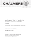
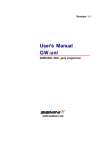
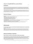
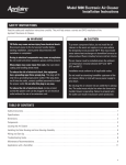
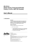
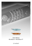
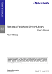
Freescale Semiconductor
Product Brief
Document Number: MC9S12XEPB
Rev. 7, 05/2008
This document contains
preview information on a new
product that may be in a design
phase or under development.
Freescale reserves the right to
change or discontinue this
product without notice.
MC9S12XE Family Product Brief
16-Bit Microcontroller Family with Enhanced System
Integrity Features
The new MC9S12XE Family of microcontrollers takes
the innovation of today’s MC9S12XD Family a step
further with the introduction of new features to deliver
enhanced system integrity and greater functionality.
These new features include a Memory Protection Unit
(MPU) and Error Correction Code (ECC) on the Flash
memory together with enhanced EEPROM functionality
(EEE), an enhanced XGATE, a Frequency Modulated
Phase Locked Loop (IPLL) and a faster ATD. The
E Family will extend the S12X product range up to 1MB
of Flash memory with increased I/O capability in the
208-pin version of the flagship MC9S12XEP100.
Targeted at automotive multiplexing and generic auto
body applications, S12XE Family will deliver 32-bit
performance with all the advantages and efficiencies of a
16-bit MCU. It will retain the low cost, power
consumption, EMC and code-size efficiency advantages
currently enjoyed by users of Freescale’s existing 16-bit
S12 and S12X MCU families. There is a high level of
compatibility between the S12XE and S12XD families.
© Freescale Semiconductor, Inc., 2008. All rights reserved.
Contents
1
2
3
4
Application Examples . . . . . . . . . . . . . . . . . . . . . . . . . . . . 2
1.1 Body Controller Application Example . . . . . . . . . . . 2
1.2 Gateway Application Example. . . . . . . . . . . . . . . . . 3
Features . . . . . . . . . . . . . . . . . . . . . . . . . . . . . . . . . . . . . . 4
2.1 Block Diagram . . . . . . . . . . . . . . . . . . . . . . . . . . . . . 4
2.2 Peripheral and Memory Options S12XE Family . . . 5
2.3 Critical Performance Parameters . . . . . . . . . . . . . . 6
2.4 Chip-Level Features . . . . . . . . . . . . . . . . . . . . . . . . 6
2.5 Module Features . . . . . . . . . . . . . . . . . . . . . . . . . . . 7
Developer Environment. . . . . . . . . . . . . . . . . . . . . . . . . . 12
Document Revision History. . . . . . . . . . . . . . . . . . . . . . . 14
Application Examples
Like members of other S12X families, the S12XE Family will run 16-bit wide accesses without wait states
for all peripherals and memories.
The S12XE Family features an enhanced version of the performance-boosting XGATE co-processor
which is programmable in “C” language and runs at twice the bus frequency of the S12X with an
instruction set optimized for data movement, logic and bit manipulation instructions and which can service
any peripheral module on the device. The new enhanced version has improved interrupt handling
capability and is fully compatible with existing XGATE module.
As with the S12XD Family, the S12XE Family features an enhanced MSCAN module which, when used
in conjunction with XGATE, delivers FULL CAN performance with virtually unlimited number of
mailboxes and retains backwards compatibility with the MSCAN module featured on existing S12
products.
The S12XE Family has full 16-bit data paths throughout. The non-multiplexed expanded bus interface
available on the 144-pin versions allows an easy interface to external memories. In addition to the I/O ports
available in each module, up to 25 further I/O ports are available with interrupt capability allowing
wake-up from STOP or WAIT mode. The S12XE Family is available in 208-Pin MAPBGA, 144-pin LQFP
(both with optional external bus), 112-pin LQFP or 80-Pin QFP options.
1
Application Examples
The following sections describe target applications of the MC9S12XE.
1.1
Body Controller Application Example
In this example, the MC9S12XE is implementing the features of a typical car body controller application.
The module interfaces with the main CAN buses distributed in the car using the on-chip MSCAN module
whereas the LIN bus communicates with functions local to the body controller. In both cases the
communication functions are managed by the XGATE independently of the CPU. The MC9S12XE
provides direct control of power drivers for lights and pumps and reading of sensors, using the on-chip
PWM and ATD modules. Finally, the SPI interface to the RF receiver provides the interface to the car
remote access system.
MC9S12XE Family Product Brief, Rev. 7
2
Freescale Semiconductor
Application Examples
RF Receiver
Smart Power
Smart
Power
Switches
Smart
Power
Switches
Smart
Power
Switches
(lighting…)
SPI
SPI
Digital Inputs (including Input
Capture signals)
LS CAN Body
CAN P/I
S12XE
CAN P/I
XGATE
CAN P/I
EEPROM
Switch panel
and digital
sensors
Digital Outputs (PWM or not)
HS CAN Powertrain
Analog Inputs
HS CAN Diagnostic
SCI
Direct loads
(power latch,
pumps, locking…)
Diagnostic
Battery monitoring,
and misc. sensors
SCI
Power seat
LIN P/I
Door modules
LIN P/I
LIN
Steering column
Rain sensor & sunroof control
LIN
Figure 1. Body Controller Application Example
1.2
Gateway Application Example
In this application, the MC9S12XE provides gateway functionality between its on-chip CAN and LIN
modules. Much of the low-level communications functionality is handled by the XGATE, which frees the
CPU to manage higher level communications and other direct connections to the module.
LS CAN Body
Digital Inputs
CAN P/I
HS CAN Telematics
S12XE
CAN P/I
Switch panel
Digital Outputs (PWM or not)
Direct loads
HS/LS CAN Chassis
CAN P/I
SCI
XGATE
HS CAN Powertrain
LIN
Door modules right side
LIN P/I
CAN P/I
EEPROM
HS CAN Diagnostic
SCI
SCI
Door modules left side
SCI
Wiping
Front lighting
LIN P/I
LIN P/I
Steering column
Switch panels
LIN
LIN P/I
CAN P/I
Power seats
LIN
LIN
Rain sensor & sunroof control
Figure 2. Gateway Application Example
MC9S12XE Family Product Brief, Rev. 7
Freescale Semiconductor
3
Features
2
Features
Features of the S12XE Family are described in this section.
2.1
Block Diagram
PLL with Frequency
Modulation option
Reset Generation
and Test Entry
EWAIT
PA[7:0]
PTA
ADDR[15:8]
PB[7:0]
PTB
ADDR[7:0]
PC[7:0]
PTC
ADDR[22:16]
DATA[15:8]
PD[7:0]
DATA[7:0]
PTF
CS0
CS1
CS2
CS3
SDA
SCL
RXD
TXD
PF0
PF1
PF2
PF3
PF4
PF5
PF6
PF7
8ch 16-bit Timer
Enhanced Multilevel
Interrupt Module
MPU
XIRQ
IRQ
RW/WE
LSTRB/LDS
ECLK
MODA/TAGLO/RE
MODB/TAGHI
XCLKS/ECLKX2
PTD
PK[7:0]
PTK
Memory Protection
8 regions
XGATE
PE0
PE1
PE2
PE3
PE4
PE5
PE6
PE7
PTE
TEST
PWM
PIT
Non-Multiplexed External Bus Interface
RESET
Clock Monitor
COP Watchdog
Periodic Interrupt
Async. Periodic Int.
IIC0
Inter IC Module
SCI3
Asynchronous Serial IF
PWM[7:0]
8-bit 8 channel
Pulse Width Modulator
RXD
SCI0
TXD
Asynchronous Serial IF
RXD
SCI1
TXD
Asynchronous Serial IF
SPI0
MISO
Synchronous Serial IF
CAN0
msCAN 2.0B
CAN1
msCAN 2.0B
CAN2
msCAN 2.0B
CAN3
msCAN 2.0B
SCI4
Asynchronous Serial IF
SCI5
Asynchronous Serial IF
SCI6
Asynchronous Serial IF
SCI7
Asynchronous Serial IF
SCI2
Asynchronous Serial IF
MOSI
SCK
SS
MISO
MOSI
SCK
SS
MISO
MOSI
SCK
SS
RXCAN
TXCAN
RXCAN
TXCAN
RXCAN
TXCAN
RXCAN
TXCAN
RXD
TXD
RXD
TXD
RXD
TXD
RXD
TXD
RXD
TXD
IIC1
Inter IC Module
CAN4
msCAN 2.0B
SDA
SCL
RXCAN
TXCAN
Synchronous Serial IF
SPI1
Synchronous Serial IF
SPI2
PTAD0
XTAL
Amplitude Controlled
Low Power Pierce or
Full drive Pierce
Oscillator
IOC[7:0]
PTAD1
EXTAL
16-bit 8 channel
Timer
X
BKGD
Debug Module
Single-wire Background 4 address breakpoints
Debug Module
2 data breakpoints
512 Byte Trace Buffer
PTT
CPU12X
PT[7:0]
PTR
IOC[7:0]
16-bit 8 channel
Enhanced Capture Timer
TIM
PR[7:0]
PP[7:0]
PTS
Voltage Regulator
PAD[31:16]
PTH (Wake-up Int)
8/10/12-bit 16-channel AN[15:0]
Analog-Digital Converter
ECT
PTM
2K … 4K bytes EEPROM
VDDR
VDD1
VDDF
VDDPLL
PAD[15:0]
PTL
8/10/12-bit 16-channel AN[15:0]
Analog-Digital Converter
ATD1
12K … 64K bytes RAM
PTJ (Wake-up Int.)
ATD0
128K … 1M bytes Flash
PTP (Int)
Figure 3 shows a top-level block diagram of the S12XE Family.
PS0
PS1
PS2
PS3
PS4
PS5
PS6
PS7
PH0
PH1
PH2
PH3
PH4
PH5
PH6
PH7
PM0
PM1
PM2
PM3
PM4
PM5
PM6
PM7
PL0
PL1
PL2
PL3
PL4
PL5
PL6
PL7
PJ0
PJ1
PJ2
PJ3
PJ4
PJ5
PJ6
PJ7
Figure 3. MC9S12XE Block Diagram
MC9S12XE Family Product Brief, Rev. 7
4
Freescale Semiconductor
Features
2.2
Peripheral and Memory Options S12XE Family
Table 1. Peripheral and Memory Options of S12XE Family Members
Device
Package
208 MAPBGA
9S12XEP100
9S12XEP768
9S12XEQ512
9S12XEQ384
9S12XET256
9S12XEG128
XGATE CAN1 SCI2 SPI3 IIC4
yes
5
8
3
2
ECT
TIM
PIT
A/D5 I/O6,7 Flash RAM
8ch
8ch
8ch
2/32
152
8
144LQFP
5
8
3
2
8ch
8ch
8ch
2/24
119
112LQFP
5
8
3
1
8ch
0
8ch
2/16
91
208 MAPBGA
5
8
3
2
8ch
8ch
8ch
2/32
152
144LQFP
5
8
3
2
8ch
8ch8
8ch
2/24
119
112LQFP
5
8
3
1
8ch
0
8ch
2/16
91
144LQFP
4
6
3
2
8ch
0
4ch
2/24
119
112LQFP
4
6
3
1
8ch
0
4ch
1/16
91
80QFP
4
2
3
1
8ch
0
4ch
1/8
59
144LQFP
4
6
3
2
8ch
0
4ch
2/24
119
112LQFP
4
6
3
1
8ch
0
4ch
2/16
91
80QFP
4
2
3
1
8ch
0
4ch
1/8
59
144LQFP
3
4
3
1
8ch
0
4ch
2/24
119
112LQFP
3
4
3
1
8ch
0
4ch
2/16
91
80QFP
3
2
3
1
8ch
0
4ch
1/8
59
2
2
2
1
8ch
0
2ch
2/16
91
2
2
2
1
8ch
0
2ch
1/8
59
112LQFP
80QFP
yes9
1M
EEPROM
(D-Flash)
64K
768K 48K
512K 32K
4K
(32K)
384K 24K
256K 16K
128K 12K
2K
(32K)
NOTES:
1 CAN Options:
Versions with 5 CAN modules will have CAN0, CAN1, CAN2, CAN3 and CAN4.
Versions with 4 CAN modules will have CAN0, CAN1, CAN2 and CAN4.
Versions with 3 CAN modules will have CAN0, CAN1 and CAN4.
Versions with 2 CAN modules will have CAN0 and CAN4.
Versions with 1 CAN module will have CAN0.
2 SCI Options:
Versions with 8 SCI modules will have SCI0, SCI1, SCI2, SCI3, SCI4, SCI5, SCI6 and SCI7.
Versions with 7 SCI modules will have SCI0, SCI1, SCI2, SCI3, SCI4, SCI5, and SCI6.
Versions with 6 SCI modules will have SCI0, SCI1, SCI2, SCI3, SCI4 and SCI5.
Versions with 5 SCI modules will have SCI0, SCI1, SCI2, SCI3 and SCI4.
Versions with 4 SCI modules will have SCI0, SCI1, SCI2 and SCI4.
Versions with 3 SCI modules will have SCI0, SCI1 and SCI2.
Versions with 2 SCI modules will have SCI0 and SCI1.
Versions with 1 SCI module will have SCI0.
3 SPI Options:
Versions with 3 SPI modules will have SPI0, SPI1 and SPI2.
Versions with 2 SPI modules will have SPI0 and SPI1.
Versions with 1 SPI modules will have SPI0.
4 IIC Options:
Versions with 2 IIC modules will have IIC0 and IIC1.
Versions with 1 IIC module will have IIC0.
5
A/D is the number of modules/total number of A/D channels.
6 I/O is the sum of ports capable to act as digital input or output. For details see the “Port Availability by Package Option” table
in the MCS12XE Data Sheet.
MC9S12XE Family Product Brief, Rev. 7
Freescale Semiconductor
5
Features
7
For additional flexibility, especially for the low pin count packages, several I/O functions can be routed under software control
to different pins. For details see the “Peripheral - Port Routing Options” in the MCS12XE Data Sheet.
8
Internal only, not bonded out
9
Can only execute code from RAM
2.3
Critical Performance Parameters
The following describes the critical operating parameters of the MCU.
2.3.1
•
•
•
2.3.2
•
•
•
•
2.4
Operating Conditions
Wide single supply voltage range 3.3V-5%/+10% to 5.0V+10% at full performance
— Separate supply for internal voltage regulator and I/O allow optimized EMC filtering
— 50MHz maximum CPU bus frequency
— 100MHz maximum XGATE bus frequency
Ambient temperature range –40°C to 125°C
Temperature Options:
— –40°C to 85°C
— –40°C to 105°C
— –40°C to 125°C
Package Options
208-pin MAPBGA - 17mm x 17mm body size (case no 1159A-01 issueB)
144-pin low-profile quad flat-pack (LQFP) - 20x20mm body size, 0.5mm pitch (case no 918-03)
112-pin low-profile quad flat-pack (LQFP) - 20x20mm, 0.65 pitch (case no 987)
80-pin quad flat-pack (QFP)- 14x14mm body, 0.65mm pitch (case no 841B)
Chip-Level Features
On-chip modules include the following features:
• Pin compatible family extends existing S12D Family
• 16-bit CPU12X
• Enables higher system integrity at the MCU level (MPU, ECC, Supervisor Mode)
• Enhanced SPI allows 8 or 16 bit data size
• ECC on flash
— 1-bit fault correction
— 2-bit fault detection
• Improved EMC performance
— Separate supply for internal voltage regulator and I/O allow optimized EMC filtering
• Enhanced current consumption
MC9S12XE Family Product Brief, Rev. 7
6
Freescale Semiconductor
Features
•
2.5
Extended API up to 5 sec
Module Features
The following sections provide more details of the modules implemented on the MC9S12XE.
2.5.1
•
•
•
•
2.5.2
•
•
•
•
•
2.5.3
•
•
•
•
•
•
•
•
2.5.4
•
•
•
•
16-Bit CPU12X
16-bit CPU12X
Compatible with MC9S12 instruction set with the exception of five fuzzy instructions (MEM,
WAV, WAVR, REV, REVW) which have been removed.
Enhanced indexed addressing
Access to large data segments independent of PPAGE
Enhanced Interrupt Module
Eight levels of nested interrupts
Flexible assignment of interrupt sources to each interrupt level.
External non-maskable high priority interrupt (XIRQ)
Internal, non-maskable high priority memory protection unit interrupt
Up to 24 pins on ports J, H and P configurable as rising or falling edge sensitive
XGATE
Programmable, high performance I/O coprocessor module with up to 100 MIPS RISC performance
Transfers data to or from all peripherals and RAM without CPU intervention or CPU wait states
Performs logical, shifts, arithmetic, and bit operations on data
Can interrupt the S12X CPU signalling transfer completion
Triggers from any hardware module as well as from the CPU possible
Two interrupt levels to service high priority tasks
Enables Full CAN capability when used in conjunction with MSCAN module
Full LIN master or slave capability when used in conjunction with the integrated LIN SCI modules
Memory Protection Unit (MPU)
8 address regions definable per active program task
Address range granularity as low as 8-bytes
Protection Attributes
— No write
— No execute
Non-maskable interrupt on access violation
MC9S12XE Family Product Brief, Rev. 7
Freescale Semiconductor
7
Features
2.5.5
•
•
•
•
•
•
2.5.6
•
•
•
•
•
•
System Integrity Support
Power-on reset (POR)
Illegal address detection with reset
Low-voltage detection with interrupt or reset
System can run in Supervisor or User state
— using a new bit in the condition code register
— peripheral space can only be accessed in user state if enabled by a descriptor
Computer Operating Properly (COP) watchdog
— Configurable as window COP for enhanced failure detection
— Can be initialized out of reset using option bits located in Flash
Clock monitor supervising the correct function of the oscillator
Memory Options
128K, 256K, 384K, 512K, 768K and 1M byte Flash
2K, 4K byte Emulated EEPROM
12K, 16K, 24K, 32K, 48K and 64K Byte RAM
Flash General Features
— 64 data bits plus 8 syndrome ECC (Error Correction Code) bits allow single bit failure
correction and double fault detection
— Erase sector size 1024 bytes
— Automated program and erase algorithm
— Security option to prevent unauthorized access
— Sense-amp margin level setting for reads
Data Flash General Features
— 32 Kbytes of D-Flash memory with 256-byte sectors for user access.
— Dedicated commands to access D-Flash memory over EEE operation
— Single bit fault correction and double fault detection within a word during read operations
— Automated program and erase algorithm with verify and generation of ECC parity bits
— Fast sector erase and word program operation
— Ability to program up to four words in a burst sequence
Emulated EEPROM General Features
— Automatic EEE file handling using internal Memory Controller
— Automatic transfer of valid EEE data from D-Flash memory to buffer RAM on reset
— Ability to monitor the number of outstanding EEE related buffer RAM words left to be
programmed into D-Flash memory
— Ability to disable EEE operation and allow priority access to the D-Flash memory
— Ability to cancel all pending EEE operations to allow priority access to the D-Flash memory
MC9S12XE Family Product Brief, Rev. 7
8
Freescale Semiconductor
Features
2.5.7
•
•
•
•
Oscillator (OSC_LCP)
Loop Control Pierce oscillator utilizing a 4MHz to 16MHz crystal
Good noise immunity
Full-swing Pierce option utilizing a 2MHz to 40MHz crystal
Transconductance sized for optimum start-up margin for typical crystals
2.5.8
•
•
Clock and Reset Generator (CRG)
Phase-locked-loop (IPLL) clock frequency multiplier
— Internally filtered. No external components required
— Configurable option to spread spectrum for reduced EMC radiation (frequency modulation)
Fast wake up from STOP in self clock mode for power saving and immediate program execution
2.5.9
•
•
Non-Multiplexed External Bus (208-pin and 144-pin packages only)
Up to four chip select outputs to select 16K, 1M, 2M and up to 4M byte address spaces
— Each chip select output can be configured to complete transaction on either the time-out of one
of the two wait state generators or the deassertion of EWAIT signal
Supports glue-less interface to popular asynchronous RAMs and Flash devices
2.5.10
•
•
•
•
•
•
•
•
Up to two independent ATD converters
8/10/12 bit resolution
Multiplexer for 16 analog input channels
3µs, 10-bit single conversion time
Left/right, signed/unsigned result data
External and internal conversion trigger capability
Internal oscillator for conversion in Stop modes
Wake-up from low power modes on analog comparison > or <= match
2.5.11
•
•
•
•
•
Analog-to-Digital Converter (ATD)
Enhanced Capture Timer (ECT)
8 x 16-bit channels for input capture or output compare
16-bit free-running counter with 8-bit precision prescaler
16-bit modulus down counter with 8-bit precision prescaler
Four 8-bit or two 16-bit pulse accumulators
Four channels have enhanced input capture capabilities:
— Delay counter for noise immunity
— 16-bit capture buffer
MC9S12XE Family Product Brief, Rev. 7
Freescale Semiconductor
9
Features
— 8-bit pulse accumulator buffer
2.5.12
•
•
•
8 x 16-bit channels for input capture or output compare
16-bit free-running counter with 8-bit precision prescaler
One 16-bit pulse accumulator
2.5.13
•
•
•
•
•
Pulse Width Modulator (PWM)
8 channel x 8-bit or 4 channel x 16-bit Pulse Width Modulator
Programmable period and duty cycle per channel
Center- or left-aligned outputs
Programmable clock select logic with a wide range of frequencies
Fast emergency shutdown input
2.5.17
•
•
Asynchronous Periodic Interrupt (API)
Available in all modes including Full Stop mode
Trimmable to +-10% accuracy
Time-out periods range from 0.2ms to ~13s with a 0.2ms resolution
2.5.16
•
•
•
•
•
Real Time Interrupt (RTI)
Real time interrupt for task scheduling purposes or cyclic wake-up
Can be active in Pseudo Stop mode for low power precision timing tasks
2.5.15
•
•
•
Periodic Interrupt Timer (PIT)
Up to 8 timers with independent time-out periods
Time-out periods selectable between 1 and 224 bus clock cycles
Time-out interrupt and peripheral triggers
2.5.14
•
•
Timer (TIM)
Multi-scalable Controller Area Networks (MSCAN)
Up to five MSCAN modules
CAN 2.0 A, B software compatible
— Standard and extended data frames
— 0 - 8 bytes data length
— Programmable bit rate up to 1 Mbps
Five receive buffers with FIFO storage scheme
Three transmit buffers with internal prioritization
MC9S12XE Family Product Brief, Rev. 7
10
Freescale Semiconductor
Features
•
•
•
•
•
•
•
Flexible identifier acceptance filter programmable as:
— 2 x 32-bit
— 4 x 16-bit
— 8 x 8-bit
Wake-up with integrated low pass filter option
Loop back for self test
Listen-only mode to monitor CAN bus
Bus-off recovery by software intervention or automatically
16-bit time stamp of transmitted/received messages
FULL-CAN capability when used in conjunction with XGATE
2.5.18
•
•
•
•
•
•
•
Up to three SPI modules
Configurable 8 or 16-bit data size
Full-duplex or single-wire bidirectional
Double-buffered transmit and receive
Master or Slave mode
MSB-first or LSB-first shifting
Serial clock phase and polarity options
2.5.19
•
•
•
•
•
•
•
•
•
Serial Communication Interfaces (SCI)
Up to eight SCI modules
Full-duplex or single wire operation
Standard mark/space non-return-to-zero (NRZ) format
Selectable IrDA 1.4 return-to-zero-inverted (RZI) format with programmable pulse widths
13-bit baud rate selection
Programmable character length
Programmable polarity for transmitter and receiver
Receive wake-up on active edge
Break detect and transmit collision detect supporting LIN
2.5.20
•
•
•
•
•
Serial Peripheral Interface (SPI)
Inter-IC Module (IIC)
Up to two IIC modules
Compatible with Inter-IC Bus standard
Multi-master operation
Software programmable for one of 256 different serial clock frequencies
Broadcast mode support
MC9S12XE Family Product Brief, Rev. 7
Freescale Semiconductor
11
Developer Environment
•
10-bit address support
2.5.21
•
Background debug module (BDM) with single-wire interface
— Non-intrusive memory access commands
— Supports in-circuit programming of on-chip non-volatile memory
— Supports security
2.5.22
•
•
•
3
On-Chip Voltage Regulator (VREG)
Two parallel, linear voltage regulators with bandgap reference
Low-voltage detect (LVD) with low-voltage interrupt (LVI)
Power-on reset (POR) circuit
3V and 5V range operation
Low-voltage reset (LVR)
2.5.24
•
•
•
Debugger (xDBG)
Four comparators A, B, C and D
— Each can monitor CPU or XGATE buses
— A and C compares 23-bit address bus and 16-bit data bus with mask register
— B and D compares 23-bit address bus only
— Three comparator modes: exact address match, inside address range or outside address range
64 x 64-bit circular trace buffer to capture change-of-flow addresses or address and data of every
access
Tag-type or force-type hardware breakpoint requests
2.5.23
•
•
•
•
•
Background Debug (BDM)
Input/Output
Up to 152 general-purpose input/output (I/O) pins and 2 input-only pins
Hysteresis and configurable pull up/pull down device on all input pins
Configurable drive strength on all output pins
Developer Environment
The S12XE Family of MCUs supports similar tools and third party developers as other Freescale S12X
products, offering a widespread, established network of tools and software vendors. Available support
includes:
S12X Evaluation Board
• Full standardized header ring for all pins (except Oscillator and PLL)
MC9S12XE Family Product Brief, Rev. 7
12
Freescale Semiconductor
Developer Environment
•
•
•
•
•
•
•
•
•
•
•
•
•
•
6 LIN Interfaces
2 RS232(2) Interfaces
3 CAN Interfaces
Power Supply Connector
Prototyping area
USB, BDM and USB2BDM interface
Daughter boards with 144, 112, and 80 pin devices
Canned Oscillator
Pierce Oscillator provision
Reverse polarity protection
Configuration jumpers (mode pins, clock source, vreg)
0 Ohm resistor going from test to ground
Ground points
Kit includes:
— USB cable
— CodeWarrior CD
— 9S12XDP512 Service Pack CD
— EVB9S12X Evaluation Board User Manual
— SofTec System Software CD
— Status: Available Now!
MC9S12 Code Warrior Development System -> S12X “Service Pack” contains:
• CodeWarrior for OSEK
• Sophisticated project manager
— Build system with optimizing C/C++ compiler
— Graphical, source-level debugger
— Fast, cycle-accurate simulator
— Code coverage and profile analysis
— Flash programmer
• Evaluation Kit for MC9S12DT256
— Evaluation board
— BDI interface
— Power supplies and cables
• Metrowerks OSEK Real-Time Operating System (demo)
• Documentation package
MC9S12XE Family Product Brief, Rev. 7
Freescale Semiconductor
13
Document Revision History
Table 2. Tools Suppliers
Name / Tool
IDE/Compiler
Debugger
Simulator
Emulator
BDM Conn.
Software
CodeWarrior
X
X
X
Cosmic Software
X
X
X
IAR Systems
X
X
X
Hardware
P&E
Microcomputer
Systems, Inc.
iSystem
X
X
X
X
Nohau
X
X
Lauterbach
X
X
X
X
Drivers
4
Vector
• LIN 1.3 Master Driver S12X. LIN 2.0 Master Driver S12X (including XGATE)
• CAN Driver S12X (including XGATE). This includes COM and NM for specific OEM
configuration
3Soft
• I/O (HIS) Drivers + LIN 2.0 Master and Slave Drivers ProOSEK for S12X
Volcano
• LIN Drivers For S12 available and compatible for S12X
Document Revision History
Table 3 shows the revision history of this document.
Table 3. Revision History
Revision
Location(s)
Substantive Change(s)
Rev. 1
on page 2
on page 3
on page 4
various
Added block diagrams and introductory text for application example.
Added block diagrams and introductory text for application example.
Added VREG block and 208MBGA to Figure 3.
Made a number of typographical and editorial changes.
Rev. 2
on page 4
on page 5
on page 7
Replaced high-level block diagram with detailed block diagram.
Added Table 1.
Added Table 2
Rev. 3
various
on page 5
on page 7
on page 7
Replaced future tense with present tense
Corrected corrupted footnote font in Table 1.
Added dataflash column to Table 2.
Changed CPU compatibility text following removal of fuzzy instructions
Rev. 4
on page 5
Merged device family option tables
Rev. 5
on page 6
Added package mechanical information
Rev. 6
on page 5
Changed D-Flash size for S12XEG128
Rev. 7
on page 5
Corrected SCI,IIC,PIT counts in derivative table
MC9S12XE Family Product Brief, Rev. 7
14
Freescale Semiconductor
Document Revision History
MC9S12XE Family Product Brief, Rev. 7
Freescale Semiconductor
15
THIS PAGE INTENTIONALLY BLANK
How to Reach Us:
Home Page:
www.freescale.com
E-mail:
[email protected]
USA/Europe or Locations Not Listed:
Freescale Semiconductor
Technical Information Center, CH370
1300 N. Alma School Road
Chandler, Arizona 85224
+1-800-521-6274 or +1-480-768-2130
[email protected]
Europe, Middle East, and Africa:
Freescale Halbleiter Deutschland GmbH
Technical Information Center
Schatzbogen 7
81829 Muenchen, Germany
+44 1296 380 456 (English)
+46 8 52200080 (English)
+49 89 92103 559 (German)
+33 1 69 35 48 48 (French)
[email protected]
Japan:
Freescale Semiconductor Japan Ltd.
Headquarters
ARCO Tower 15F
1-8-1, Shimo-Meguro, Meguro-ku,
Tokyo 153-0064
Japan
0120 191014 or +81 3 5437 9125
[email protected]
Asia/Pacific:
Freescale Semiconductor Hong Kong Ltd.
Technical Information Center
2 Dai King Street
Tai Po Industrial Estate
Tai Po, N.T., Hong Kong
+800 2666 8080
[email protected]
For Literature Requests Only:
Freescale Semiconductor Literature Distribution Center
P.O. Box 5405
Denver, Colorado 80217
1-800-441-2447 or 303-675-2140
Fax: 303-675-2150
[email protected]
Document Number: MC9S12XEPB
Rev. 7
05/2008
Information in this document is provided solely to enable system and software
implementers to use Freescale Semiconductor products. There are no express or
implied copyright licenses granted hereunder to design or fabricate any integrated
circuits or integrated circuits based on the information in this document.
Freescale Semiconductor reserves the right to make changes without further notice to
any products herein. Freescale Semiconductor makes no warranty, representation or
guarantee regarding the suitability of its products for any particular purpose, nor does
Freescale Semiconductor assume any liability arising out of the application or use of any
product or circuit, and specifically disclaims any and all liability, including without
limitation consequential or incidental damages. “Typical” parameters that may be
provided in Freescale Semiconductor data sheets and/or specifications can and do vary
in different applications and actual performance may vary over time. All operating
parameters, including “Typicals”, must be validated for each customer application by
customer’s technical experts. Freescale Semiconductor does not convey any license
under its patent rights nor the rights of others. Freescale Semiconductor products are
not designed, intended, or authorized for use as components in systems intended for
surgical implant into the body, or other applications intended to support or sustain life,
or for any other application in which the failure of the Freescale Semiconductor product
could create a situation where personal injury or death may occur. Should Buyer
purchase or use Freescale Semiconductor products for any such unintended or
unauthorized application, Buyer shall indemnify and hold Freescale Semiconductor and
its officers, employees, subsidiaries, affiliates, and distributors harmless against all
claims, costs, damages, and expenses, and reasonable attorney fees arising out of,
directly or indirectly, any claim of personal injury or death associated with such
unintended or unauthorized use, even if such claim alleges that Freescale
Semiconductor was negligent regarding the design or manufacture of the part.
Freescale™ and the Freescale logo are trademarks of Freescale Semiconductor, Inc.
All other product or service names are the property of their respective owners.
© Freescale Semiconductor, Inc. 2008. All rights reserved.