1
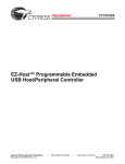
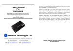
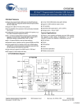
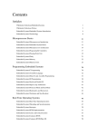
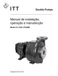
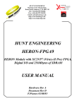
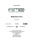
Implementation of a USB Slave to Slave File
Transfer Device Using Microcontrollers
Mark Alvin U. Chua Charles D. Jorge Ana Marian M. Pedro Brian Emmanuel G. Tam Gregory G. Cu
College of Computer Studies
De La Salle University – Manila
2401 Taft Ave., Manila
Abstract - The popularity of Universal Serial Bus (USB)
storage devices is an indication of the computer user's need
for a fast, large capacity and easily accessible system for data
storage.The disadvantage of USB storage devices is that being
a peripheral device, it needs a host,usually a Personal
Computer (PC) to initiate and mediate communications
between two USB storage devices. The USB based slave -toslave file transfer system seeks to create a bridge between two
slave devices for file transfer when a computer is unavailable.
The USB Slave -to-Slave File Transfer System (USS
FiTraDev) utilizes the Cypress CY76C7300 USB controller to
facilitate file transfers while a PIC18F458 microcontroller
handles the user interface. The user interface consists of four
scroll buttons, two multifunction control buttons and a 20x4
line LCD screen. The USS FitraDev system supports USB
flash drives that operate under the USB Mass Storage Class.
Copy functions include single file transfer, single folder
transfer and entire memory content transfer. The system
allows overwriting when a file of the same name is found in
the destination flash drive. An auto-rename function is also
available should the user choose to retain the file. The delete
function is enabled when the size of the file to be transferred
exceeds the available space on the destination flash drive. The
system has a file transfer accuracy of 100% for single files
and folders that are within the six-folder depth level with a
file transfer speed of 609.997Kbps. The use of five AA sized
alkaline batteries allows the transfer of up to 730MB of data
in a span of 6 hours and 34 minutes using a linear regulator
circuit.
I. INTRODUCTION
As the development of USB enabled peripherals increases, the
Universal Serial Bus (USB) has rapidly become a de facto standard
in communication with the Personal Computer (PC) and has lead to
new technologies for interfacing memory devices.
These
memory/storage devices connect to the USB ports and appear as
removable storage device in personal computers, the most popular
of which is the USB Flash Drive. The disadvantage of using USB
Flash Drives is that it requires a PC to initiate file transfers
between one another. [10]
As a solution to the USB Flash Drive disadvantage, the
research project aims to develop a device that allows file transfers
between two USB memory devices without the need for a Personal
Computer (PC). This paper discusses the current implementation
of all three modules as well as the testing process and partial
results from file transfer speed tests between USB Flash Drives of
different brands and capacities.
2 0
USB Flash Drive
(SOURCE)
L C D
X
S
c
4
R EE N
USB Flash Drive
(DESTINATION)
Figure 1. System Set-up
User
Button Press
Display
User input
command
User Interface
Controller
Path
Filename
Characters
(LFN )
File System
Controller
USB Flash
Drive (Source)
USB Flash Drive
Access Commands
Notification
NRZI and Serially
Encoded Packets
Screen
Content
FAT Table
System
Memory
Result
of Request
USB Controller
USB Flash
Drive
(Destination )
Figure 2. General Block Diagram
II. USB SLAVE TO SLAVE FILE TRANSFER DEVICE
The USB Slave to Slave File Transfer Device is a device that
facilitates file and folder/directory transfers from one flash drive to
another flash drive using the USB 1.1 interface without the need for
a Personal Computer (PC) to act as mediator. Figure 1 shows the
system setup while figure 2 shows the general block diagram of the
system.
The system allows the user to select files or folders/directories
for copying from a source flash drive to a user selectable directory
in the destination flash drive. The device also supports a copy all
function, which works the same way. Contents of the flash drives
are displayed in their 8.3 filename format thru a twenty character
by four lines - sized dot-matrix character liquid crystal display
Function Label
O P T I O N S
Vertical Scroll
}
A. User Interface Controller Module
This module is responsible for obtaining user input and
displaying user requested information thru an LCD. It consists of
three submodules namely the LCD Controller, Navigation and
Screen Display Formatter (as shown in figure 3).
Display
User
Button Press
Formatted Character
LCD
Representation Values
Controller
Submodule
Navigation
Submodule
User input
command
Screen
Display
Formatter
Submodule
Screen
Content
Path
Filename
Characters
(LFN)
File System
Controller
Figure 4. User Interface Controller Block Diagram
User input is received thru this module; however only two out
of the six buttons are interpreted and executed within the User
Interface Module. These buttons are the “Left” and “Right”
navigation buttons whose function are to scroll through the
displayed path or Long File Name (LFN) format of a file or
directory. The input from the “Up” and “Down” navigation
buttons and “Command Buttons 1 and 2” are converted to their
corresponding command codes and are forwarded to the File
System Controller module for execution. All information to be
displayed is received from the File System Controller module.
LCD Controller
The LCD Controller submodule is the hardware that interfaces
the LCD to the main hardware system. It is composed of a 20
character by 4 lines LCD and a microcontroller solely for
controlling the LCD and receiving user input.
Navigation
The Navigation submodule is the input handling hardware of
the system. This submodule includes six input buttons and
circuitry for filtering the input signals. The Navigation submodule
sends a corresponding signal for each button press to the
microcontroller that controls the LCD so that it could update the
screen and/or send commands to the File System Controller module
for processing (i.e. opening a folder and initiate a copy command).
Figure 5 shows the button layout of the Navigation submodule.
B A C K
}
(LCD). The system is also able to check for identical
file/folder/directory names and requests for a user confirmation to
either proceed and overwrite a file/folder/directory or not.
In addition, the system is able to check if there is sufficient
memory space for the file/folder/directory to be copied onto the
destination flash drive; if not, the system requests the user to
delete some files or folder/directories to free some memory in the
destination flash drive. The user may or may not opt to delete
anything.
Control Buttons
Horizontal Scroll
Figure 5. Button Layout
Screen Display Formatter
The Screen Display Formatter submodule is responsible for
arranging and ordering the contents of the LCD screen. It formats
the screen to display the appropriate option menus, folder
contents, path names, content type (folder or file).
The Screen Display Formatter submodule is the software part
of the User Interface module. It receives the names of the files and
folders to be displayed from the File System Controller module.
Figure 6 shows how the screen is formatted.
<Path of the Current Directory>
<First Content>
<Second Content>
<Mode>
<First Command> <Second Command>
Figure 6. Screen Format
B. File System Controller Module
The File System Controller is responsible for all file
management processes and FAT file system access for the system.
It mediates between the display/user interface and USB
communications module. A large percentage of the system’s
software is found in this module since it contains most of the
system’s core functions. Figure 7 shows the block diagram.
The major commands handled by the submodule include the
“up” and “down” navigation buttons and the different functions
attributed to “command button 1 and 2” (i.e., copy, delete,
browsing thru files/folders and the back command)
File Manager
The File Manager Submodule is responsible for all file
management functions/features that are available in the system.
These features include copying a file or folder, overwrite, rename,
delete, and browsing of the source and destination flash drive.
USB Host Controller
User Interface
Controller
Screen
Content Path
User input
command
Filename
Characters
(LFN)
File Manager
Submodule
Requested
Content
Notification
Content
Request
FAT 32/16/12
Controller
Submodule
USB Flash
Drive Access
Commands
FAT Table
System
Memory
Result of
Request
USB Controller
Figure 7. File System Controller Block Diagram\
FAT32/16/12 Controller
The FAT32/16/12 Controller mediates between the File
Manager submodule and the USB Controller Module. It is
responsible for abstracting the File System so that the File
Manager submodule could easily access the File System be it a
FAT 32, FAT16 or FAT12. A large portion of this submodule is
already implemented by the frameworks included with the Cypress
CY4640 Reference Design Kit. Error! Reference source not
found. However, some low-level functions required additional
SCSI commands to read some sectors of the FAT formatted
memory device.
The USB Host Controller submodule is the main hardware used
by both the USB Controller Module and the File System Controller
Module. The submodule physically interfaces with the USB flash
drives and is responsible for converting raw data and information to
their proper NRZI encoding as specified by the USB technical
specifications. Furthermore, the submodule is capable of encoding
or decoding the incoming NRZI data from the USB flash drives and
forwards it to their respective submodules for further processing.
The system uses the Cypress CY7C67300, a programmable
microcontroller and USB multi-role embedded host/peripheral
controller, which has its own Basic Input/Output System and
Framework program. Most of the software submodules make use
of the available framework where the functions are already
abstracted and simply need to be enabled and customized
depending on the application. [6]
Packet Handler
The Packet Handler submodule handles all packet generation
and interpretation. The submodule generates packets without error
checking bits, which will be used as either data, or command
packets depending on the command sent by the File System
Controller Module. Requests are interpreted and the error free
results and status notifications are sent as output.
File System Controller
USB Flash Drive
Access Commands
Start- up
Submodule
Request Device
Information
Packet Handler Submodule
Packets without
error checking bits
C. USB Controller Module
The USB Controller module is responsible for starting-up the
system, handling the packets, computation and checking of error
checking bits, packet encoding, conversion of packets from parallel
to serial and vice versa and NRZI decoding and encoding. This
module accepts the commands to either read or write onto a USB
flash drive as requested by the File System Controller Module.
Input from the USB flash drives is the result of an earlier request
for data. These requests include content information (i.e. file
names), actual content (i.e. files) or identification signals (i.e. the
connected USB device is checked if it falls under the Mass Storage
Class (MSC) or Human Interface Device (HID)). Block diagram is
shown in figure 8. [1] [2]
The module also governs the data that needs to be transmitted
to the USB Flash Drives, as well as process and send the results of
the transaction to the File System Controller Module. In addition,
the module also sends notifications to alert the user of the status of
the system or the operation (i.e. the status of a copy or delete
command).
Notification
Result of
Request
USB Device Information
Packets with error
checking bits removed
Error Bit Handling
Submodule
Serial Packets with Error
Checking Bits
USB Flash Drive
(Source)
[serial format]
NRZI and Serially
Encoded Packets
Serial
Handshake
[serial format ]
Received Serial
Raw data Packet
USB Host Controller
Submodule
USB Flash Drive
(Destination )
Figure 8. USB Controller Module Flowchart
Error Bit Handling
The Error Bit Handling Submodule is responsible for adding
error-checking bits to the data about to be sent. Furthermore, the
submodule also checks the received packets from the sender flash
drive for corrupted data. The submodule forwards an
acknowledgement (ACK) handshake in return if the received packet
does not contain any errors.
Start Up
The Start-up submodule handles the system start-up. It deals
with the detection of the USB devices attached to the system. The
submodule checks the USB ports for USB devices and their
properties. For the system to start-up properly, there must be (1)
two USB devices attached; (2) the USB devices must fall under the
Mass Storage Class (MSC) device class and (3) under the Solid
State device subclass; and (4) it must use the FAT 12/16/32 file
system. If any of the conditions fail other that the 2 USB device
requirement, an error would be raised.
III.
Performance Test
Table 3. Single File Transfer Test for USB Flash Drives with Different
Brands and Capacities
Destination Device: Average Speed
Source Device
Generic
16 MB
Generic 16 MB
195.208
Kbps
197.529
Kbps
PQI 256 MB
Threee tests are used to asses the performance of the system;
speed of the file transfers, accuracy of the copied files, and USB
Device recognition. Table 1 shows the brand, model and capacity
of the USB flash drives used while table 2 shows the test files
used.
A. Transfer Speed
Transcend 512
MB
Table 1. USB Flash Drives Used
Capacity
Manufacturer
Model
Year
Released
16 MB
Unknown
Unknown
~ 2002
256 MB
256 MB
512 MB
PQI
PQI
PQI
2006
2006
2006
512 MB
Transcend
Cool Drive U339S
Cool Drive U339S
Cool Drive U339S
JetFlash
TS512MJF120
2004
Table 2: Test Files
File Name
Standards.txt
Reflection Paper.doc
File Size in bytes
1,011
28,672
HP_App.doc
256,000
CIMG0478.JPG
999,424
KH2 Intro.mp3
CnC-Tiberium.mpg
4,912,691
13,287,428
B. Single File Copy Test
The file copy test involves six files with sizes ranging from
1,011 bytes to 13,287,428 bytes (12.6 MB). For each pair of flash
drives, all six files are copied and timed for three trials from which
the average time is taken. Table 2 shows files and its size being
transferred.
Table 4 lists the average speed at which the files were
transferred. The average speed was calculated by dividing the size
of the file to be transferred by the average time of three trials.
Transcend
512 MB
145.477
Kbps
143.519
Kbps
515.102
Kbps
-
Table 4. Single File Transfer Test Summary for USB Flash Drives with
Different Brands and Same capacities
Destination Device: Average Speed
Source Device
The results from the transfer speed test show that the speed of
the destination device is constant, for all pairs of USB flash disks.
The file transfer speed to the generic 16MB flash disk averages at
199.186Kbps, the 256 MB PQI at 558.191 Kbps, the 512MB PQI
at 171.376 Kbps and the 512MB Transcend at 144.548Kbps.
Overall, the 256MB PQI flash drive achieved the fastest speed of
609.977Kbps, paired with the generic 16MB flash drive as the
source for single file. Table 3 shows the result of this test.
PQI
256 MB
609.977
Kbps
Transcend 512 MB
PQI 512 MB
-
184.701 Kbps
142.862 Kbps
-
Transcend 512
MB
PQI 512 MB
C. Folder Copy Test
The Folder Copy Test involves five folders containing various
combinations of files and sub directories. The sizes of the folders
range from 53,900 bytes to 11,687,141 bytes. The folders have 17
to 91 files with folder depths ranging from 1 to 5. Table 7 shows
the test folder and its properties.
Table 7. Folder Copy Test - Test Folders
# of
# of
Folder Name
Depth
Files
Folders
LitFileDeep-6Lvl
5
17
7
SimpleManyLargeFiles
6
17
6
TotalMix -6lvl
6
92
16
MultiFolder-2
2
51
10
MultiASmall-Lvl1
1
38
0
MixLargeSmall-2Lvl
2
22
2
Size in bytes
7,121,893
4,447,312
11,610,853
5,965,149
123,532
3,508,969
Folder Descriptions:
1. LitFileDeep-6 Lvl - a mixture of small, medium and large files
in a partially complex folder structure.
2. SimpleManyLargeFiles - Single level folder structure having
medium sized files
3. TotalMix -6lvl - a mixture of small, medium and large files in a
complex folder structure in 6 levels
4. MultiFolder-2- 2 level structure with multiple folders inside
containing either no files, large files, small files, medium -sized
files or mix
5. MultiASmall-Lvl1 - 1 level folder that has several very small
files <2.5 KB.
6. MixLargeSmall-2Lvl- Mixture of large, small, and medium size
files in a 2 level folder structure
Large files are categorized as files over 1024 KB while Medium
files are between 20 KB and 1024 KB in size and Small files fall
below 20 KB. The recorded file sizes are based on the file’s actual
size and not on the amount of memory space they take up on disk.
The Folder depth is counted starting from the subdirectory of
the folder/directory concerned. Figure 9 illustrates how the folder
depth is determined.
VeryDeep
-
Root Level
1
-
First Level
-
Second Level
2
-
3
-
4
5
+
Message Digest Algorithm-5 (MD5). The MD5 results of the
original files are compared to the MD5 of the copied files to verify
the integrity of the written data. In total, each test file and folder is
transferred 33 times. The accuracy percentage is taken using the
ratio of the number of successfully transferred files and the total
number of files. Table 11 shows that files and folders transferred
are 100% accurate. It is also worthwhile to note that when the
folder transferred is beyond the six-level depth limit, the files and
folders beyond the said limit are not copied and would generally
lead to a low accuracy percentage. Another cause for inaccurate file
transfers would be that the prototype board is malfunctioning and
may need to be restarted or serviced.
Table 11. File Accuracy Test Results
Figure 9. Folder Depth Numbering
Filename
“VeryDeep” is the name of the folder to be transferred. Note
that the Root Level Folder, in this case the “VeryDeep”
folder/directory, is not counted as one level. The summary of the
test results are found in table 8, table 9 and table 10.
Destination Device: Average Speed
Source Device
Generic 16 MB
PQI 256 MB
Transcend
512 MB
Generic
16 MB
204.821
Kbps
207.615
Kbps
PQI
256 MB
571.171
Kbps
Transcend
512 MB
147.210 Kbps
-
143.874 Kbps
547.898
Kbps
-
Table 9. Folder Transfer Test Summary for USB Flash Drives with
Different Capacities
Source Device
PQI 256 MB
PQI 512 MB
Destination Device: Average Speed
PQI 256 MB
531.636 Kbps
533.972 Kbps
PQI 512 MB
182.263 Kbps
-
Accuracy
Single File Transfers
STANDA~1.TXT
REFLEC~1.DOC
Table 8. Folder Transfer Test Summary for USB Flash Drives with
Different Brands and Capacities
MD5
HP_APP.DOC
CIMG0478.JPG
KH2INT~1.MP3
CNC-TI~1.MPG
D9324F3FA083452F
04C5CAABABF26681
C0D07E2C71C2F9CE
1CB3DC3D782FD927
4856547D0F70C6D3
C91E2FF162F7834D
ADB0379FB28E36A6
4BD0D6C0BCA0681F
605195ED403842DD
A10CFF5A41D1B4B5
64A70C3DEDB53345
9C0B9D6954B6C3CB
100%
100%
100%
100%
100%
100%
Folder Transfers
LitFileDeep-6Lvl
100%
SimpleManyLargeFile
100%
s
TotalMix -6lvl
100%
MultiFolder-2
100%
MultiASmall-Lvl1
100%
MixLargeSmall-2Lvl
100%
Note: Folder transfer does not show any MD5 values because each
file has its own MD5 value.
IV. CONCLUSION
Table 10. Folder Transfer Test Summary for USB Flash Drives with
Different Brands and Same Capacities
Destination Device: Average Speed
Source Device
Transcend 512 MB
PQI 512 MB
Transcend 512
184.743 Kbps
MB
PQI 512 MB
144.348 Kbps
-
D. File Accuracy
A transfer transaction is considered successful if, for single file
copy, the file has been copied completely. For folder copy, all the
contents within the folder/directory concerned are copied
completely; this includes sub-folders and files within the folders to
be copied.
This test utilizes the files obtained from the Transfer Speed
test where they are compared to the original files using the
The design of the microcontroller system is based on the
simplified schematic of the CY4640 Mass Storage Reference
Design Kit (RDK), which uses the Cypress CY7C67300 USB
Host/Peripheral Controller. The external Serial EEPROM initially
holds the user’s program before it is loaded to the USB
Host/Peripheral chip. Since only 15K bytes of the USB
Host/Peripheral Controller’s internal memory is allocated for the
user’s program and data, it is not sufficient to hold the working
program of the prototype. An external SRAM was included in the
design to compensate for the lack of internal memory. The RS232
Transceiver is required by the LCD Module as well as for
debugging with the PC’s HyperTerminal. The USB
Host/Peripheral Controller requires a 12MHz clock source from
which an internal Phase Lock Loop (PLL) produces a 48MHz
internal clock. The same software used with the Cypress RDK is
able to run on the prototype board.
Test results verify that the maximum transfer speed of the
prototype is 609.977Kbps shown in table 3. Both speeds are taken
from the Single File transfer test, between the 16MB generic Flash
disk as source device and the 256MB PQI Flash disk as the
destination. It is observed however, that the speed of the
destination USB flash drive is an important factor for fast data
transfer; the source flash drive speed is irrelevant. Similar results
are seen with same capacity and same brand flash drive transfers.
The delete and overwrite functions proved successful during
software development and testing phase of the study, no recorded
tests are made for this function.
The system is able to operate successfully using batteries. The
most cost-effective approach is the use of five alkaline AA sized
batteries, which are able to transfer 730MB of data in a span of 6
hours and 34 minutes.
The user interface system is designed to allow the user to
browse and choose specific files or folders to transfer between the
source and destination devices. The screen consists of only the
important data to avoid cluttering the screen. The scrollable path
name is shown on the first line, followed by the first two contents
of the current directory. The last line contains the function labels
for the Left and Right Control buttons. The hardware interface
consists of the Up and Down Navigation buttons, which are used
to browse the contents of a directory, the Left and Right
Navigation buttons for scrolling through the path name and two
control buttons to execute functions displayed on the screen.
V. REFERENCES
[1] D. Anderson, D. Dzatko, “Universal Serial Bus System
Architecture,”. MindShare, Inc., 2001
[2] J. Axelson, “USB COMPLETE Second Edition,” Madison, WI:
Lakeview Research LLC, 2004
[3] ypress Semiconductor Co, “EZ-Host Mass Storage Reference
Design [online]” Available:
http://www.cypress.com/portal/server.pt?space=CommunityPage
&parentname=CommunityPage&in_hi_userid=2&control=SetCo
mmunity&CommunityID=209&PageID=418&r_folder=Referen
ce%20Designs&r_title=EZHost%20Mass%20Storage%20Refere
nce%20Design (June 24, 2005)
[4] Cypress Semiconductor Corporation, “OTG-BIOS User Manual
Version 1.2,” Cypress Semiconductor Corporation, California,
2003
[5] Cypress Semiconductor Corporation, “CY4640 Hardware User
Manual Version 1.1,” Cypress Semiconductor Corporation,
California, 2004
[6] Cypress Semiconductor Corporation, “ Framework User’s Guide
For the CY4640 Mass Storage Reference Design Kit,” Cypress
Semiconductor Corporation, California, 2004
[7] Cypress Semiconductor Corporation, “EZ-Host Programmable
Embedded USB Host/Peripheral Controller Specifications,”
Cypress Semiconductor Corporation, California, 2004
[8] Cypress Semiconductor Corporation, “Framework User’s Guide
For the CY4640 Reference Design Kit,” Cypress Semiconductor
Corporation, 2004
[9] Cypress Semiconductor Corporation, “CY4640 EZ-Host USB
MSC Reference Design 1.0,” Cypress Semiconductor
Corporation, California, California, September 17, 2004
[10] USBFlashDrive.org [site], “USB Flash Drives, USB Memory and
Portable Computer Hard Drive Information,” [online]
Available:
http://www.usbflashdrive.org/usbfd_overview.html, July 1, 2005