1
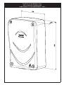
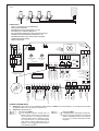
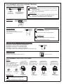
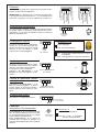
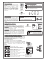
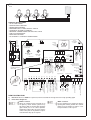
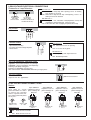
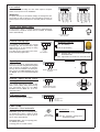
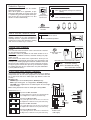
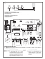
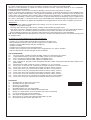
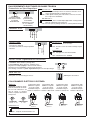
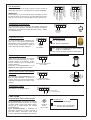
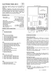
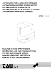
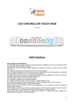
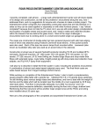
CENTRALINA ELETTRONICA DI COMANDO PER DIASSUASORI A DISTANZA
ELECTRONIC CONTROL UNIT FOR CYLINDRICAL TRAFFIC CONTROL POST
CENTRALE ÉLECTRONIQUE POUR BORNE ESCAMOTABLE AUTOMATIQUE CYLINDRIQUE
MANUALE D’INSTALLAZIONE E USO
INSTALLATION AND OPERATION MANUAL
MANUELPOUR LACONNEXION ET L’EMPLOI
I
GB
ART. ECD1
F
Il prodotto è conforme alla direttiva europea 2004/108/CE e successive.
Product is according to EC Directive 2004/108/CE and following norms.
Cod. S6I.ECD.100
RL. 00
2/2009
MISURE DI INGOMBRO ECD1
ECD1 OVERALLDIMENSIONS
DIMENSIONS D’ENCOMBREMENT ECD1
2
I
4
3
2
1
12
34
Comune
+
Alimentazione 230V
50Hz
Verde
Giallo
Rosso
GENERALITÀ
- FINO A 4 DISSUASORI A SCOMPARSA
- APERTURA PEDONALE
- PREDISPOSTO PER SEMAFORO A 3 LUCI
- AUTOMATICO O SEMIAUTOMATICO
- COLLEGAMENTI SEPARATI PER ELETTROVALVOLA
- SISTEMA DI SUPERVISIONE INTEGRITA' C.S.I.
- PREDISPOSIZIONE PER OROLOGIO ESTERNO
- FUNZIONE PASSO-PASSO
- UOMO PRESENTE
-
20VA 50/60Hz
USCITA 24V CC
Fusibile
Secondario
Trasformatore
F4= 2A
INNESTO PER SEMAFORO
A 3 LAMPADE MAX 100W
PER LAMPADA
TRASFORMATORE
-
-
+
52
53
+
T1
M4C
TEMPO DI PAUSA
1s - 180s
DIP-SWITCH
ON
Verde
1 2 3 4 5 6 7 8 91011 12
Cond. 20µF
M4
Cond. 20µF
M3
L12
L13
L14 L15
A
OFF
B
B
COMUNE
COMUNE
COMUNE
MOTORE M3
Dissuasore n°3
3
Fusibile Elettrovalvola,
Cicalino, Lampeggiatore e
Led F5=1A
M4
4
MOTORE M4
Dissuasore n°4
FINECORSA CHIUSURA M4
(Colonna alzata)
FINECORSA APERTURA M4
(Colonna abbassata)
FINECORSA CHIUSURA M3
(Colonna alzata)
FINECORSA APERTURA M3
(Colonna abbassata)
M3
Cond. 20µF M1
L2
L1
L3
L5
L4
L6
L7
L8
L9
L10
3
4
5
6
7
8
11 12 13 14 15
9 10
B
Cond. 20µF M2
A
B
16 17 18 19 20 21
N
NEUTRO
FASE
ALIMENTAZIONE QUADRO
230V ±10% 50Hz
MONOFASE
ALIMENTAZIONE
ELETTROVALVOLA
230V 50Hz
MOTORE M2
Dissuasore n°2
MOTORE M1
Dissuasore n°1
2
24 25
F
M2
M1
1
22 23
COMUNE
COMUNE
FINECORSA APERTURA M2
(Colonna abbassata)
FINECORSA CHIUSURA M2
(Colonna alzata)
COMUNE
FINECORSA CHIUSURA M1
(Colonna alzata)
FINECORSA APERTURA M1
(Colonna abbassata)
USCITA 24V 250mA per carico max:
- n°2 coppie di fotocellule
- n°1 Radio ricevente
SPIA 24V 3W max
BLOCCO
RADIO
APRE
CHIUDE
COMUNE
FOTOCELLULE O
SPIRA MAGNETICA
Morsetto per contatto
Passaggio pedonale Motore
Dissuasore M1
NUOVE FUNZIONI ECD1
2
Fusibile Motore M1
F1= 5A
Filtro antidisturbi
A
1
Fusibile Motore M2
F2= 5A
L11
Ingresso P
57 58
Fusibile
Motore M3
F7= 5A
31 32 33 34 35 36
26 27 28 29 30
(Optional: Schedina
Semaforo ad Innesto per
lampade a 230V)
A
Fusibile
Motore M4
F6= 5A
LAMPEGGIATORE
230V 100W max
Gialla
M3C M4A
T2
TEMPO DI LAVORO
1s - 22s
Rossa
M3A
LED DI SEGNALAZIONE
230V 100W MAX
Fusibile 1A
2)
51
COMUNE
63 64 65 66 60 61
1)
Fusibile Primario
Trasformatore
F3= 630mA
55 56
Attenzione: Ogni volta che viene ripristinata l’alimentazione all’ECD1, si devono attendere 10 secondi perchè la logica
del programmatore torni a funzionare regolarmente.
Diagnostica del finecorsa:
Dissuasori EBD2.
Con ponticello “STRIP” inserito (come in
figura) il ECD1 verifica con un tempo ciclico di 10 minuti se i finecorsa di chiusura
(colonna alzata) sono in posizione corretta; se ciò non fosse, vi è un avviamento dal
solo motore relativo al dissuasore non in
posizione, fino a raggiungimento della corretta posizione di salita.
Dissuasori EBD1.
È obbligatorio per i dissuasori col solo finecorsa di apertura posizionare il ponticello
“STRIP” in posizione libera, come in figura,
per avere un corretto funzionamento dell’impianto.
3
La centralina ECD1 di nuova generazione, è utilizzato per il dissuasore a scomparsa serie EBD. Alimentato a 230V monofase, risponde alle normative di sicurezza di Bassa Tensione BT 93/68/CE e Compatibilità Elettromagnetica EMC 93/68/CE, e
pertanto si consiglia l'installazione da parte di personale tecnico qualificato secondo le normative di sicurezza vigenti.
L'ECD1 si distingue per la capacità di monitorare eventuali guasti o malfunzionamenti dell'impianto (CSI)C.S.I.= Circuito di
Supervisione di Integrità, è una particolare funzionalità deli’ECD1 di poter monitorare l'intera scheda elettronica allo scopo di
rilevare qualsiasi guasto di un suo componente, o un malfunzionamento di un accessorio dell'impianto, tale per cui se l'automazione è provvista di Elettrovalvola di sblocco, consentel'abbassamento della colonna a scomparsa.
La Ditta costruttrice non si assume responsabilità circa l'uso improprio del programmatore; inoltre si riserva di apportare modifiche e aggiornamenti al presente libretto eal programmatore senza preavviso.
IMPORTANTE:
- Il programmatore deve essere installato in un luogo protetto e asciutto con la propria scatola di protezione
- Applicare un Interruttore Magneto
- Termico differenziale del tipo 0,03A ad alta sensibilità all'alimentazione del programmatore
- Scheda, Motore elettrico, Lampeggiante usare cavi con fili non inferiori a 1,5 mm2 fino a 50m di distanza; per Finecorsa e
accessori vari di comando e sicurezza utilizzarecavi con fili da 1mm2
- Per distanze superiori i 50 metri utilizzare fili di sezione idonea alla buona regola di installazione
N.B: Per applicazioni quali accensione luci, telecamere, ecc. utilizzare Relè Statici per non creare disturbi al microprocessore.
NEL CASO DI MANCATO FUNZIONAMENTO:
- Accertarsi che l'alimentazione al programmatore elettronico sia 230V ±10%
- Accertarsi che l'alimentazione al Motore Elettrico sia 230V ±10%
- Per distanze superiori ai 50 metri aumentare la sezione dei fili.
- Controllare la tensione di alimentazione 230V monofase
- Controllare i fusibili
- Controllare tutti i contatti chiusi del programmatore
- Controllare che non ci sia una caduta di tensione tra programmatore e motore elettrico
- Se presente l'Elettrovalvola controllare l'integrità di tutti i fusibili
LED DI DIAGNOSTICA
L1= Apre pedonale, normalmente SPENTO, si illumina a comando Apre Pedonale
L2= Fotocellule o Spira, normalmente ACCESO, si spegne con ostacolo presente
L3= Apre, normalmente SPENTO, si illumina ad impulso Apre
L4= Chiude, normalmente SPENTO, si illumina ad impulso Chiude
L5= Blocco, normalmente ACCESO, si spegne ad impulso di Blocco
L6= Radio, normalmente SPENTO, si illumina ad impulso Radio
L7= Normalmente ACCESO, tensione di rete e integrita' fusibili F1, F2, F3, F4
L8= Finecorsa Apertura M1, normalmente ACCESO, spento a colonna abbassata
L9= Finecorsa Chiusura M1, normalmente ACCESO, spento a colonna alzata
L10= Finecorsa Apertura M2, normalmente ACCESO, spento a colonna abbassata
L11= Finecorsa Chiusura M2, normalmente ACCESO, spento a colonna alzata
L12= Finecorsa Apertura M3, normalmente ACCESO, spento a colonna abbassata
L13= Finecorsa Chiusura M3, normalmente ACCESO, spento a colonna alzata
L14= Finecorsa Apertura M4, normalmente ACCESO, spento a colonna abbassata
L15= Finecorsa Chiusura M4, normalmente ACCESO, spento a colonna alzata
DIP-SWITCH
1=
ON Fotocellula o Spira ferma in apertura
2=
ON Radio non inverte in apertura
3=
ON Chiude in Automatico
4=
ON Prelampeggio Lampeggiatore Attivo
5=
ON Radio passo-passo con blocco intermedio
6=
ON Servizio un solo Dissuasore Pedonale Motore M1
7=
ON Servizio a Uomo Presente
8=
Gestione Semaforo (vedere riquadro delle funzioni)
9=
Gestione Semaforo (vedere riquadro delle funzioni)
10= ON Lampeggiatore spento in pausa
11= ON Richiude in pausa dopo passaggio fotocellule o spira
12= ON Tempo di lavoro massimo 90s. OFF= 18s
4
ON
1 2 3 4 5 6 7 8 9 10 11 12
OFF
COLLEGAMENTI ELETTRICI IN BASSA TENSIONE
Fotocellule o Spire Magnetiche:
DIP-SWITCH 1:
1
2
9 10
1
CONTATTO PER
FOTOCELLULE O
SPIRE MAGNETICHE
USCITA 24V (CARICO MAX:
N°2 COPPIE FOTOCELLULE
N°1 RADIO RICEVENTE)
DIP-SWITCH 11:
11
Pulsantiera:
3
4
5
ON: Fotocellula o spira ferma in apertura e inverte in chiusura a
ostacolo rimosso
OFF: Fotocellula o spira non ferma in apertura e inverte in chiusura in presenza di ostacolo
ON: Durante la pausa in Automatico (Dip-Switch 3=ON) al passaggio davanti le Fotocellule o Spira chiude dopo 5s
OFF: Non chiude al passaggio davanti le Fotocellule
6
NA NA
NC
CHIUDE
BLOCCO
APRE
COMUNE
Contatto Radio:
3
DIP-SWITCH 2:
7
ON: Non inverte in apertura
- Apre/Chiude (normale)
- Inversione di marcia ad ogni impulso
- Passo Passo
2
CONTATTO
RADIO
COMUNE
OFF: Inverte la marcia ad ogni impulso
DIP-SWITCH 5:
ON: Passo passo con blocco intermedio
5
OFF: Funzionamento normale
Spia 24V 3W di Segnalazione del movimento:
Spia Accesa = Colonna abbassata, passaggio libero
Spia Spenta = Colonna alzata, passaggio chiuso
Lampeggia a 0,5s (veloce) = movimento di salita
Lampeggia a 1s (normale) = movimento di discesa
Con orologio esterno: 2 brevi lampeggi seguito da una pausa più lunga
8
COMUNE
Uscita 24V CC:
3
+
-
Uscita per una eventuale utenza a 24V CC
200mA per accessori
55 56
COLLEGAMENTI ELETTRICI DI POTENZA
Motori:
Condensatore
Importante:
Durante il cablaggio è conve- aggiuntivo in mancanza di spunto per
niente collegare un solo
motore con i relativi finecorsa Motore M1 da 20µF
ed eseguire la "messa infase"
di un dissuasore per volta
A
T2
TEMPO DI PAUSA
1s - 180s
19 20 21
A
B
31 32 33
Condensatore
aggiuntivo in mancanza di spunto per
Motore M4 da 20µF
A
B
34 35 36
COMUNE
DIP-SWITCH 12:
+
B
Condensatore
aggiuntivo in mancanza di spunto per
Motore M3 da 20µF
COMUNE
T1
TEMPO DI LAVORO
1s - 22s
16 17 18
-
A
COMUNE
+
COMUNE
-
B
Condensatore
aggiuntivo in mancanza di spunto per
Motore M2 da 20µF
M1
M2
M3
M4
MOTORE M1
Dissuasore n°1
MOTORE M2
Dissuasore n°2
MOTORE M3
Dissuasore n°3
MOTORE M4
Dissuasore n°4
ON: Tempo di lavoro massimo 90s
12 OFF: Tempo di lavoro massimo 18s
5
Finecorsa:
11 12 13 14 15
26 27 28 29 30
FINECORSA CHIUSURA M4
(Colonna alzata)
COMUNE FINECORSA
FINECORSA APERTURA M4
(Colonna abbassata)
FINECORSA CHIUSURA M3
(Colonna alzata)
FINECORSA APERTURA M3
(Colonna abbassata)
FINECORSA CHIUSURA M2
(Colonna alzata)
COMUNE FINECORSA
FINECORSA APERTURA M2
(Colonna abbassata)
IMPORTANTE: Per Dissuasori con un solo finecorsa,ponticellare gli ingressi finecorsa di chiusura 12 e 15 non utilizzati con il
comune13 e gli ingressi 27 e 30 non utilizzati con il comune 28
FINECORSA CHIUSURA M1
(Colonna alzata)
FINECORSA APERTURA M1
(Colonna abbassata)
Non è necessario ponticellare gli ingressi dei finecorsa dei dissuasori non presenti nell'installazione
Alimentazione Elettrovalvola:
22
Con Elettrovalvola collegata, a mancata alimentazioneelettrica
del quadro, oppure in situazione dimalfunzionamento del programmatore, o in presenza di unfusibile bruciato, la colonna si
abbassa automaticamente.
25
DIP-SWITCH 4 e 10:
53
COMUNE
Si possono collegare sia il Lampeggiante
esterno sia i Led a luceintermittente funzionanti solo durante il movimento di salita
ediscesa. Il cavo da collegare è quello
segnato come cavolampeggiatore
52
24
ALIMENTAZIONE
ELETTROVALVOLA
230V 50Hz
Lampeggiante esterno:
51
23
ON:Prelampeggio
4
OFF: Senza prelampeggio
230V 100W MAX
ON: Lampeggiatore Disattivatodurante la pausa
in automatico
10 OFF: Lampeggia durante la pausain automatico
Led di segnalazione:
51
53
MARRONE
USCITA LED DI SEGNALAZIONE
230V 100W MAX
51
52
53
NERO
COMUNE
Cicalino di movimento (accessorio optional):
Collegando il filo Blu-Comune e il filo
Nero del cavo"lampeggiante" si attiva il
segnale sonoro di movimento disalita e
discesa all'interno della colonna a scomparsa
52
COMUNE
Uscita per Led a luce intermittente sempre
funzionanti duranteil movimento di salita e
discesa e nella sosta a colonna alzata.
Si spengono a colonna abbassata
Collegare il filo Blu-Comune e il filo
Marrone del cavo lampeggiatore del dissuasore.
USCITA PER CICALINO DI
MOVIMENTO 230V 100W MAX
Alimentazione quadro:
Alimentazione scheda programmatore.
22
23
24
FASE
N
NEUTRO
F
25
ALIMENTAZIONE QUADRO
230V ±10% 50Hz MONOFASE
FUNZIONI
Automatico / Semiautomatico:
Ciclo Automatico: ad un impulso di comando
apre, la colonna si abbassa, si ferma in Pausa
per il tempoimpostato sul trimmer T2, scaduto
il quale richiude automaticamente
Ciclo Semiautomatico: ad un impulso di
comando apre la colonna si abbassa. Per
Chiudere il passaggiobisogna dare l’impulso di
chiusura.
6
DIP-SWITCH 3:
-
+
T2
Tempo di Pausa
da 1 a 180s
ON= Chiude in Automatico
3
OFF=Non chiude in Automatico
Funzione Semiautomatico
Apertura Pedonale:
Comando separato dal comando di aperturanormale.
Quando tutti i dissuasori hanno lacolonna
alzata, ad impulso di ingresso P, con DipSwitch 6= On e 3=On, si abbassa la colonnadel dissuasore n°1 (Motore M1) per passaggiopedonale del tempo di pausa impostato
sulTrimmer T2, scaduto il quale richiudeautomaticamente.
Ingresso P
DIP-SWITCH
3 - 6 entrambi in ON
DIPON= Chiude in Automatico
OFF= Non chiude in Automatico Funzione
Semiautomatico
57 58
3
Morsetto
per contatto
Passaggio
pedonale
Motore
Dissuasore M1
-
ON= Apertura Pedonale Motore M1
6
OFF= Funzionamento normale
+
T2 Tempo di Pausa da
1 a 180s
Uomo Presente:
Si ottiene il comando di apertura e chiusura
"ad azione mantenuta" (senza autotenuta nei
Relè), quindi l'attiva presenza dell'operatore
durante tuttoil movimento dell'automazione
fino al rilascio del pulsante o della chiavedel
selettore
M1
M3
M2
M4
DIP-SWITCH 7
ON= Funzionamento a Uomo Presente
7
OFF= Funzionamento Normale
Orologio esterno
Orologio Esterno (Optional):
3
-
+
4
NA
COMUNE
APRE
T2 Tempo di Pausa da
1 a 180s
COMUNE
OROLOGIO:
La centralina elettronica ECD1 consente il collegamento di un
normale orologio orario per l'apertura-chiusuradel dissuasore.
Collegamento: collegare in parallelo il contatto NA dell'Orologio
con il morsetto n°4 APRE e n°3 COMUNE, attivando larichiusura
automatica con il Dip-Switch n°3=ON
Funzionamento: programmare l'orario di apertura sull'orologio,
all'ora impostata il dissuasore si abbassa rimanendo aperto(il
lampeggiante si spegne e la spia segnala con 2 brevi lampeggi
seguito da una pausa più lunga), e non accetterà piùnessun
comando (anche radio) sino allo scadere del tempo impostato
sull'orologio, allo scadere del quale dopo il tempodi pausa seguirà
la salita automatica.
DIP-SWITCH N°3 = ON Chiusura Automatica
3
ON= Chiude in Automatico
OFF= Non chiude in Automatico
Funzione Semiautomatico
OFF
8
OFF
9
ON
OFF
8
9
Dip-Switch 8=OFF e 9=ON
Si accende il Giallo per tempo 6s poi si accende il
Rosso edopo 5s si alza la colonna
ON
Dip-Switch 8=ON e 9=ON
Si accende il Giallo per tempo 10s poi si accende il
Rosso edopo 7s si alza la colonna
9
ON
8
9
Dip-Switch 8=ON e 9=OFF
Si accende il Giallo per tempo 2s poi si accende il
Rosso edopo 2s si alza la colonna
ON
OFF
8
Dip-Switch 8=OFF e 9=OFF
Si accende il Giallo per tempo 0s e dopo 0s si accende il Rosso esi alza la colonna immediatamente
Comune
Alimentazione
230V 50Hz
Giallo
DIP-SWITCH 8 e 9
Verde
Alimentazione della schedina è indipendente da quella della scheda
del programmatore:230V 50Hz con uscita di 100W a 230V per lampada.Funzionamento anche per Semaforo a 2 lampade Rosso e
Verde (Dip Switch 8=OFF e 9=OFF)
Logica di Funzionamento:
- Luce VERDE= Colonna abbassata, passaggio APERTO
- Luce ROSSA= Colonna in movimento o alzata, passaggio CHIUSO
- Luce GIALLA= interviene prima del passaggio da luce Verde a luce
Rossa
Nota: In funzionamento Pedonale il Semaforo rimane sempre
ROSSO.
Rosso
Schedina Semaforo ad Innesto (Optional):
ROSSO
63 64 65 66 60 61
GIALLO
Fusibile 1A
Rossa
VERDE
Gialla
Verde
(Optional: Schedina
Semaforo ad Innesto
perlampade a 230V)
7
GB
4
3
2
1
12
34
+
Power supply 230V
50Hz
Green
Yellow
Red
Common
GENERAL INSTRUCTIONS
- UP TO 4 BOLLARDS
- STEP-BY-STEP FUNCTION
- PEDESTRIAN OPENING
- PREPARED FOR 3 LAMPS TRAFFIC LIGHTS
- AUTOMATIC OR SEMI- AUTOMATIC
- SEPARATE CONNECTIONS FOR ELECTRIC VALVE
- TIME CLOCK EXTERNAL
- DEAD MAN CONTROL
- ISC SYSTEM i.e. INTEGRITY SUPERVISION
-
20VA 50/60Hz
Primary
fuse transformer
F3= 630mA
55 56
Secondary
fuse
transformer
F4= 2A
24V DC output
PLUG-IN CONNECTOR FOR 3LAMP TRAFFIC LIGHTS MAX
100W EACH LAMP
51
TRANSFORMER
-
-
+
+
T1
M4C
DWELL TIME
1s - 180s
DIP-SWITCH
ON
Green
1 2 3 4 5 6 7 8 91011 12
Cond. 20µF
M4
Cond. 20µF
M3
L12
L13
L14 L15
A
OFF
B
B
COMMON
COMMON
COMMON
4
MOTOR M4
Bollard n°4
MOTOR M3
Bollard n°3
LIMIT SWITCH CLOSE M4
(Bollard in up position)
LIMIT SWITCH OPEN M4
(Bollard in down position)
LIMIT SWITCH CLOSE M3
(Bollard in up position)
LIMIT SWITCH OPEN M3
(Bollard in down position)
3
Electric valve fuse,
Acoustic device, Flashing
light and Led F5=1A
M4
M3
L2
L3
L5
L4
L6
L7
L8
L9
L10
Anti-disturbance filter
A
1
2
3
4
5
6
7
8
B
A
B
16 17 18 19 20 21
11 12 13 14 15
9 10
Motor fuse M1
F1= 5A
L11
Input P
57 58
Motor fuse M2
F2= 5A
Capacitor 20µF M2
Capacitor 20µF M1
L1
Fusle Motor
M3 F7= 5A
31 32 33 34 35 36
26 27 28 29 30
(Optional: Plug-in PCB
for traffic light to suit
230 V lamp)
A
Fuse
Motore M4
F6= 5A
FLASHING LIGHT
230V 100W max
Yellow
M3C M4A
T2
MOTOR RUN TIME
1s - 22s
Red
M3A
SIGNAL LIGHT 230V
100W MAX
Fuse 1A
F
LIVE
NEUTRAL
POWER SUPPLY 230V ±10% 50Hz
SINGLE- PHASE
MOTOR M2
Bollard n°2
MOTOR M1
Bollard n°1
ELECTRIC VALVE POWER
SUPPLY
230V 50Hz
M2
2
24 25
N
COMMON
COMMON
LIMIT SWITCH OPEN M2
(Bollard in down position)
LIMIT SWITCH CLOSE M2
(Bollard in up position)
COMMON
LIMIT SWITCH CLOSE M1
(Bollard in up position)
LIMIT SWITCH OPEN M1 (Bollard
in down position)
OUTPUT 24V for max charge
n°2 pairs of photocells
n°1 Radio receiver
LED 24V 3W max
STOP
RADIO
CLOSE
OPEN
COMMON
PHOTOCELLS OR
MAGNETIC LOOP
Pedestrian opening
connection
Motor Bollard M1
M1
1
22 23
NEW FUNCTION ECD1
Note well: Whenever ECD1 is re-powered, wait 10 seconds for the logic to become fully operating again
Limit switch diagnostic:
EBD2 of ballards.
When the “STRIP” jumper inserted (as in
the picture), ECD1 checks cyclical every
10 minutes that the closing limit switches
(post raised) are in the correct position;
should any of them fail to be such, only the
motor of the post not in position is operated until this is fully up as required.
8
53
COMMON
63 64 65 66 60 61
1)
2)
52
EBD1 of ballards.
For the pasts that are fitted only with the
opening limit switch, position the “STRIP”
jumper as in the picture to achieve a correct performance of the system.
The electronic control panel ECD1, new generation, is designed to operate the EBD.
Power supply is 230V single-phase. Built in full compliance with BT 93/68/CE Low/High Voltage and EMC 93/68/CE ElectroMagnetic Compatibility Regulations. Fitting operations are recommended by a qualified technician in conformity tothe existing
safety standards.ECD1 is capable of monitoring damages or malfunctioning with the system (ISC).
I.S.C.= Integrity and Supervision Circuit, is a special function of ECD1 which can self control the electronic PCB and detect
any damages occurring with any componentsor accessories.
In this case, provided that the post is fitted with a release electric valve, lowering is allowed automatically.
The manufacturing company declines any responsability for incorrect handling and application; also, it reserves the right to
change or update the control panel any time
PLEASE NOTE:
- The control panel must be installed in a sheltered, dry place, inside the box provided with it.
- Fit the mains to the control panel with a 0.03A high performance circuit breaker.
- Use 1.5mm2 section wires for voltage supply, electric motor and flashing lamp. Maximum recommended distance 50m.
- Use 1mm2 section wires for limit switches, photocells, push-buttons/key- switch and accessories.
N.W: To fit extra accessories such as lights, CCTV etc. use only solid state relays to prevent damages to the microprocessor.
IN CASE OF FAILURE OF THE PANEL:
- Check the electronic PCB voltage supply is 230V
- Check the electric motor power supply is 230 V
- Check fuses
- Check photocells if contacts are normally closed
- Check all NC contacts
- Check that no voltage drop has occurred from the control board to the electric motor
- Check all the status indication leds- In case the electric valve is fitted, check integrity with all fuses.
LED STATUS INDICATION
L1=
Pedestrian opening, normally OFF, alight when a pedestrian open pulse is given
L2=
Photocells or loop, normally ALIGHT, if obstructed light goes off
L3=
Open, normally OFF, alight when an open pulse is given
L4=
Close, normally OFF, alight when a close pulse is given
L5=
Stop, normally ON, it goes off when a stop pulse is given
L6=
Radio, normally OFF, alight when a Radio pulse is given
L7=
Normally ON, mains voltage and fuse integrity F1, F2, F3, F4
L8=
Limit switch open M1, normally ON, it goes off when the post is in down position
L9=
Limit switch close M1, normally ON, it goes off when the post is in up position
L10= Limit switch open M2, normally ON, it goes off when the post is in down position
L11= Limit switch close M2, normally ON, it goes off when the post is in up position
L12= Limit switch open M3, normally ON, it goes off when the post is in down position
L13= Limit switch close M3, normally ON, it goes off when the post is in up position
L14= Limit switch open M4, normally ON, it goes off when the post is in down position
L15= Limit switch close M4, normally ON, it goes off when the post is in up position
DIP-SWITCH
1=
ON Photocells or loop stop while opening
2=
ON Radio no reversing while opening
3=
ON Automatic closing
4=
ON Pre flashing activated
5=
ON Radio step by step stop in between
6=
ON Pedestrian opening Motor M1only one post operating
7=
ON Dead man control
8=
Traffic lights (see functions)
9=
Traffic lights (see functions)
10= ON No lamp on during dwell time
11= ON Close on dwell time after passage through photocells or over the loop
12= ON Max working time 90s. OFF= 18s
ON
1 2 3 4 5 6 7 8 9 10 11 12
OFF
9
LOW VOLTAGE ELECTRICAL CONNECTIONS
Photocells or Loop Detectors:
DIP-SWITCH 1:
1
2
ON: Photocells or loop stop while opening,reverse on closing
once obstacle is removed
OFF: Photocells or loop do not stop whileopening, reverse on
closing in caseof an obstacle
9 10
1
CONTATTO PER
PHOTOCELLS
FOTOCELLULE
OR LOOPO
SPIRE MAGNETICHE
DETECTORS
24V24V
OUTPUT
USCITA
(CARICO MAX:
N°2 (MAX.
COPPIE LOAD:
FOTOCELLULE
N°1 RADIO
RICEVENTE)
2 PAIRS
PHOTOCELLS
DIP-SWITCH 11:
ON: During dwell time, Automatic mode(Dip-Switch 3=ON) after
engaging the photocellsor loop, it closes 5s later
OFF: It does not close after engaging the photocells or loop
1 RADIO RECEIVER)
11
Key switch:
3
4
5
6
NA NA
NC
BLOCCO
STOP
CHIUDE
CLOSE
APRE
OPEN
COMMON
C
OMUNE
Contatto Radio:
3
DIP-SWITCH 2:
7
ON: It does not reverse on opening
- Apre/Chiude (normale)
- Inversione di marcia ad ogni impulso
- Passo Passo
2
OFF: It reverses at any pulse
CONTACT
CRADIOONTATTO
RADIO
CCOMMON
OMUNE
DIP-SWITCH 5:
ON: Step by step with stop in between
5
OFF: Standard operation
24V 3W Movement Indication Light
Light ON = Post in down position, free passage
Light OFF = Post in up position, closed passage
Flashing 0,5s (fast)= rising post
Flashing 1s (normally)= lowering post
With external clock: 2 short flashes followed by a longer pause
3
COMUNE
COMMON
24V DC Output:
8
+
200mA
foraccessori
accessories
200mA per
Output for 24V D.C. applications
55 56
ELECTRICAL POWER CONNECTIONS
Motors:
Important:
when doing the electric
powerconnections it is better
to connect only onemotor
and its respective limit switches. Putthe posts into phase
one by one.
20µF additional
capacitor in case of
power shortage for
Motor M1
A
B
16 17 18
DIP-SWITCH 12:
ON:
Motor run time max 90s
12 OFF: Motor run time max 18s
10
19 20 21
M1
MOTOR
M1
MOTORE M1
Post
n°1 n°1
Dissuasore
A
B
31 32 33
M2
MOTOR
M2
MOTORE M2
Dissuasore
Post
n°2 n°2
20µF additional
capacitor in case of
power shortage for
Motor M4
A
B
34 35 36
COMMON
C
OMUNE
T2
DWELL
TIME
TEMPO
DI PAUSA
1s --180s
1s
180s
B
20µF additional
capacitor in case of
power shortage for
Motor M3
COMMON
COMUNE
T1
MOTOR
RUN
TEMPO
DI LAVORO
TIME
- 22s
1s 1s
- 22s
+
A
COMMON
COMUNE
-
+
COMMON
COMUNE
-
20µF additional
capacitor in case of
power shortage for
Motor M2
M3
MOTORE M3
MOTOR
M3
Dissuasore
Post
n°3 n°3
M4
MOTOR
M4
MOTORE M4
Post
n°4 n°4
Dissuasore
Limit switch:
11 12 13 14 15
26 27 28 29 30
COMMON LIMIT SWITCH
LIMIT SWITCH CLOSE M4
(Post in up position)
LIMIT SWITCH OPEN M4
(Post in down position)
25
LIMIT SWITCH CLOSE M3
(Post in up position)
LIMIT SWITCH CLOSE M2
(Post in up position)
24
LIMIT SWITCH OPEN M3
(Post in down position)
LIMIT SWITCH OPEN M2
(Post in down position)
COMMON LIMIT SWITCH
IMPORTANT:
For posts with only one limitswitch, bridge the closing limit switches inputs 12 and 15 (which are not used) with the common 13
and the inputs 27 and 30 (which are not used) with the common
28.
LIMIT SWITCH CLOSE M1
(Post in up position)
LIMIT SWITCH OPEN M1
(Post in down position)
There is no need to bridge the limit switch inputs of theposts
which are not present in the installation
Electric valve power supply:
22
In case of power failure, electronic programmer malfunctionning,
or a burnt fuse, should an electric valve be installed, the bollard
lowers automatically
23
ELECTRIC VALVE POWER
SUPPLY 230V 50Hz
External flashing light:
52
53
ON: Pre-flashing
COMMON
It is possible to connect both the external
Flashing light and theintermittent signal
lights which are on only during the rising
andlowering movement.
The cable for the connection is the onelabelled as flashing lights cable
DIP-SWITCH 4 and 10:
51
4
230V 100W MAX
OFF: No pre-flashing
ON: Flashing light out of serviceon Dwell Time.
Automatic mode
10 OFF: Light flashes on Dwell Time.Automatic mode
Signal lights:
51
BROWN
51
52
53
COMMON
BLACK
PCB power supply:
53
SIGNAL LIGHTS OUTPUT 230V
100W MAX
Acoustic signal during movement (optionalaccessory):
The acoustic signal device inside the bollard is active during rising and lowering.
The connection wires are the BlueCommon and the Black one of the flashing light cable
52
COMMON
Output for intermittent signal lights during
the movement both rising and lowering and
also on dwell in up position: the lightsare
off only when the bollard is in down position. Connect the Blue-Common wire and
the Brown wire of the bollard flashinglight
cable.
ACOUSTIC SIGNAL DEVICE
OUTPUT 230V 100W MAX
22
23
24
25
N
NEUTRAL
F
LIVE
Electric programmer power supply.
PCB POWER SUPPLY
230V ±10%
50Hz SINGLE PHASE
FUNCTIONS
Automatic / Semi-automatic:
Automatic cycle: after an opening pulse,
the bollard goes down, it stops for dwell
time pre-set in trimmerT2, after the pre-set
time it closes automatically
DIP-SWITCH 3
-
+
T2
Dwellditime
Tempo
Pausa
da 1
1 ato180s
from
180s
ON= Automatic closing
3
OFF=No automatic closing.Semiautomatic function
Semi-Automatic: after an opening pulse,
the bollard goes down.
A closing pulse is needed to close.
11
Pedestrian Opening:
This command is separate from the standardopening command.
When all the posts are in upposition, on pulsing input P Dip-Switch 6= On,and 3=On, post
n°1 (Motor M1) goes down forpedestrian opening, for the time pre-set inTrimmer T2, after
this time it closes automatically
Input PP
Ingresso
DIP-SWITCH
3 - 6 both on ON
DIPON= Automatic closing
OFF= No automatic closingsemi-automatic
closing
57 58
3
Pedestrian
opening contact
Post Motor M1
-
ON= Pedestrian opening Motor M1
6
OFF= Standard operation
+
T2 Dwell
time
from
Tempo di
Pausa
da
11 ato180s
180s
Hold on switched (Deadman) control:
Open and Close operations are achieved "by
holding a switch on (no relay self-holding is
involved) therefore a physical attendance is
required to keep the post opening or closing
until either the buttonor key is released.
M1
M3
M2
M4
DIP-SWITCH 7
ON= Deadman control
7
OFF= Standard operations
External clock
External Clock (Optional):
3
+
NA
DIP-SWITCH N°3=ON Automatic closing
3
ON= Automatic closing
OFF= No automatic closing.
Semi-automatic function
OFF
8
OFF
9
12
Comune
Common
Alimentazsupply
ione
Power
Hz
230V 5050Hz
230V
ON
Verde
9
ON
Dip-Switch 8=ON and 9=ON
The yellow light turns on for the time of 10s then the
Redlight turns on and after 7s the post starts rising
(Optional: Plug-in
PCB for 230V
traffic lights)
ON
9
YELLOW
GIALLO
Fusibile 1A
Dip-Switch 8=OFF and 9=ON
The yellow light turns on for the time of 6s then the
Red light turnson and after 5s the post starts rising
OFF
8
63 64 65 66 60 61
9
OFF
8
RED
ROSSO
Dip-Switch 8=ON and 9=OFF
The yellow light turns on for the time of 2s then the
Red lightturns on and after 2s the post starts rising
ON
8
Dip-Switch 8=OFF and 9=OFF
he yellow light turns on for the time of 0s and after 0s
the Redlight turns on and the post starts rising
Yellow
Giallo
Green
Verde
DIP-SWITCH 8 e 9
Red
Rosso
Plug-in traffic lights interface (Optional):
The interface power supply (230V 50Hz 100W output per lamp) is
independent from the one of the programmer.It can work also with
the 2 lamp Red and Green traffic lights (Dip Switch 8=OFF and
9=OFF)
Working logic:
- GREEN Light= Post in down position, OPEN passage
- RED Light= Moving post or in up position, CLOSED passage
- YELLOW Light= it lights before the switching from the Green light
to the Red light
Note: During Pedestrian mode the traffic light is always RED.
CCOMMON
OMUNE
T2 Dwell
time
from
Tempo di
Pausa
da
11 ato180s
180s
4
OPEN
APRE
-
COMUNE
COMMON
CLOCK:
The electronic control unit ECD1 can be connected to a clock for
the post opening and closing
Connection: connect in parallel the NO clock contact to the 4
OPEN and 3 COMMON terminals, automatic closing is by DipSwitch n°3=ON
How it works: Set the clock to the required times. On the pre-set
time the post is automatically opened (the post goes down) and
held open, (the flashing light goes off and the led flahes twice and
dwells) Any further pulsing (even by remote control) is not accepted by the system until the time pre-set by the clock has expired.
On expiring and after the pre-setdwell time the post automatically rises (automatic close).
Rossa
Gialla
Red
Yellow
Green
GREEN
VERDE
F
4
3
2
1
12
34
CARACTÉRISTIQUES GÉNÉRALES
- FONCTIONNEMENT DE 4 BORNES ESCAMOTABLES
- MAXIMUM AVEC OU SANS FINS DE COURSE
- FONCTION PAS PAS
- PREVU POUR L'INSTALLATION DU FEU DE SIGNALISATION A 3 AMPOULES
- OUVERTURE PASSAGE PIETONS
- AUTOMATIQUE OU SEMIAUTOMATIQUE
- LUMIERES DE SERVICE
- FONCTION HORLOGE
- HOMME MORT
Commun
Vert
Jaune
-
20VA 50/60Hz
Fusible Primaire
TransformateuF3=
630mA
55 56
Alimentation
230V 50Hz
Rouge
+
SORTIE 24V CC
Fusible
Secondaire
transformateur
F4= 2A
CONNECTEUR POUR FEU
DE SIGNALISATION A 3
AMPOULES MAX 100W
CHAQUE LAMPE
TRANSFORMATEUR
51
52
53
COMMUN
63 64 65 66 60 61
-
-
+
+
T1
M4C
TEMPS DE PAUSE
1s - 180s
DIP-SWITCH
ON
Vert
1 2 3 4 5 6 7 8 91011 12
Cond. 20µF
M4
Cond. 20µF
M3
L12
L13
L14 L15
A
OFF
B
B
COMMUN
COMMUN
COMMUN
MOTEUR M4
Borne n°4
3
Fusible Electrovalve,
Sonore, Clignotante Led
F5=1A
M4
4
MOTEUR M4
Borne n°4
FIN DE COURSE FERME M4
(Borne soulevée)
FIN DE COURSE OUVRE M4
(Borne baissée)
FIN DECOURSE FERME M3
(Borne soulevée)
FIN DE COURSE OUVRE M3
(Borne baissée)
M3
Cond. 20µF M1
L2
L1
L3
L5
L4
L6
L7
L8
L9
L10
2
3
4
5
6
7
8
11 12 13 14 15
9 10
Fusible Moteur M1
F1= 5A
Cond. 20µF M2
Filtre antibrouillage
A
1
Fusible Moteur M2
F2= 5A
L11
Entrée P
57 58
Fusible
Moteur M3
F5= 6,3A
31 32 33 34 35 36
26 27 28 29 30
(Optionnelle: Carte
enfichable pour feu de
signalisation pour lampes
à 230V)
A
Fusible
Moteur M4
F6= 6,3A
CLIGNOTANT 230V
100W max
Jaune
M3C M4A
T2
TEMPS DE TRAVAIL
1s - 22s
Rouge
M3A
LAMPE DE SIGNALISATION 230V
100W max
Fusible 1A
B
A
B
16 17 18 19 20 21
N
NEUTRE
ALIMENTATION 230V 50Hz
MONOPHASEE
MOTEUR M2
Borne n°2
MOTEUR M1
Borne n°1
ALIMENTATION
ELECTROVALVE
230V 50Hz
M2
2
24 25
F
PHASE
COMMUN
COMMUN
FIN DE COURSE OUVRE M2
(Borne baissée)
FIN DE COURSE FERME M2
(Borne soulevée)
COMMUN
FIN DE COURSE FERME M1
(Borne soulevée)
FIN DE COURSE OUVRE M2
(Borne baissée)
SORTIE 24V charge max
n°2 paires de cellules photo
n°1 Récepteur radio
LED 24V 3W max
ARRET
RADIO
OUVRE
FERME
COMMUN
CELLULES
PHOTOELECTRIQUES OU
SPIRE MAGNETIQUE
Borne pour contacte
Passage piétons Moteur
Borne M1
M1
1
22 23
NOUVELLES FONCTIONS ECD1
1)
2)
Attention: Toutes le fois qu’on va donner alimentation au ECD1, on doit attendre 10 secondes, afin que la logique du
programmateur.
Diagnostic des fins de course:
Bornes escamotables EBD2.
Avec une llaison “STRIP” introduite (comme
en figure), ECD1 vérifie avec un temps
cyclique de 10 minutes si les fins de course
de fermeture (borne levée) sont en position
correcte; si cela ne pouvait pas être, il y a le
démarrage seulement du moteur rélatif à la
borne escamotable pas en position, jusqu’à
la position correcte de montée.
Bornes escamotables EBD1.
Pour les bornes escamotables qui ont seulement le fin de course d’ouverture, c’est
obligatoire positionner la llaison “STRIP”
en position libre, comme dans la figure,
pour avoir un correct fonctionnement de
l’installation.
13
La centrale électronique ECD1 de nouvelle conception, est utilisé avec les bornes escamotables EDB.
Alimenté en 230V monophasé, il répond aux normes desécurité de Basse Tension BT 93/68/CE et de la Compatibilité
Electromagnetique EMC 93/68/CE.
L'installation doit être effectuée par un technicien spécialisé, suivant les normes desécurité en vigueur.
L'ECD1 se diversifie pour la capacité de surveiller d'eventuelles pannes ou défaut de fonctionnement de l'installation (CSI)
C.S.I.= Circuit de Supervision d'Integrité, estun particulier fonctionnalité de la centrale électronique ECD1 de pouvoir surveiller l'entière carte électronique pour remarquer tout les abîmes de son composante, ou un défautde fonctionnement d'un
accessoire de l'installation, tel pour lequel si l'automation est pourvue d'Electrovalve de déblocage, il permet l'abaissement
de la borne escamotable.Le constructeur décline toute responsabilité pour l'utilisation impropre du programmateur et il se
réserve le droit de modifier ou d' apporter des modificatons au programmateurou à cette notice à n'importe quel moment.
IMPORTANT:
- Le programmateur il doit être installé dans un lieu protégé et sec avec sa boîte de protection
- Appliquer un Interrupteur magneto
- Thermique différentiel du type 0,03A à haute sensibilité à l'alimentation du programmateur
- Carte, Moteur électrique, Clignotant employer des câbles avec des fils pas inférieurs à 1.5 mm2 jusqu'à 50m de distance
; pour Fin de course et accessoires divers de commande et sûreté utiliser des câbles avec des fils de 1mm2
- Pour des distances supérieures les 50 mètres utiliser des fils de section pour la bonne règle d'installation
N.B : Pour des applications quel allumage lumières, caméras, etc utiliser Relè Statiques pour ne créer pas de dérangements
au microprocesseur.
AU CAS OU LE PROGRAMMATEUR NE FONCTIONNE PAS:
- Contrôler que la tension d'alimentation soit 230V ±10%
- Contrôler que la tension d'alimentation du Moteur Electrique soit 230V ±10%
- Pour des distances supérieures aux 50 mètres augmenter les sections des fils.
- Contrôler la tension d'alimentation 230V des monophases
- Contrôler les fusibles
- Contrôler tous les contacts fermés du programmateur
- Contrôler qu'il n'y ait pas de chute de tension entre le programmateur et le moteur électrique
- Si présent l'Electrovalve contrôler l'integrité de tous les fusibles
LED DE DIAGNOSTIC
L1=
Ouverture piétons, normalement NON ALLUME, s'allume au commande Ouvre Piétons
L2=
Cellules photoélectriques, normalement ALLUME, s'éteint en presence d'obstacle
L3=
Ouvre, normalement NON ALLUME, s'allume à l'impulsion ouvre
L4=
Ferme, normalement NON ALLUME, s'allume à l'impulsion Ferme
L5=
Arrêt, normalement ALLUME, s'éteint à l'impulsion d'arrêtL6= Radio, normalement NON ALLUME, s'allume à l'impulsion Radio
L7=
Normalement ALLUME, tension de réseau et fusibles F1, F2, F3, F4 intactes
L8=
Fin de course en Ouverture M1, normalement ALLUME, non allumé si la borne est baissée
L9=
Fin de course Ferme M1, normalement ALLUME, non allumé si borne soulevée
L10= Fin de course Ouvre M2, normalement ALLUME, non allumé si borne baissée
L11= Fin de course Ferme M2, normalement ALLUME, non allumé si borne soulevée
L12= Fin de course Ouvre M3, normalement ALLUME, non allumé si borne baissée
L13= Fin de course Ferme M3, normalement ALLUME, non allumé si borne soulevée
L14= Fin de course Ouverture M4, normalement ALLUME, non allumé si borne baissée
L15= Fin de course Ferme M4, normalement ALLUME,non allumé si borne soulevée
DIP-SWITCH
1=
ON Photocellule ou spire arrête à l'ouverture
2=
ON Radio n'inverse pas à l'ouverture
3=
ON Ferme en Automatique
4=
ON Présignalisation active
5=
ON Radio pas-pas avec arrêt intermediaire
6=
ON Service d'une seule borne passage piétons Moteur M1
7=
ON Service Homme Mort8= Feux de circulation (voir carré des fonctions)
9=
Feux de circulation (voir carré des fonctions)
10= ON Lampe de signalisation non active en pause
11= ON Refermeture en pause après passage photocellules ou spire
12= ON Temps de travail maximum 90s. OFF= 18s
14
ON
1 2 3 4 5 6 7 8 9 10 11 12
OFF
RACCORDEMENTS ELECTIQUES EN BASSE TENSION
Photocellules ou Spire Magnetique:
DIP-SWITCH 1:
1
2
9 10
1
CONTATTOPOUR
PER
CONTACT
FOTOCELLULE O
PHOTOCELLULES
SPIRE MAGNETICHE
OU SPIRE
MAGNETIQUE
USCITA
24V (CARICO
SORTIE
24VMAX:
N°2 COPPIE FOTOCELLULE
(CHARGE
MAX:
N°1
RADIO RICEVENTE)
DIP-SWITCH 11:
N°2 PAIRES
PHOTOCELLULES
EL. N°1 RECEPTEUR RADIO)
Contacteur à clé:
4
3
ON: Cellule photoélectrique arrête en ouverture etinverse en fermeture quand l'obstacle n'estplus present
OFF: Cellule photo n'arrête pas en ouverture et inverse en fermeture en presence d'obstacle
11
5
ON: Pendant la pause en automatique(Dip-Switch 3=ON) quand le
faisceau estocculté ferme après 5s
OFF: Ne ferme pas au passage devant les cellules photoélectriques
6
NA NA
NC
COMMUN
CHIUDE
B
LOCCO
ARRET
OUVRE
APRE
FERME
C
OMUNE
Contact Radio:
3
2
CCONTACT
ONTATTO
RRADIO
ADIO
CCOMMUN
OMUNE
- Ouvre/Ferme (normal)
- Inversion de marche à chaque impulsion
- Pas-Pas
DIP-SWITCH 2:
ON: N'inverse pas en ouverture
7
5
OFF: Inverse le sens de marche àchaque impulsion
DIP-SWITCH 5:
ON: Pas-pas avec arrêt intermediaire
OFF: Fonctionnement standard
Led 24V 3W de Signalisation du mouvement:
8
COMUNE
Sortie 24V CC:
3
COMMUN
Led Allumé= Borne baissée, passage libre
Led non Allumé= Borne soulevée, passage fermé
Clignotement à 0,5s (rapide)= mouvement de montée
Clignotement à 1s (normal)= mouvement de descente
Avec horloge extérieur= 2 petits clignotements puis une arrêt plus longue
+
200mA
pour
accessoires
200mA per
accessori
Sortie pour un eventuel usage à 24V CC
55 56
COLLEGAMENTI ELETTRICI DI POTENZA
Condensateur 20µF
Condensateur 20µF
Moteurs:
Condensateur 20µF
additionnel à ajouter
additionnel à ajouter
additionnel à ajouter
Important: pendant le raccoren cas de courant
en cas de courant
en cas de courant
dement onconseille de raccorinsuffisant lorsqu'on
insuffisant lorsqu'on
insuffisant lorsqu'on
der un seul moteuravec ses
démarre le Moteur M1 démarre le Moteur M2 démarre le Moteur M3
fins de course et effectuer
la"mise en phase" d'une borne
chaque fois.
A
DIP-SWITCH 12:
M1
MOTEUR
M1
MOTORE M1
Dissuasore
Borne
n°1 n°1
A
B
31 32 33
M2
MOTORE M2
MOTEUR
M2
Dissuasore
Borne
n°2 n°2
A
B
34 35 36
COMMUN
COMUNE
T2
TEMPS
PAUSE
TEMPO DE
DI PAUSA
1s -- 180s
180s
B
COMMUN
COMUNE
T1
TEMPO
DI LAVORO
TEMPS
DE
1s - 22s
TRAVAIL
1s - 22s
+
A
19 20 21
COMMUN
COMUNE
-
+
COMMUN
COMUNE
-
B
16 17 18
Condensateur 20µF
additionnel à ajouter
en cas de courant
insuffisant lorsqu'on
démarre le Moteur M4
M3
MOTEUR
M3
MOTORE M3
Dissuasore
Borne
n°3 n°3
M4
MOTEUR
M4
MOTORE M4
Borne
n°4 n°4
Dissuasore
ON: Temps de travail maximum 90s
12 OFF: Temps de travail maximum 18s
15
Fin de course:
26 27 28 29 30
11 12 13 14 15
FIN DE COURSE FERME
M4 (Borne montée)
COMMUN FIN DE COURSE
FIN DE COURSE OUVRE
M4 (Borne baissée)
24
FIN DE COURE FERME
M3 (Borne montée)
23
FIN DE COURSE OUVRE
M3 (Borne baissée)
22
FIN DE COURSE FERME
M2 (Borne montée)
COMMUN FIN DE COURSE
FIN DE COURSE OUVRE
M2 (Borne baissée)
IMPORTANT:
Pour les Bornes, avec un seul fin de course,accoupler les entrés
des fins de course en fermeture 12 et 15 non utilisés avec lecommun 13 et les entrés 27 et 30 non utilisés avec le commun 28.
FIN DE COURE FERME
M1 (Borne montée)
FIN DE COURSE OUVRE
M1 (Borne baissée)
Il n'est pas nécessaire de mettre à pont les entrés des fins de
course des bornesqui ne sont pas présentes dans l'installation
Alimentation Electrovalve:
Avec Electrovalve reliée, à manquée alimentation électriquedu
cadre, ou bien en situation de défaut de fonctionnementdu programmateur, ou en présence d'un fusible brûlé, laborne s'abaisse automatiquement.
ALIMENTATION
ELECTROVALVE
230V 50Hz
Clignotant externe:
51
52
DIP-SWITCH 4 e 10:
53
ON: Presignalisation
COMMUN
On peut raccorder soit le Clignotant extérieur soit le Led àlumière intermittente
fonctionnant seulement pendant lemouvement de montée et descente. Le câble est
celui marquécomme câble clignoteur.
25
4
230V 100W MAX
OFF: Sans presignalisation
ON: Lampe de signalisation non active pendant
la pause en automatque
10 OFF: Clignote pendant la pauseen automatique
Feux de signalisation:
51
53
MARRON
SORTIE FEUX DE SIGNALISATION
230V 100W MAX
51
52
53
NOIR
COMMUN
Son de mouvement (accessoire
optional):
En raccordant le fil bleu-Commun et le fil
Noir du câble"clignotant" on active les
segnale sonore de mouvement demontée
et descente à l'intérieur de la borne escamotable.
52
COMMUN
Sortie pour Led à lumière intermittente
toujours fonctionnantpendant le mouvement de montée et la descente et dansl'arrête à colonne levée. Ils s'éteignent à
colonne abaissée.
Raccorder le fil bleu-Commun et le fil
Marron du câble clignoteur de la borne.
SORTIE POUR SON DE
MOUVEMENT 230V 100W MAX
Alimentation cadre:
Alimentation carte programmateur.
22
23
24
N
NEUTRE
PHASE
F
25
ALIMENTATION CADRE
230V ±10% 50Hz MONOPHASE'
FONCTIONS
Automatique/ Semi-automatique:
Cycle Automatique: à l'impulsion de commande d'ouverture la borne descend, elle s'arrête
en Pause pourle temps rentré dans le potentiomètre T2, le temps terminé elle remonte
automatiquement
Cycle Semiautomatique: à l'impulsion de
commande d'ouverture la borne descend et
puis Elle s'arrête enouverture. Pour qu'elle
remonte il faut donner l'impulsion de fermeture.
16
DIP-SWITCH 3
-
+
T2
Tempo
di Pausa
Temps
de
daPause
1 a 180s
de 5 à 128s
ON= Ferme en Automatique
3
OFF=Ne ferme pas en Automatique
Fonction Semi-automatique
Ouverture Piétons:
Commande séparé par le commande d'ouverturenormale.
Lorsque tous les bornes ont la colonneélevée,
à impulsion d'entrée P, avec dip-Switch 6= On
et 3=On, on abaisse la colonne de la borne
n°1 (Moteur M1) pour passage pour piétons
dutemps de pause établi sur le Trimmer T2,
expiréqui enferme automatiquement.
DIP-SWITCH
3 - 6 tous deux in ON
DIP-
Ingresso P
ON= Ferme en automatique
OFF= Ne ferme pas en Automatique
Fonction Semiautomatique
57 58
3
Contacte
Passage
ouverture
piétons
Moteur
Borne M1
-
ON= Ouverture Piétons Moteur M1
6
OFF= Fonctionnement standard
+
Tempsdi de
Pause
T2 Tempo
Pausa
da
1da
a 180s
1 a 180s
Homme Mort:
M1
M3
M2
M4
DIP-SWITCH 7
On obtient commande d'ouverture et de fermeture "à action maintenue"(sans autotenue
dans le Relè), donc l'active présence du opérateurpendant tout le mouvement de l'automation jusqu'au relâchement dubouton ou de la
clé du sélecteur.
ON= Fonctionnement homme mort
7
OFF= Functionnement Standard
Horloge externe
Horloge Externe (Optional):
-
+
4
NA
CCOMMUN
OMUNE
AOUVRE
PRE
T2 Temps
Tempo dide
Pausa
da
Pause
1 a 1180s
da
a 180s
COMMUN
COMUNE
HORLOGE :
La centrale électronique ECD1 permet le raccordement d'une
normale horloge horaire pour l'ouverture-fermeture de la borne.
Raccordement : relier en parallèle le contacte NA de l'Horloge
avec la borne n°4 OUVRE et n°3 COMMUN, en activant lafermeture automatique avec le dip-Switch n°3=ON
Fonctionnement : programmer l'horaire d'ouverture sur l'horloge,
à l'heur établie la borne s'abaisse en restant ouvert (le clignotant
s'éteint et la lampe signale avec 2 brefs clignotes suivi d'une
pause plus longue), et il n'acceptera plus aucune commande
(même radio) jusqu'au temps établi sur l'horloge a expiré.
Après le temps de pause il suivra la montée automatique.
3
DIP-SWITCH N°3=ON Fermeture Automatique
ON= Ferme en Automatique
3
OFF= Ne ferme pas en Automatique
Fonction Semi-automatique
OFF
8
OFF
9
ON
OFF
8
9
ON
OFF
8
9
ON
8
ON
9
Dip-Switch 8=OFF e 9=OFF
Le feu Jaune s'allume pendant le temps de 0s et
après 0s le feu Rouge s'allume et la borne monte
Dip-Switch 8=ON e 9=OFF
Le feu Jaune s'allume pendant le temps de 2s puis
le Feu Rouge s'allume et après 2s la borne monte
Dip-Switch 8=OFF e 9=ON
Le feu Jaune s'allume pendant le temps de 6s puis
le Feu Rouge s'allume et après 5s la borne monte
Comune
Commun
AAlimentation
limentazione
0Hz
2230V
30V 550Hz
Jaune
Giallo
DIP-SWITCH 8 et 9
Vert
Verde
Alimentation de la carte indépendant de celle du programmateur:
230V 50Hz 100W à 230V chaque ampoule.
Fonctionnant aussi avec un Feu de signalisation à 2 ampoules Rouge
et Vert (Dip Switch 8=OFF et 9=OFF)
Logique de Fonctionnement:
- Feu VERT= Borne baissée, passage OUVERT
- Feu ROUGE= Borne en mouvement ou complètement montée, passage FERME
- Feu JAUNE= s'allume juste avant le passage du feu Vert au feu
Rouge
Nota: lorsque le fonctionnement Piétons est actif le feu reste ROUGE.
Rouge
Rosso
Carte enfichable optionnelle pour feu de signalisation (Optional):
ROUGE
ROSSO
63 64 65 66 60 61
JAUNE
GIALLO
Fusible1A
1A
Fusibile
Rouge
Rossa
Jaune
Gialla
VERT
VERDE
Vert
Verde
(En option: Carte enfiDip-Switch 8=ON e 9=ON
Le feu Jaune s'allume pendant le temps de 10s puis chable pour feu de traffic
lampe à 230V)
le Feu Rouge s'allume et après 7s la borne monte
17
GB
I
-
-
-
-
-
-
-
-
-
-
-
-
AVVERTENZE PER L'INSTALLATORE
Leggere attentamente le avvertenze contenute nel
presente documento in quanto forniscono importanti indicazioni riguardanti la sicurezza di installazione, d'uso e di manutenzione.
Dopo aver tolto l'imballaggio assicurarsi dell'integrità dell'apparecchio. Gli elementi dell'imballaggio (sacchetti di plastica, polistirolo espanso, ecc.)
non devono essere lasciati alla portata dei bambini in quanto potenziali fonti di pericolo.
L'esecuzione dell'impianto deve essere rispondente alle norme CEI vigenti.
È necessario prevedere a monte dell'alimentazione un appropriato interruttore di tipo bipolare
facilmente accessibile con separazione tra i contatti di almeno 3mm.
Prima di collegare l'apparecchio accertarsi che i
dati di targa siano rispondenti a quelli della rete di
distribuzione.
Questo apparecchio dovrà essere destinato solo
all'uso per il quale è stato espressamente concepito, e cioè per sistemi di citofonia. Ogni altro
uso è da considerarsi improprio e quindi pericoloso. Il costruttore non può essere considerato
responsabile per eventuali danni derivanti da usi
impropri, erronei ed irragionevoli.
Prima di effettuare qualsiasi operazione di pulizia o di
manutenzione, disinserire l'apparecchio dalla rete di
alimentazione elettrica, spegnendo l'interruttore dell'impianto.
In caso di guasto e/o di cattivo funzionamento dell'apparecchio, togliere l'alimentazione mediante
l'interruttore e non manometterlo. Per l'eventuale
riparazione rivolgersi solamente ad un centro di
assistenza tecnica autorizzato dal costruttore. Il
mancato rispetto di quanto sopra può compromettere la sicurezza dell'apparecchio.
Non ostruire le aperture o fessure di ventilazione o
di smaltimento calore e non esporre l’apparecchio
a stillicidio o spruzzi d’acqua.
L'installatore deve assicurarsi che le informazioni
per l'utente siano presenti sugli apparecchi
derivati.
Tutti gli apparecchi costituenti l'impianto devono
essere destinati esclusivamente all'uso per cui sono
stati concepiti.
L’interruttore onnipolare deve essere facilmente
accessibile.
ATTENZIONE: per evitare di ferirsi, questo apparecchio deve essere assicurato alla parete secondo le
istruzioni di installazione.
Questo documento dovrà sempre rimanere allegato alla documentazione dell'impianto.
Direttiva 2002/96/CE (WEEE, RAEE).
Il simbolo del cestino barrato riportato sull’apparecchio indica che il prodotto, alla fine della propria vita
utile, dovendo essere trattato separatamente dai
rifiuti domestici, deve essere conferito in un centro di
raccolta differenziata per apparecchiature elettriche
ed elettroniche oppure riconsegnato al rivenditore al
momento dell’acquisto di una nuova apparecchiatura
equivalente.
L’utente è responsabile del conferimento dell’apparecchio a fine vita alle appropriate strutture di raccolta. L’adeguata raccolta differenziata per l’avvio successivo dell’apparecchio dismesso al riciclaggio, al
trattamento e allo smaltimento ambientalmente compatibile contribuisce ad evitare possibili effetti negativi sull’ambiente e sulla salute e favorisce il riciclo dei
materiali di cui è composto il prodotto. Per informazioni più dettagliate inerenti i sistemi di raccolta
disponibili, rivolgersi al servizio locale di smaltimento
rifiuti, o al negozio in cui è stato effettuato l’acquisto.
Rischi legati alle sostanze considerate pericolose
(WEEE).
Secondo la nuova Direttiva WEEE sostanze che da
tempo sono utilizzate comunemente su apparecchi
elettrici ed elettronici sono considerate sostanze pericolose per le persone e l’ambiente. L’adeguata raccolta differenziata per l’avvio successivo dell’apparecchio dismesso al riciclaggio, al trattamento e allo
smaltimento ambientalmente compatibile contribuisce ad evitare possibili effetti negativi sull’ambiente e
sulla salute e favorisce il riciclo dei materiali di cui è
composto il prodotto.
18
-
-
-
-
-
-
-
-
SAFETY INSTRUCTIONS FOR INSTALLERS
Carefully read the instructions on this leaflet: they
give important information on the safety, use and
maintenance of the installation.
After removing the packing, check the integrity of
the set. Packing components (plastic bags,
expanded polystyrene etc.) are dangerous for children. Installation must be carried out according to
national safety regulations.
It is convenient to fit close to the supply voltage
source a proper bipolar type switch with 3 mm
separation (minimum) between contacts.
Before connecting the set, ensure that the data on
the label correspond to those of the mains.
Use this set only for the purposes designed, i.e.for
electric door-opener systems. Any other use may
be dangerous. The manufacturer is not responsible for damage caused by improper, erroneous or
irrational use.
Before cleaning or maintenance, disconnect the
set.
In case of failure or faulty operation, disconnect
the set and do not open it.
For repairs apply only to the technical assistance
centre authorized by the manufacturer.
Safety may be compromised if these instructions
are disregarded.
Do not obstruct opening of ventilation or heat exit
slots and do not expose the set to dripping or
sprinkling of water.
Installers must ensure that manuals with the
above instructions are left on connected units after
installation, for users' information.
All items must only be used for the purposes
designed.
The ominipolar switch must be easily accessed.
WARNING: to avoid the possibility of hurting yourself, this unit must be fixed to the wall according to
the installation instructions.
This leaflet must always be enclosed with the
equipment.
F
-
-
-
-
-
-
-
-
-
-
CONSEILS POUR L'INSTALLATEUR
Lire attentivement les instructions contenues dans
ce document puisqu'elles fournissent d'importantes
indications concernant la sécurité pour l'installation,
l'emploi et la maintenance.
Après avoir enlevé l'emballage s'assurer de l'intégrité de l'appareil. Les éléments de l'emballage
(sachets en plastique, polystyrène, etc.) ne doivent
pas être laissés à la portée des enfants, car ils peuvent être dangereux. L'exécution de l'installation
doit être conforme aux normes nationales.
Il est nécessaire de prévoir près de la source d’alimentation un interrupteur approprié, type bipolaire,
avec une separation entre les contacts d’au moins
3mm.
Avant de connecter l'appareil s'assurer que les données reportées sur l'étiquette soient les mêmes que
celles du réseau de distribution.
Cet appareil devra être destiné uniquement à l'emploi
pour lequel il a été expressément conçu, c'est-à-dire
pour l'alimentation des systèmes de portiers électriques. Tout autre emploi doit être considéré impropre
et donc dangereux. Le constructeur ne peut pas être
considéré responsable pour d'éventuels dommages
résultant de l'emploi impropre, erroné et
déraisonnable.
Avant d'effectuer n'importe quelle opération de nettoyage ou de maintenance, débrancher l'appareil du
réseau d'alimentation électrique, en éteignant l'interrupteur de l'installation.
En cas de panne et/ou de mauvais fonctionnement
de l'appareil, enlever l'alimentation au moyen de
l'interrupteur et ne pas le modifier.
Pour une éventuelle réparation s'adresser uniquement à un centre d'assistance technique autorisé
par le constructeur. Si on ne respecte pas les
instructions mentionnées ci-dessus on peut compromettre la sécurité de l'appareil.
Ne pas obstruer les ouvertures et les fentes de ventilation ou de refroidissement et ne pas exposer
l’appareil à l’égout ou jet d’eau.
L'installateur doit s'assurer que les renseignements
pour l'usager soient présents dans les appareils
connectés.
Tous les appareils constituant l'installation doivent
être destinés exclusivement à l'emploi pour lequel
ils ont été conçus.
L’interrupteur omnipolaire doit être d’accès aisé.
ATTENTION: pour éviter de se blesser, cet appareil
doit être assuré au mur selon les instructions d’installation.
Ce document devra être toujours joint avec l'appareillage.
Directive 2002/96/EC (WEEE)
The crossed-out wheelie bin symbol marked on the
product indicates that at the end of its useful life, the
product must be handled separately from household
refuse and must therefore be assigned to a differentiated collection centre for electrical and electronic
equipment or returned to the dealer upon purchase
of a new, equivalent item of equipment.
-
The user is responsible for assigning the equipment,
at the end of its life, to the appropriate collection facilities.
Suitable differentiated collection, for the purpose of
subsequent recycling of decommissioned equipment
and environmentally compatible treatment and disposal, helps prevent potential negative effects on health
and the environment and promotes the recycling of
the materials of which the product is made. For
further details regarding the collection systems available, contact your local waste disposal service or the
shop from which the equipment was purchased.
Directive 2002/96/CE (WEEE, RAEE)
Le symbole de panier barré se trouvant sur l'appareil indique que le produit, à la fin de sa vie utile, doit être traité
séparément des autres déchets domestiques et remis à
un centre de collecte différencié pour appareils électriques et électroniques ou remis au revendeur au moment
de l'achat d'un nouvel appareil équivalent.
Risks connected to substances considered as
dangerous (WEEE).
According to the WEEE Directive, substances since
long usually used on electric and electronic appliances are considered dangerous for people and the
environment. The adequate differentiated collection
for the subsequent dispatch of the appliance for the
recycling, treatment and dismantling (compatible with
the environment) help to avoid possible negative
effects on the environment and health and promote
the recycling of material with which the product is
compound.
-
-
L’usager est responsable du traitement de l'appareil
en fin de vie et de sa remise aux structures de collecte appropriées. La collecte différenciée pour le démarrage successif de l’appareil remis au recyclage, au
traitement et à l'élimination écocompatibles contribue
à éviter les effets négatifs environnementaux et sur la
santé tout en favorisant le recyclage des matériaux
dont se compose le produit. Pour des informations
plus détaillées sur les systèmes de collecte disponibles, contacter le service local d'élimination des
déchets ou le magasin qui a vendu l'appareil.
Risques liés aux substances considérées dangéreuses (WEEE).
Selon la Directive WEEE, substances qui sont utilisées depuis long temps habituellement dans des
appareils électriques et électroniques sont considerées dangéreuses pour les personnes et l'environnement. La collecte sélective pour le transfert suivant
de l’équipement destiné au recyclage, au traitement et
a l’écoulement environnemental compatible contribue
à éviter possibles effets négatifs sur l’environnement
et sur la salue et favorise le recyclage des matériaux
dont le produit est composé.
®
Communicating in style
COSTRUZIONI ELETTRONICHE S.p.a.:
Via Pontarola, 14/A - 35011 Campodarsego (PD)
Tel. 049/9202511 r.a. - Fax 049/9202603
INTERNET
SERVICE
http://www.elvox.xom
E-mail: [email protected]
GARANZIA DI PRODOTTO ELVOX - CONDIZIONI GENERALI
1) La suddetta garanzia convenzionale lascia impregiudicati i diritti del consumatore derivanti dalla applicazione della
Direttiva Comunitaria 99/44/CE riguardo la garanzia legale ed è regolata dal D.L. n. 24 del 02.02.2002 pubblicato sulla
G.U. n. 57 del 08.05.2002.
2) La garanzia dei prodotti ELVOX è di 24 mesi dalla data di acquisto e comprende la riparazione con sostituzione gratuita
delle parti che presentano difetti o vizi di materiale.
La denuncia di vizio del prodotto deve essere comunicata entro 2 mesi dal rilevamento del vizio, quindi per un periodo
totale di copertura di 26 mesi.
3) La ELVOX Costruzioni Elettroniche S.p.A. presta la garanzia preso i Centri di Assistenza, per i prodotti presentati o inviati completi unitamente al certificato di garanzia compilato in tutte le sue parti con il documento fiscale comprovante la data
di acquisto.
La riparazione o la sostituzione dei pezzi durante il periodo di garanzia non comporta un prolungamento del termine di
scadenza della garanzia stessa.
4) Il certificato di garanzia non copre:
- apparecchi non funzionanti a causa di una non corretta riparazione effettuata da soggetti non qualificati;
- le parti che presentano normale usura;
- cattivo o diverso uso non conforme a quello indicato nel manuale di istruzione e negli schemi allegati alle apparecchiature;
- tutti i danni causati da calamità naturali, manomissioni, alimentazione non corretta;
- i vizi di funzionamento derivanti da una non corretta installazione non effettuata conformemente alla documentazione fornita dalla ELVOX S.p.A.
- i danni causati dal trasporto da parte di soggetti terzi non sotto la responsabilità della ELVOX S.p.A.
Assistenza tecnica post garanzia
Gli interventi fuori garanzia comprendono le spese relative ai ricambi, alla manodopera ed al diritto fisso di chiamata.
19
®
Communicating in style
CERTIFICATO DI GARANZIA AUTOMAZIONI
(Allegare al prodotto in caso di riparazione in garanzia)
ARTICOLO/MATRICOLA
COLLAUDATORE
INDIRIZZO DELL’UTILIZZATORE:
Cognome.................................................................................................
Nome...................................................................
Via............................................................ CAP........................................ CITTA’.................................................. PR..........
Tel............................................
TIMBRO DELL’INSTALLATORE
DATA DI INSTALLAZIONE
ELVOX COSTRUZIONI
ELETTRONICHE S.p.A.
35011 Campodarsego (PD) - ITALY
Via Pontarola, 14/A
Tel. 049/9202511 r.a. Phone international... 39/49/9202511
Telefax Italia 049/9202603
Telefax Export Dept... 39/49/9202601
UNI EN ISO 9001
ELVOX INTERNET SERVICE
E-mail: [email protected]
http://www.elvox.com
E-mail export dept:
[email protected]
FILIALE DI MILANO:
Via Conti Biglia, 2 20162 (MILANO)
Tel. 02/6473360-6473561
Fax 02/6473733
E-mail: [email protected]
FILIALE TOSCANA:
Via Lunga 4/R 50142 FIRENZE
Tel. 055/7322870 - Telefax. 055/7322670
E-mail: [email protected]
20