1
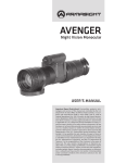
Avenger
Night Vision Monocular
Operation and
Maintenance Manual
Important Export Restrictions! Commodities, products, technologies and services of this manual are controlled by the U.S.
Department of State Office of Defense Trade Controls, in accordance with International Traffic in Arms (ITAR), Title 22, Code of
Federal Regulations Part 120-130 and/or by the Export Administration Regulations (EAR) of U.S. Department of Commerce. At any
time when a license or a written approval of the U.S. Government
is applicable to it, it is illegal and strictly forbidden to export, intend to export, transfer in any other manner whatsoever, sell any
hardware or technical data, provide any associated service to any
non-U.S. resident, beyond or within the United States territory,
until the valid license or written approval has been issued by the
Departments of the U.S. Government having jurisdiction. Additionally U.S. law prohibits the sale, transfer, or export of items to
certain restricted parties, destinations, and embargoed countries,
as identified on lists maintained by the U.S. Department of State,
the U.S. Department of Commerce, and the U.S. Department of
Treasury. It is the responsibility of the Customer to be aware of
these lists. The sale, transfer, transportation, or shipment outside of the U.S. of any product prohibited or restricted for export
without complying with U.S. export control laws and regulations,
including proper export licensing, documentation or authorization, is unlawful and may result in civil and/or criminal penalties
and/or constitute a federal crime. Diversion contrary to U.S. law
is strictly prohibited.
SAFETY SUMMARY
Before operating this product, carefully read and study this Operation and Maintenance Manual.
The Avenger is a precision electron-optical instrument, and requires careful handling. To avoid damage to the equipment or physical harm to the user when operating the Avenger, follow all WARNINGS,
CAUTIONS and NOTES.
Below you will find definitions of the following alerts that appear throughout this Manual:
WARNING — Identifies a clear danger to the person operating the equipment.
CAUTION – Identifies risk of damage to the equipment.
NOTE – Serves to highlight essential procedures, conditions, and statements, or convey important instructional data to the user.
WARNING:
This product contains natural rubber latex which may cause allergic reactions! The FDA
has reported an increase in the number of deaths that are associated with an apparent sensitivity to natural latex proteins. If you are allergic to latex, it is a good idea to learn which products
contain it and strictly avoid exposure to those products.
WARNINGS:
• Always make sure your firearm is unloaded before you place the scope on the firearm. Reconfirm that the chamber is empty if you stop the procedure then resume later. Safe handling rules
should be followed at all times.
• The light from the unit infrared (IR) illuminator is invisible to the unaided eye when used in
total darkness. However, the light can be detected by other Night Vision Devices (NVD).
• To reduce the risk of detection by another NVD, avoid prolonged activation of the IR illuminator.
• The IR light is more detectable by an NVD when used in smoke, fog and rain. Avoid prolonged activation of the unit IR illuminator in these conditions.
• This product contains natural rubber latex, which may cause allergic reactions.
• The intensifier’s phosphor screen contains toxic materials. Please note the following:
— If the intensifier tube breaks, be extremely careful to avoid inhaling the phosphor screen
material. DO NOT allow the material to come in contact with your mouth, eyes, or any open
wounds on the skin.
— If the phosphor screen material comes in contact with your skin, wash it off immediately with
soap and water.
— If you inhale or swallow any phosphor screen material, drink a lot of water, induce vomiting,
and seek medical attention as soon as possible.
The information provided in this manual is for familiarization purposes only. The contents may undergo further
changes with no commitment by Armasight© to notify customers of any updates.
Armasight© assumes no responsibility for any misprints or other errors that this manual may contain.
©2015 by Armasight. All rights reserved.
2
CAUTION:
• The Avenger is a precision electron-optical instrument, and must be handled carefully at all
times to prevent damage to the device and danger to the user.
• To protect the intensifier tube, do not remove the lens cap of the Avenger when the monocular is being operated in daylight conditions, or when the device is not in use.
• Use of the Avenger in brightly lit conditions may damage the unit’s intensifier tube.
• Bright light sources such as firelight, headlights, searchlights, etc. can damage the Avenger.
Avoid exposing the unit to these types of light sources.
• Before removing the lens cap, verify that the photoreceiver is open.
• DO NOT forget to open the photoreceiver after completing your mission.
• DO NOT attempt to force the controls past their stopping points, as this may cause damage
to the mechanisms.
• The unit may be badly damaged if the tripod on which it is mounted collapses or overturns.
Remove the unit from the tripod if it is not within your reach.
• Before replacing the intensifier tube, confirm that it is no longer covered by warranty.
• Thoroughly dry each component of the Avenger before placing them in the storage case.
NOTES:
• The equipment requires some ambient light (moonlight, starlight, etc.) to operate.
• Performance of the device in nighttime conditions depends on the level of ambient light in
the environment. Please remember the following:
— The level of ambient light is reduced by the presence of clouds, shade, or objects that block
natural light (trees, buildings, etc.).
— The equipment is less effective when operated in shadows and other darkened areas.
— The equipment is less effective when operated in rain, fog, sleet, snow, dust or smoke.
— The equipment will not “see” through dense smoke.
• At operating temperatures below -20°C (-4°F), the use of an alkaline battery is not recommended, as the battery life will be severely reduced. Under said conditions, lithium-iron disulfide 1.5V AA batteries or their equivalent should be used.
• The built-in IR illuminator is intended for increased illumination, as needed, when viewing at
a close distance of up to 20m.
• The Avenger is not a weapon sight. However, it can be used in conjunction with a collimator
dot sight or laser aiming device.
• For the purpose of returning defective components, retain all packaging materials.
3
LIST OF CONTENTS
TITLE
Safety Summary
List of Contents
List of Figures
List of Tables
How to Use This Manual
PAGE
2
4
5
6
6
1. INTRODUCTION
1.1 General Information
1.1.1 Type of Manual
1.1.2 Model Number and Equipment Name
1.1.3 Purpose of Equipment
1.1.4 Reporting Equipment Improvement Recommendations
1.2 Warranty Information and Registration
1.2.1 Warranty Information
1.2.2 Limitation of Liability
1.2.3 Product Warranty Registration
1.2.4 Obtaining Warranty Service
1.3 List of Abbreviations
7
7
7
7
7
7
8
8
8
8
9
10
2. DESCRIPTION AND DATA
2.1 System Description
2.2 Specifications
2.3 Standard Components
2.4 Optional Equipment
2.5 Key Features
11
11
13
14
15
16
3. OPERATING INSTRUCTIONS
3.1. Installation and Mounting
3.1.1 Battery Installation 3.1.2 Mounting the Avenger to a Weapon with a Quick Release Picatinny Mount Adapter
3.1.3 Mounting an Long-Range IR Illuminator to the Avenger
3.1.4 Mounting the Avenger to a Weapon with an AIM PRO Advanced Aiming Mount
3.1.5 Mounting a Camera/Camcorder to the Avenger
3.1.6 Universal Camera Adapter Application
3.2 Controls and Indicators
3.2.1 Controls and Indicators
3.3 Operating Procedures
3.3.1 Operating Procedures
3.3.2 IR Illuminator Operations
3.3.3 Operating Under Changing Light Conditions
3.3.4 Avenger Shut-Down
3.4 Storage 3.4.1 Preparation for Storage
17
17
17
18
18
19
19
19
20
20
21
21
22
22
23
23
23
4
4. PREVENTIVE MAINTENANCE AND TROUBLESHOOTING
4.1 Preventive Maintenance Checks and Services
4.1.1 Preventive Maintenance Checks and Services (PMCS)
4.2 Troubleshooting
4.2.1 Operator Troubleshooting
4.3 Identification of Operational Defects
4.3.1 Operational Defects
4.3.2 Cosmetic Blemishes
4.4 Maintenance
4.4.1 General
4.4.2 Cleaning Procedures
4.4.3 Battery Removal and Replacement
4.4.4 Goggle Kit Maintenance
4.5 Return Instructions
24
24
24
26
26
27
27
27
29
29
29
30
30
30
APPENDIX
A. Avenger List of Spare Parts
B. Product Warranty Registration Card
Alphabetical Index
31
31
33
35
LIST OF FigureS
FIGURE TITLE
2-1
2-2
3-1
3-2
3-3
3-4
3-5
3-6
3-7
3-8
3-9
4-1
4-2
4-3
4-4
4-5
A-1
Avenger Night Vision Monocular
Avenger Standard Components
Battery Installation
Mounting the Avenger to a Weapon with a Quick Release Picatinny Mount Adapter
Mounting an IR Illuminator to the Avenger
Mounting the Avenger to a Weapon with an AIM PRO
Mounting a Camera/Camcorder to the Avenger
Universal Camera Adapter Application
Avenger Controls
IR Illuminator Operations Photoreceiver Shading
Edge Glow
Emission Points and Bright Spots
Fixed-Pattern Noise
Chicken Wire
Avenger Spare Parts
PAGE
12
14
17
18
18
19
19
20
20
22
23 27
27
28
28
29
31
5
LIST OF Tables
TABLE
TITLE
2-1
2-2
2-3
2-4
2-5
2-6
2-7
3-1
4-1
4-2
A-1
Avenger System Description
Optical Data
Electrical Data
Mechanical Data
Environmental Data
Avenger Standard Components
Avenger Optional Equipment
Avenger Controls and Indicators
Preventive Maintenance Checks and Services
Operator Troubleshooting
Avenger List of Spare Parts
PAGE
12
13
13
13
13
14
15
21
24
26
31
HOW TO USE THIS MANUAL
USAGE
You must familiarize yourself with the entire manual before operating the equipment. Before performing any kind of maintenance on your device, read the section on maintenance in its entirety. Follow all
WARNINGS, CAUTIONS, and NOTES.
MANUAL OVERVIEW
This manual contains sections on Operating and Maintaining the Avenger Night Vision Monocular.
The list of Spare Parts can be found in Appendix A.
The Product Warranty Registration Card can be found in Appendix B.
6
1
INTRODUCTION
1.1 GENERAL INFORMATION
1.1.1 TYPE OF MANUAL
Operation and Maintenance (including a List of Spare Parts).
1.1.2 Model Number and Equipment Name
Avenger Night Vision Monocular.
1.1.3 PURPOSE of Equipment
To provide the operator with the ability to observe at night under moonlight and starlight conditions.
The Avenger can be used as a handheld or weapon-mounted device to allow short-range surveillance
and weapon firing. The Avenger can be mounted in front of a camcorder or camera for night photography, or it can be affixed to a rifle with a variety of different mounts.
1.1.4 Reporting Equipment Improvement Recommendations
Recommendations from the user for improvements to the device are encouraged.
Mail your comments to Armasight Inc., 815 Dubuque Avenue, South San Francisco, CA 94080, USA.
Or, send an email to [email protected].
7
1.2warranty INFORMATION and Registration
1.2.1 WARRANTY INFORMATION
This product is guaranteed to be free from manufacturing defects in material and workmanship under
normal use for a period of two (2) years from the date of purchase. In the event that a defect covered
by the below warranty occurs during the applicable period stated above, Armasight, at its discretion,
will either repair or replace the product; such action on the part of Armasight shall be the full extent of
Armasight’s liability, and the Customer’s sole and exclusive reparation. This warranty does not cover a
product if it has (a) been used in ways other than its normal and customary manner; (b) subjected to
misuse; (c) subjected to alterations, modifications or repairs by the Customer or by any party other than
Armasight without prior written consent of Armasight; (d) special order or “close-out” merchandise
or merchandise sold “as-is” by either Armasight or the Armasight dealer; or (e) merchandise that has
been discontinued by the manufacturer and either parts or replacement units are not available due to
reasons beyond the control of Armasight. Armasight shall not be responsible for any defects or damage that in Armasight’s view are a result from the mishandling, abuse, misuse, improper storage or
improper operation of the device, including use in conjunction with equipment that is electrically or
mechanically incompatible with, or of inferior quality to, the product, as well as failure to maintain the
environmental conditions specified by the manufacturer. CUSTOMER IS HEREBY NOTIFIED THAT OPERATION OF THE EQUIPMENT DURING DAYLIGHT HOURS OR UNDER ANY EXCESSIVE LIGHT CONDITIONS
MAY PERMANENTLY DAMAGE THE INTERNAL COMPONENTS OF THE UNIT AND SAID DAMAGE WILL
NOT BE COVERED UNDER THIS WARRANTY. This warranty is extended only to the original purchaser.
Any breach of this warranty shall be enforced unless the customer notifies Armasight at the address
noted below within the applicable warranty period.
The customer understands and agrees that except for the foregoing warranty, no other warranties
written or oral, statutory, expressed or implied, including any implied warranty of merchantability or
fitness for a particular purpose, shall apply to the product. All such implied warranties are hereby and
expressly disclaimed.
1.2.2 Limitation of Liability
Armasight will not be liable for any claims, actions, suits, proceedings, costs, expenses, damages or
liabilities arising out of the use of this product. Operation and use of the product are the sole responsibility of the Customer. Armasight’s sole undertaking is limited to providing the products and services
outlined herein in accordance with the terms and conditions of this Agreement. The provision of products sold and services performed by Armasight to the Customer shall not be interpreted, construed,
or regarded, either expressly or implied, as being for the benefit of or creating any obligation toward
any third party of legal entity outside Armasight and the Customer; Armasight’s obligations under this
Agreement extend solely to the Customer. Armasight’s liability hereunder for damages, regardless of
the form or action, shall not exceed the fees or other charges paid to Armasight by the customer or
customer’s dealer. Armasight shall not, in any event, be liable for special, indirect, incidental, or consequential damages, including, but not limited to, lost income, lost revenue, or lost profit, whether such
damages were foreseeable or not at the time of purchase, and whether or not such damages arise
out of a breach of warranty, a breach of agreement, negligence, strict liability or any other theory of
liability.
1.2.3 Product Warranty Registration
In order to validate the warranty on your product, Armasight must receive a completed Product Warranty Registration Card for each unit, or the Customer can complete a warranty registration on our
website, at www.armasight.com. Please complete the included form (Appendix B) and immediately
mail it to our Service Center:
Armasight Inc.
815 Dubuque Avenue
South San Francisco, CA 94080
United States of America
8
1.2.4 Obtaining Warranty Service
To obtain warranty service on your unit, the End-user (Customer) must notify the Armasight service
department via email. Send any requests to [email protected] to receive a Return Merchandise
Authorization number (RMA). When returning any device, please take in the product to your retailer, or
send the product, postage paid and with a copy of your sales receipt, to Armasight Corporation’s service center at the address listed above. All merchandise must be fully insured with the correct postage;
Armasight will not be responsible for improper postage or merchandise that becomes lost or damaged
during shipment. When sending product back, please clearly write the RMA# on the outside of the
shipping box. Please include a letter that indicates your RMA#, the Customer’s Name, a Return Address,
reason for the return, Contact information (valid telephone numbers and/or an e-mail address), and
proof of purchase that will help us to establish the valid start date of the warranty. Product merchandise returns that do not have an RMA# listed may be refused, or a significant delay in processing may
occur. Estimated Warranty service time is 10-20 business days. The End-user/ Customer is responsible
for postage to Armasight for warranty service. Armasight will cover return postage/ shipping after warranty repair to the End-user/ Customer only if the product is covered by the aforementioned warranty.
Armasight will return the product after warranty service by domestic UPS Ground service and/ or domestic mail. Should any other requested, required or international shipping methods be necessary, the
postage/ shipping fee will be the responsibility of the End-user/ Customer.
9
1.3 List of Abbreviations
C
CCW
Cont’d
CW
Dia
F
FOV
g
Gen
H
hr
IR
IT
L
LED
lx
m
mA
min
mm
mW
nm
No
NV
NVD
Para
PMCS
QRM
QTY
RMA#
s
seq
SR
VDC
V
W
10
Celsius (Centigrade)
counterclockwise
Continued
clockwise
diameter
Fahrenheit
Field of View
gram
Generation
Height
hour
infrared
Intensifier Tube
Length
Light Emitting Diode
lux
meter
milliampere
minute
millimeter
milliwatt
nanometer
Number
Night Vision
Night Vision Device
Paragraph
Preventive Maintenance Checks and Services
Quick Release Mount
Quantity
Return Merchandise Authorization number
second
sequence
Service Representative
Volts Direct Current
Volt
Width
2
DESCRIPTION AND DATA
2.1 System DESCRIPTION
The Avenger is a hand-held, or weapon-mounted night vision system that allows the user to operate
it while conducting short-range surveillance or while firing weapons in both moonlight and starlight
conditions.
The Avenger utilizes the principle of intensification of the residual light that is reflected from the surrounding objects. The optical system of the unit consists of an objective lens, an intensifier tube (IT),
and an eyepiece.
The Avenger automatic brightness adjustment system retains the same gain (image brightness), even
under unsteady light conditions.
The Avenger automatic protective system controls illumination through a photoreceiver. If the illumination level surpasses 100-300 lx for more than 10s, the unit will shut off automatically.
Automatic shut-off system automatically turns off the device when it is unused (controls are not
touched) for 60 minutes. The automatic shut-off function preserves battery life should the device be
inadvertently activated.
A built-in IR illuminator makes it possible to use the unit in low light or total darkness.
The Avenger is powered by a single AA or CR123A battery. Battery adapter is included.
The Avenger uses LED lights to indicate illumination level, low battery, and to show the user that the
IR illuminator is on.
The Armasight Avenger can be equipped with high-performance Gen 2+ and Gen 3 IITs including
Green Phosphor or White Phosphor IITs, which provide users with natural B&W night vision displays.
NOTE:
The equipment requires some light (moonlight, starlight, etc.) to operate. Performance of the
device depends upon the level of ambient light in the environment. Please remember the following:
— The level of ambient light in the environment is reduced by the presence of clouds, shade,
or objects that block natural light (trees, buildings, etc.
— The equipment is less effective when operated in shadows and other darkened areas.
— The equipment is less effective when operated in rain, fog, sleet, snow, or smoke.
— Under starlight conditions, particularly in low-contrast environments such as snow-covered territory, sandy deserts, large bodies of water or grassy hills, the visibility may degrade,
thereby disguising or masking changes in terrain.
— The equipment will not “see” through dense smoke.
11
11
10
9
8
6
7
5
12
4
3
2
13
1
14
Figure 2-1. Avenger night vision monocular
Table 2-1. Avenger System Description
Item
12
Description
Item
Description
1
Body
8
Photo Receiver
2
Rail
9
Pivotal Focusing Lens
3
Eyepiece Ring
10
IR Illuminator
4
Eyepiece
11
Turn-pull Function Switch
5
Eye-cup
12
Focus Ring
6
Battery Cap
13
Lens
7
Battery Compartment
14
Lens Cap
2.2 Specifications
Table 2-2. Optical Data
ITEM
DATA
Magnification:
3X
Lens:
— Focal Length
— Lens F/number
80 mm
1:1.65
Focus Range:
5 m to infinity
FOV:
12.6°
Exit Pupil Diameter
10 mm
Eye Relief
21.5 mm
Eyepiece Diopter Adjustment
-5 to +5 diopters
Built-in IR Illuminator:
— Power
— Illumination Range
— Illumination Wavelength
50 mW
up to 20 m
850 nm
Table 2-3. Electrical Data
ITEM
DATA
Battery
One AA (1.5 V) or one CR123A (3 V) *
Continuous Operation** at 20 oC (68 oF):
- AA Alkaline Battery
- CR123A Lithium Battery
40
60
* Any AA or CR123 type rechargeable batteries with voltage from 1.2V to 3.7V can be used
** With IR illuminator off.
Table 2-4. Mechanical Data
ITEM
DATA
Overall Dimensions
212 x 58 x 84 mm / 8.3 x 2.2 x 3.3 in
Weight (w/o battery)
670 g / 1.5 lbs
Table 2-5. Environmental Data
ITEM
DATA
Operating Temperature
-40 to +50 °C
Storage Temperature
-50 to +70 °C
Humidity
95%, 25°C to 40°C for 48 hr
Illumination Required
Natural night illumination
(overcast starlight to moonlight)
Environmental Rating
Water and fog-resistant
13
2.3 STANDARD COMPONENTS
The standard components of the Avenger are shown in Figure 2-2 and listed in Table 2-6.
The ITEM NO. column indicates the number used to identify items in Figure 2-2.
3
1
4
5
2
6
7
Figure 2-2. Avenger standard components
Table 2-6. Avenger standard components
ITEM no.
DESCRIPTION
QUANTITY
1
Night Vision Monocular
1
2
Lens Cap
1
3
Eye-cup
1
4
Battery Adapter
1
5
Battery
1
6
Operation and Maintenance Manual
1
7
Carrying Case
1
1) Armasight Avenger Night Vision Monocular
Monocular night vision device with unity magnification.
2) Lens Cap
A cap used to protect the lens and to be used when testing the unit in daylight.
3) Eye-cup
A rubber cup used to protect the eyepiece as well as provide comfort for the operator.
4) Battery Adapter
Allows of use of a single CR123 or AA batteries.
5) Battery
A single battery used to power the unit.
6) Operation and Maintenance Manual
Provides safety information, equipment description, mounting procedures, operating instructions,
and preventive maintenance checks and service (including a List of Spare Parts).
7) Carrying Case
A protective case used for storing and carrying of the Avenger and its accessories.
14
2.4 Optional Equipment
Optional items are shown and listed in Table 2-7.
The PART NO. column indicates the primary number used by the manufacturer to identify an item.
Table 2-7. Avenger Optional Equipment
image
DESCRIPTION
Part no.
Quick Release Picatinny Mount Adapter #26
Small arms adapter that allows the Avenger to be mounted on
a weapon using Picatinny Mil 1913 rail.
ANAM000004
AIM PRO-L Advanced Integrated Mount Long
Allows the user to quickly convert the Avenger into a weapon
sight.
ANKI000049
XLR-IR850 Detachable X-Long Range Infrared Illuminator
w/Dovetail to Weaver Transfer Piece #21, Rechargeable
Battery, and Charger
A detachable LED extra long-range infrared illuminator with a
wide, adjustable beam angle (4 to 35 degrees). Should be used
when there is little to no ambient light. Comes fully assembled
with a dedicated mount in order to be installed on a Picatinny/Weaver rail. Dovetail to Weaver Transfer Piece #21 is also
included.
ANKIXLR017
XLR-IR Afocal Doubler
Doubles the distance of XLR-IR850 IR Illuminator beam. Comes
complete with an thread adapter #174.
ANAF18XXLR
Extended Rail Adapter #85
A mounting system used to install a day scope behind the
Avenger on a weapon, using a short-mounting Picatinny/
Weaver rail.
ANAM000045
Camera Adapter #47
ANAM000016
An adapter with step down ring that allows the Avenger to be
attached to any 35 mm SLR camera or 8mm camcorder.
Universal Camera Adapter #45
Allows the Avenger to be attached to a variety of camera
systems.
ANAM000006
Hard Shipping/Storage Case #101
A protective case used for the shipping/ storage of the
Avenger and its accessories.
ANHC000001
15
2.5 Key Features
––
––
––
––
––
––
––
––
16
Automatic bright light cut-off system to protect the intensifier tube
LED lights visible in the eyepiece viewing area that indicate operation of the bright light cutoff system and IR illuminator, as well as to alert the user of a low battery
Built-in IR illuminator with pivotal lens to select between IR spot and flood beam
Lightweight
Compact and robust design
Easy to operate
Serviceability under severe conditions
High-performance
Highly reliable
Automatic shut-off system
Powered by single CR123A or AA battery
Weapon-mountable (with optional adapter)
Adaptable for use with cameras
Compatibility with most weapons, IR laser aiming/ illuminating devices, reflex sights, and
scopes
Water and fog-resistant
Limited two-year warranty
3
OPERATING INSTRUCTIONS
3.1 Installation and Mounting
CAUTION:
To protect the intensifier tube when the sight is not in use or when it is being operated in daylight, keep the protective lens cap securely fitted over the lens.
3.1.1 Battery Installation
The Avenger operates on a single CR123A or AA battery.
Depending on the size of the battery used, it may be necessary to reposition the battery adapter
within the battery cap.
NOTE:
If operating the device at temperatures below -20°C (-4°F), the use of an alkaline battery is not
recommended, as the severe cold will adversely affect the life of the battery. In these conditions,
it is recommended that you use a lithium-iron disulfide 1.5V AA battery, or its equivalent.
Install the CR123A battery as follows:
1. Unscrew the battery cap (A) and insert the CR123A battery (B), observing the polarity markings on
the body of the device.
2. With the battery adapter (C) installed, screw the battery cap (A) back on securely.
B
C
D
A
C
A
Figure 3-1. Battery Installation
Install the AA battery as follows:
1. Unscrew the battery cap (A).
2. Unscrew the battery adapter (C) from the cap, turn it around, and screw in the other end.
3. Insert the AA battery (D), observing the polarity markings as indicated on the body of the device.
4. Screw the battery cap (A) back into place.
17
3.1.2 MOUNTING THE Avenger TO A WEAPON WITH A QUICK-RELEASE
PICATINNY MOUNT adapter
WARNING:
Always make sure your firearm is unloaded before you place the scope on the firearm. Reconfirm that the chamber is empty if you stop the procedure then resume later. Safe handling rules
should be followed at all times.
To mount the Avenger to a weapon using an optional quick-release Picatinny mount adapter (QRM),
perform the following:
1. While pushing down on the lever holder (C), turn the lever (B) backwards to loosen the QRM clamping device (A).
2. Install the QRM on the weapon rail by inserting the stop (not shown in Figure 3-2) into one of transverse slots of the weapon rail.
3. To secure the QRM onto the weapon rail, turn the lever (B) forward. Secure the clamping device (A)
tightly to the weapon rail. To adjust the force of the lever clamp, loosen or tighten the nut (D) as necessary:
- When the clamping device (A) unlocked, push the lever holder (C) so that the nut (D) gets out of
its hollow.
- To tighten/loosen clamping device, turn the nut (D) CW/CCW, respectively, by one-two increments
(the eight-sided nuts of the AIM clamping devices fit their hollows only if turned in one of the discrete positions), when the holder (C) pushed. Just as the holder (C) released, backmoving springs
makes the nut (D) get back into its hollow.
- Check to ensure the clamping device holds weapon/NVM rail firmly.
E
G
A
D
I
F
H
C
B
Figure 3-2. MOUNTING THE Avenger TO A WEAPON WITH A QUICK-RELEASE PICATINNY
MOUNT adapter
4. While pushing down on the lever holder (F), turn the lever (E) forward.
5. Install the Avenger on the QRM rail by inserting the stop (G) into the transverse slot of the unit rail.
6. Attach the Avenger to the QRM rail by turning the lever (E) backwards. Secure the QRM clamping
device (H) tightly to the Avenger rail. To adjust the force of the lever clamp, loosen or tighten the nut
(I) as necessary.
3.1.3 MOUNTING AN LONG-Range IR ILLUMINATOR TO THE Avenger
To mount an IR illuminator to the Avenger, use the Dovetail to Weaver Transfer Piece. Perform the following steps:
1. Install the transfer piece (A) onto one of the Avenger rails.
2. Tighten the two fixing screws (B) on the transfer piece.
3. Loosen the IR illuminator fixing screw (C).
4. Mount the IR illuminator on the Weaver rail of transfer piece and tighten the fixing screw (C).
18
A
B
C
Figure 3-3. MOUNTING AN IR ILLUMINATOR TO THE Avenger
3.1.4 MOUNTING THE Avenger TO A WEAPON WITH AN AIM PRO
Advanced integrated MOUNT
The clamping system of the Advanced Integrated Mount (AIM) is the same as is seen on the QRM. To
mount the Avenger to a weapon with an AIM, see Part 3.1.2 of this Manual. This section details mounting instructions and procedures for the QRM.
For more information on the use of an AIM PRO, see the AIM PRO User’s Manual.
Figure 3-4. MOUNTING THE Avenger TO A WEAPON WITH AN AIM PRO
3.1.5 MOUNTING A CAMERA/ CAMCORDER TO THE Avenger
To mount any 35mm SLR photographic camera or 8mm camcorder to the Avenger, use the optional
camera adapter and perform the following:
1. Using the (M37x0.75 threaded) adapter ring (B), screw the (M52x0.75 threaded) adapter (A) into the
front lens of the photographic camera or video camera.
2. Remove the eyecup from the Avenger eyepiece.
3. Connect the adapter with the eyepiece and tighten the three fixing screws (C) located on the adapter.
C
A
B
Figure 3-5. MOUNTING A CAMERA/ CAMCORDER TO THE Avenger
19
3.1.6 UNIVERSAL CAMERA ADAPTER APPLICATION
To mount the Avenger (affixed with a camera or video recorder) to a tripod, you will need a universal
camera adapter. Mount the connected devices to a tripod as follows:
1. Screw the adapter onto the tripod.
2. Remove the eyecup from the Avenger eyepiece.
3. Install the Avenger on the adapter rail (A) and tighten the fixing screw (B).
4. Install the camera on the adapter rail (C) and insert the fixing screw (D) into the tripod socket of the
camera. Tighten the fixing screw.
5. Loosen the screws one by one. Align the optical axis of the Avenger with the camera objective.
Tighten the screws (E and F).
6. To focus the image, loosen the screw (G) and adjust the distance between the monocular and the
camera’s eyepiece. Tighten the screw (G).
D
C
A
B
G
F
E
Figure 3-6. Universal camera adapter Application
3.2 Controls and Indicators
3.2.1 Controls and Indicators
The Avenger controls and indicators are defined in Table 3-1.
The Avenger controls are shown in Figure 3-7.
A
B
D
C
Figure 3-7. Avenger controls
20
CAUTION:
DO NOT over-adjust the controls by forcing them past their stopping points.
Table 3-1. Avenger Controls and Indicators
CONTROL/INDICATOR
Turn-pull Function Switch
(Figure 3-7, A)
Eyepiece Ring
(Figure 3-7, B)
Focusing Ring
(Figure 3-7, C)
Pivotal Focusing Lens
(Figure 3-7, D)
Built-in LED Indicators
FUNCTION
OFF position — the unit is off.
ON position — the unit is on (IT powered).
Turn the unit on by turning the switch CCW from OFF to ON.
IR position — the unit is on, and the IR illuminator is activated.
Activate the IR illuminator by pulling it out and turning the switch CW
from ON to the IR position.
Adjusts the unit diopter. The total dioptric range is covered in a 1/2
ring revolution.
Focuses the lens. Adjusts for sharpest view of the scene. The total
focus range is covered in a 1/3 ring revolution.
Allows the user to choose between the following:
1. The IR illuminator spot beam. When the pivotal focusing lens is
placed in the leftmost position of the window of the IR illuminator,
the photoreceiver is open.
2. The IR illuminator flood beam. When the focusing lens is placed in
the center position, the photoreceiver is opened.
3. The photoreceiver will close when the focusing lens is placed in the
rightmost position.
A GREEN GLOW in the eyepiece viewing area indicates excessive light
conditions. After 10 s of exposure to bright light, the intensifier will
shut off automatically. The unit will turn back on again when moved
away from the excessive light.
A PERMANENT RED GLOW in the eyepiece viewing area indicates that
the IR illuminator is operating.
A FLASHING RED LIGHT in the eyepiece viewing area indicates that
the battery is low.
3.3 OPERATIng Procedures
3.3.1 Operating Procedures
These procedures should be performed under nighttime conditions only.
CAUTION:
Use of the Avenger brightly lit conditions may damage the unit’s intensifier tube.
1. Verify that the battery is installed as indicated on the monocular body.
2. Make a visual estimation of the illumination level in the viewing area. The required level of illumination is less than 1 lx (late twilight sky conditions).
3. Remove the lens cap and place it over the housing of the lens.
21
CAUTION:
Before removing the objective lens cap, verify that the photoreceiver is open.
4. Turn the function switch ON. After a slight delay, a green glow will appear in the eyepiece of the
monocular.
5. Adjust the unit diopter by rotating the ring of the eyepiece.
6. Observe the scene. Rotate the focus ring until the image is clear and sharp.
CAUTION:
Bright sources such as firelight, headlights, searchlights, etc. can damage the Avenger. Avoid
exposing the unit to these types of light sources.
NOTE:
If the automatic shut-off system automatically turns off the device when it is used you need
turn the operation switch to OFF position and then back to ON position for continuing the
operation.
3.3.2 IR Illuminator Operations
CAUTION:
When operating the device in extremely dark conditions, the light from the unit’s IR illuminator
will be invisible to the unaided eye. However, the light can be detected by other NVDs.
NOTE:
The built-in IR illuminator is designed to provide additional illumination (when needed) while
viewing scenes or targets from a short distance (up to 20m).
1. To activate the IR illuminator, turn the monocular on. Pull the IR illuminator out and flip the turn-pull
function switch (A) CW from ON to the IR position. A red light will appear in the eyepiece to indicate
that the IR illuminator is operating.
2. Focus the IR light, if necessary, by placing the pivotal focusing lens (B) onto the IR illuminator output
window (C).
A
C
B
Figure 3-8. IR ILLUMINATOR OPERATIONs
22
3.3.3 OPERATING UNDER CHANGING LIGHT CONDITIONS
If the ambient light level exceeds the limit of 100-300 lx for more than 10 s, the Avenger automatic
protective system will shut off the intensifier tube. If a mission must be carried out in changing light
conditions, the user can shut down the protective system manually by closing the photoreceiver (A)
with the pivotal focusing lens.
CAUTION:
DO NOT forget to open the photoreceiver after completing your mission.
A
Figure 3-9. Photoreceiver
3.3.4 Avenger Shut-Down
1. Turn the function switch to OFF. The green glow of the viewing area will fade to black.
2. Secure the lens cap over the objective lens.
3. If necessary, remove the unit from the rail. Remove the unit by following the mounting instructions
in reverse.
4. Unscrew the battery cap and take out the battery. Replace the battery cap. Do not store the unit with
the battery still in it.
5. Store the unit and all accessories in the case.
3.4 Storage
3.4.1 Preparations for storage
Prepare the Avenger for storage as follows:
1. Verify that the Avenger and all accessories are clean and dry before returning them to the storage
case.
2. Secure the cap over the objective lens.
3. Remove the battery.
4. Place the Avenger and accessories in the appropriate locations in the case, and close the cover.
23
4
PREVENTIVE MAINTENANCE AND
TROUBLESHOOTING
4.1 Preventive Maintenance Checks and Services
4.1.1 PREVENTIVE MAINTENANCE CHECKS AND SERVICES (PMCS)
Table 4-1: Preventive Maintenance Checks and Services has been provided so that you can keep your
equipment operable and in good condition.
Perform all functional tests in the order listed in Table 4-1.
Operating Procedures are detailed in Chapter 3.
A. Cautions
Always observe any CAUTIONS that appear in the table.
B. Explanation of Table Entries
Seq No. column. Sequence numbers are for reference and appear in the order required to perform
checks and services.
Location/Item to Check/Service column. Indicates the location and the item to be checked or
serviced.
Procedure column. Details the checking/ servicing procedure.
Not Fully Mission Capable If column. Indicates what faults will prevent your equipment from
operating successfully.
TABLE 4-1. Preventive Maintenance Checks and Services
Seq
No.
Location Item to
Check/Service
PROCEDURE
Not Fully Mission
Capable If
BEFORE OPERATION CHECKS
1
Completeness
Open the carrying case and inventory items by means of
comparing with the data specified in this manual.
2
Soft Carrying Case
Shake out loose dirt or foreign material. Inspect for tears,
cuts, excess wear or damage to the mounting clips.
3
External Surfaces
Inspect for cracks or damage.
Scratches and gouges are OK if operation is not affected.
Cracked or damaged.
4
Lens Cap
Inspect for cracked, torn, or missing lens caps.
Cap is torn or cut.
Cup is not secured to the housing
of the lens.
24
Items are missing.
table 4-1. continued
Seq
No.
Location Item to
Check/Service
PROCEDURE
Not Fully Mission
Capable If
5
Eyecup
Inspect for dirt, dust. Inspect for cracked or torn, bent, broken
or improperly fitting eyecup.
If necessary, clean as per Para 4.4.2.
Cup torn or cut.
6
Battery Adapter/
Compartment/ Cap
Verify that the battery adapter is present. Inspect for corrosion, moisture, corroded or defective contacts. Verify that the
o-ring is present.
Adapter is missing, contacts
damaged or corroded, or o-ring
is missing.
7
Function Switch
Check the switch for operation (without a battery).
Switch has no definite stopping
points. Switch knob is broken or
missing.
8
Pivotal Focusing
Lens
Check to make sure pivotal focusing lens is present.
Pivotal focusing lens is missing.
9
Lenses
Inspect optical surfaces for dirt, fingerprint residue, scratches, chips, or cracks.
Scratches or chips hinder vision
with Avenger turned on. Cracks
are present.
Photoreceiver damaged.
Pivotal focusing lens damaged.
10
Focusing Ring
Rotate the focusing ring to ensure free movement (range is
approximately 1/3 turn).
Ring gets stuck or adversely affects the user’s ability to properly
focus the unit.
11
Eyepiece Ring
Rotate the eyepiece ring to make sure the eyepiece is not too
tight or too loose. Range is approximately ½ turn.
Ring gets stuck, is too loose, or
adversely affects the user’s ability
to properly adjust the diopter.
12
Optional
Equipment
Inspect optional items for dirt, or corrosion, damage, and
missing parts. Check for proper operation.
If necessary, clean as detailed in Part 4.4.2.
Equipment is damaged or parts
are missing.
OPERATIONAL CHECKS
CAUTION:
Do not activate the Avenger in daylight unless the lens cap is on, or you are operating under dark conditions.
CAUTION:
Do not forget to open the photoreceiver after finishing operational checks.
NOTE:
Daylight checks are described below.
13
14
Function Switch
Viewed Image
Install the battery. Verify that the photoreceiver is open.
Turn the switch from OFF to ON. Look for the green glow
in eyepiece (it should appear after a slight delay), and wait
about 10 s for image to disappear.
Look for a flashing red light in eyepiece viewing area.
Image is present.
Red light is flashing.
Close the photoreceiver by placing the pivotal focusing lens
in rightmost position. Pull out the IR and turn the switch from
ON to the IR position. Look for a permanent red glow in the
eyepiece viewing area. Turn the switch from IR to ON position.
Permanent red glow is absent
Inspect for any operational defects (refer to Part 4.3.1: Identification of Operational Defects).
Shading, edge glow, flashing,
flickering, and intermittent operation, or excessive cosmetic
defects are found.
AFTER CHECKING PROCEDURES
15
Turn the unit OFF. Verify that the green glow fades from the
eyepieces.
Remove the battery.
Return the unit and all accessories to the soft carrying case.
25
4.2 TROUBLESHOOTING
4.2.1 OPERATOR TROUBLESHOOTING
The purpose of troubleshooting is to identify the most frequently occurring equipment malfunctions,
their probable causes, and the corrective actions required to fix them.
Table 4-2 lists common malfunctions that may occur during the operation or maintenance of the
Avenger. Perform the tests, inspections, and corrective actions in the order listed in the table.
This table does not list all of the malfunctions that may occur with your device, or all of the
tests and corrective actions that may be necessary. If you experience an equipment malfunction
that is not listed, or is not fixed by the corrective actions listed in the table, please contact Armasight’s
Customer Service center.
TABLE 4-2. Operator Troubleshooting
Malfunction
Monocular fails to activate.
PROBABLE CAUSE/ TEST/INSPECTION
Corrective Action
Battery is dead, missing or improperly installed.
Replace the battery or install it correctly.
Battery contact surfaces or contact springs
are dirty or corroded.
Clean the contact surfaces with a pencil eraser and/ or alcohol and cotton swabs.
Defective image intensifier.
Please contact Customer Support.
Battery adapter difficult to
remove.
Check for damaged battery adapter and
battery cap.
If damaged please contact Customer Support.
IR illuminator fails to activate.
Turn the IR illuminator on in a dark area.
Visually estimate whether or not the observed scene is illuminated.
If the IR illuminator fails to activate, please
contact Customer Support.
LED indicators fail to activate.
Visual inspection.
Please contact Customer Support.
Poor image quality.
Check objective lens or eyepiece focus.
Refocus the lens.
Check for fogging or dirt on the lens.
Clean the lens as detailed in Part 4.4.2. If image quality is still poor, please contact Customer Support.
Damaged optical components.
Please contact Customer Support
Light is visible around the
eyecup.
Check the exit pupil distance value.
Readjust for proper eye-relief distance.
Check the eyecup resilience.
If the eyecup is defective, please contact
Customer Support.
Focusing ring cannot be
moved.
Check to see if the focusing ring is bent or
broken.
If damaged, please contact Customer Support.
Eyepiece ring cannot be
moved.
Check to see if the eyepiece ring is bent or
broken.
If damaged, please contact Customer Support.
26
4.3 Identification of Operational Defects
4.3.1 Operational defects
Operational defects relate to the reliability of the intensifier, and are an indication of instability. If identified, the user will need to return the Avenger immediately. Operational defects include shading, edge
glow, flashing, flickering, and intermittent operation.
A. Shading
If shading is persistent, you will not be able to see a fully circular image (Figure 4-1). Shading is a very
dark, high-contrast area with a distinct line of demarcation present, and you cannot see an image
through it. Shading always begins on the edge, and will eventually migrate inward until it spans across
the entire image area. If you notice shading with your device, please contact Customer Support.
SHADING
Figure 4-1. shading
NOTE:
Verify that any shading is not the result of improper eye-relief adjustment.
B. Edge Glow
Edge glow is a bright area (it sometimes appears to be sparkling) in the outer portion of the viewing
area (see Figure 4-2). To check for edge glow, block out all light from the device by cupping a hand over
the lens. If the image tube is displaying edge glow, the bright area will still show up; if edge glow occurs,
please contact Customer Support.
EDGE
GLOW
Figure 4-2. EDGE GLOW
C. Flashing, Flickering, or Intermittent Operation
The image may appear to flicker or flash. If there is more than a single flicker, check for a loose battery
adapter or a weak battery. If flickering continues, please contact Customer Support.
4.3.2 Cosmetic Blemishes
Cosmetic blemishes are usually the result of manufacturing imperfections. They do not affect the reliability of the image intensifier, and are not normally a cause for returning the Avenger. However, some
types of cosmetic blemishes can worsen over time and interfere with the user’s ability to properly oper-
27
ate the device during missions. If you believe a cosmetic blemish is cause for returning the device, record the specific nature of the problem on the maintenance forms and use the clock method to identify
the position of the blemish and its approximate distance from the center (e.g., 5:00 toward the outside,
2:30 near the center, or 1:00 midway).
The following are examples of cosmetic blemishes:
A. Bright Spots
A bright spot is a small, non-uniform bright area that may flicker or appear constant (Figure 4-3).
Not all bright spots make the Avenger rejectable. Cup your hand over the lens to block out all light. If
the bright spot remains please contact Customer Support.
Bright spots usually go away when all light is blocked out. Verify that any bright spots are not simply the
result of bright light in the area you are observing. Bright spots are acceptable if they do not interfere
with the user’s ability to view the scene or perform missions. B. Emission points
Emission points are steady or fluctuating pinpoints of bright light in the image area that do not go away
when all external light is blocked from the objective lens (Figure 4-3). The position of an emission point
within the image area does not move. Not all emission points are cause to return the Avenger. Verify
that emission points are not simply light sources present in the scene you are observing. Emission
points are acceptable if they do not interfere with the user’s ability to perform missions.
EMISSION
POINT
BRIGHT
SPOT
Figure 4-3. EMISSION POINTS AND BRIGHT SPOTS
C. Black Spots
Black spots are cosmetic blemishes in the image intensifier or debris between the lenses. Black spots
are acceptable as long as they do not interfere with the user’s ability to observe the scene. No action
is required if this condition is present, unless the spots interfere with the operator’s ability to perform
missions.
D. Fixed-Pattern Noise
Fixed-pattern noise is usually a cosmetic blemish characterized by a faint hexagonal (honeycomb) pattern that appears throughout the viewing area. This typically occurs in excessively lit environments or
when viewing very bright lights (See Figure 4-4). This pattern can be seen in every image intensifier if
the level of light is high enough. This condition is acceptable as long as the pattern does not interfere
with the user’s ability to view an image or interfere with their ability to perform missions.
Figure 4-4. FIXED-PATTERN NOISE
28
E. Chicken Wire
Chicken wire is an irregular pattern of dark thin lines that can appear in the field of view, either throughout the image area or in sections of the image area (See Figure 4-5). In the worst-case scenario, these
lines will form hexagonal or square-wave shaped lines. No action is required if this condition is present,
unless it interferes with the user’s ability to view the image or their ability to perform missions.
Figure 4-5. CHICKEN WIRE
4.4 Maintenance
4.4.1 General
The section regarding Avenger operator maintenance consists of operational tests, inspections for the
unit serviceability, cleaning and mounting procedures, troubleshooting, and replacement instructions
for a limited number of parts. Maintenance instructions covered elsewhere in this manual (PMCS, troubleshooting, etc.) are not repeated in this section.
CAUTION:
The Avenger is a precision electron-optical instrument, and must be handled carefully at all
times to prevent damage to the device’s body or mechanisms.
4.4.2 CLEANING PROCEDURES
CAUTION:
The coating on the demist shield can be damaged if the shield is cleaned while wet, or if it is
cleaned with wet lens paper. Clean the shield only when it is dry, and only use dry lens paper.
CAUTION:
Thoroughly dry each item before placing them into the storage case.
Clean the Avenger as follows:
1. Gently brush off any dirt from the unit’s body using a clean, soft cloth.
2. Moisten the cloth with fresh water and gently wipe external surfaces (except for glass surfaces).
3. Dry any wet surfaces (except for glass surfaces) with another clean, soft, dry cloth.
4. Using a lens brush, carefully remove all loose dirt from the glass surfaces.
5. Slightly dampen a cotton swab with ethanol. Gently and slowly wipe the lenses (including the photoreceiver and the pivotal focusing lens). Without touching the lens holders, clean the glass surfaces
29
in circular movements, beginning in the center and moving out towards the edge. Change the cotton
swab after each circular stroke. Repeat until the glass surfaces are clean.
6. Clean the battery contact surfaces and contact springs with a pencil eraser and/ or alcohol-dampened cotton swabs.
Clean optional mounting devices with a soft brush (cloth), soap, and water as required.
Clean optional lenses as detailed in items 4 and 5 above (except for the demist shield).
4.4.3 Battery Removal and Replacement
Refer to Part 3.1.1 for battery installation procedures. No special tools are required to replace the battery.
4.5 Return Instructions
For service, repair or replacements, please email [email protected].
To assist the Service Representative (SR) with determining if the item is repairable, please provide the
following information:
1. Serial Number of the defective item.
2. Thorough description of the malfunction, defect or damage.
3. An explanation of how the malfunction, defect or damage occurred, if known.
If the SR determines that the item is under warranty or should be returned for repair, a Return
Material Authorization number (RMA#) will be provided. RMA can be obtained via e-mail to
[email protected] or via phone by calling Armasight Customer Service at (888)959-2259 Ext. 2 or
via fax (888)959-2260.
When returning the Avenger for service or repair, the following procedures should be followed to prevent any additional damage:
1. Verify that the Avenger is free of all contaminants such as dirt or any other foreign material.
2. Remove the battery.
3. Place the cap over the lens.
4. Place the Avenger in the hard shipping/ storage case or soft carrying case (if available). If the hard
shipping/ storage case is not available, individually package each Avenger unit being returned in a
suitable container.
Place the Avenger and a copy of the test report or detailed description of the failure in a suitable packing/ shipping container. Mark the package with the RMA#. Ship the items using the fastest, most easily
traceable, prepaid method to Armasight Inc., 815 Dubuque Avenue, South San Francisco, CA 94080,
USA.
30
Appendix
A. Avenger LIST OF SPARE PARTS
The parts authorized in this list of spare parts are required for operator maintenance. This list includes
parts that must be removed in order to replace authorized parts.
ITEM NO. Column indicates the number used to identify items in Figure A-1.
PART NO. Column indicates the primary number used by the manufacturer to identify an item; this
number controls the design and characteristics of the item by means of its engineering, specifications,
standards, and inspection requirements.
5
1
10
9
11
3
13
14
2
7
4
8
12
6
Figure A-1. Avenger Spare Parts
TABLE A-1. Avenger LIST OF SPARE PARTS
ITEM NO.
1.
DESCRIPTION
Battery Cap
PART NO.
AVENG3XBC
2.
CR123A Lithium Battery
ALT
3.
AA Alkaline Battery
ALT
4.
Battery Adapter
AVENG3XBA
5.
Battery Cap Retainer
AVENG3XBCR
6.
Lens Cap
AVENG3XLC
7.
Objective Lens Assembly
AVENG3XOLA
8.
Eyepiece Assembly
AVENG3XEPA
9.
Eyecup Assembly
AVENG3XECA
10.
Pivotal Focusing Lens
AVENG3XPFL
11.
Turn-pull Function Switch
AVENG3XFS
12.
Rail
AVENG3XPR
13.
Operation and Maintenance Manual
AVENG3XOUMM
14.
Soft Carrying Case
AVENG3XSCC
15.
Shipping/Storage Case
AVENG3XSSC
31
32
B. Product Warranty Registration Card
In order to validate the warranty on your product, Armasight must receive a completed Product Warranty Registration Card for each unit, or the user must complete warranty registration on our website
(www.armasight.com). Please complete the included form and immediately mail it to our Service Center: Armasight Inc., 815 Dubuque Avenue, South San Francisco, CA 94080, USA
ARMASIGHT PRODUCT WARRANTY REGISTRATION CARD
PRODUCT INFORMATION
Product Name
Purchased From
Purchase Date
Product Serial #
CUSTOMER INFORMATION
Name
Address
City
Day Phone #
Country
Zip
Home Phone #
E-mail address
Customer Signature Required
33
34
ALPHABETICAL INDEX
A
I
Abbreviations 10
IR Illumination Range 13
B
IR Illuminator 12, 15, 22
Battery Installation 17
M
Black Spots 28
Magnification 13
Bright Spots 28
Maintenance 24, 29
C
- Preventive 24
Cautions 2
Mounting 17
Chicken Wire 29
O
Cleaning 29
Objective Lens Focus 21, 28
Continuous Operation 13
Operating Instructions 20
Cosmetic Blemishes 27
Operational Defects 27
D
Operator Troubleshooting 26
Dimensions 13
P
Diopter Adjustment 13, 21
PMCS 24
E
Preparations for Storage 23
Edge Glow 27
S
Emission Points 28
Safety Summary 2
Eye Relief 13
Shading 27
F
Spare Parts 31
Fixed-Pattern Noise 28
System Description 11
Flashing, Flickering, or Intermittent Operation 27
W
F-number 13
Warranty Information 8
Function Switch 12, 21
Weight 13
G
General Information 7
v3-20151202
35
Armasight Inc.
815 Dubuque Avenue
South San Francisco
CA 94080, USA
Phone: (888)959-2259
Fax: (888)959-2260
Intl Phone/Fax: (650)492-7755
[email protected]
WARNING:
This product contains natural rubber latex
which may cause allergic reactions! The FDA
has noted an increase in the number of reported deaths that are associated with an apparent
sensitivity to natural latex proteins. If you are
allergic to latex, it is a good idea to learn which
products contain it and strictly avoid exposure
to those products.
www.armasight.com