1
Technical Data
Embedded I/O for DeviceNet
1799 Family
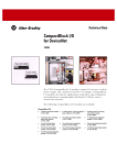
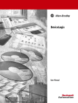
The 1799 Embedded I/O family provides 24V dc digital I/O modules
that can be mounted directly inside a machine in a conveyor rail or
within a field replaceable unit. The 1799 modules contain I/O circuits,
a built-in power supply, and a built-in DeviceNet™ I/O adapter. These
modules are sold as Printed Circuit Board assemblies with optional
hardware available to suit your equipment’s packaging and mounting
needs. The 1799 Embedded I/O modules are ideal for applications
restricted by space limitations, applications requiring highly
distributed I/O close to sensors and actuators, and applications that
have their own enclosures.
2
Overview
The following Embedded I/O modules are available:
1799 Embedded I/O
• 10 universal input/10 sourcing output module
(1799-D10U10B)
• 10 universal input/10 sourcing output module with
DeviceLogix (1799-D10U10BL)
• 10 universal input/10 sinking output module
(1799-D10U10V)
• 10 universal input/10 sinking output module with
DeviceLogix (1799-D10U10VL)
• 16 universal input/16 sourcing output module
(1799-D16U16B)
• 16 universal input/16 sourcing output module with
DeviceLogix (1799-D16U16BL)
• 16 universal input/16 sinking output module
(1799-D16U16V)
• 16 universal input/16 sinking output module with
DeviceLogix (1799-D16U16VL)
• Zone Control I/O 10 input/10 sourcing output module
with DeviceLogix (1799-ZCIOB and 1799-D10U10BZC)
• Zone Control I/O 10 input/10 sinking output module
with DeviceLogix (1799-ZCIOV and 1799-D10U10VZC)
Important User Information
Solid state equipment has operational characteristics differing from those of
electromechanical equipment. Safety Guidelines for the Application,
Installation and Maintenance of Solid State Controls (Publication SGI-1.1
available from your local Rockwell Automation sales office or online at
http://www.ab.com/manuals/gi) describes some important differences
between solid state equipment and hard-wired electromechanical devices.
Because of this difference, and also because of the wide variety of uses for
solid state equipment, all persons responsible for applying this equipment
must satisfy themselves that each intended application of this equipment is
acceptable.
In no event will Rockwell Automation, Inc. be responsible or liable for
indirect or consequential damages resulting from the use or application of
this equipment.
The examples and diagrams in this manual are included solely for illustrative
purposes. Because of the many variables and requirements associated with
any particular installation, Rockwell Automation, Inc. cannot assume
responsibility or liability for actual use based on the examples and diagrams.
No patent liability is assumed by Rockwell Automation, Inc. with respect to
use of information, circuits, equipment, or software described in this manual.
Reproduction of the contents of this manual, in whole or in part, without
written permission of Rockwell Automation, Inc. is prohibited.
Throughout this manual, when necessary we use notes to make you aware of
safety considerations.
WARNING
Publication 1799-TD001C-EN-P - February 2005
Identifies information about practices or circumstances
that can cause an explosion in a hazardous environment,
which may lead to personal injury or death, property
damage, or economic loss.
Overview
IMPORTANT
ATTENTION
3
Identifies information that is critical for successful
application and understanding of the product.
Identifies information about practices or circumstances
that can lead to personal injury or death, property
damage, or economic loss. Attentions help you:
• identify a hazard
• avoid a hazard
• recognize the consequence
SHOCK HAZARD
Labels may be located on or inside the equipment (e.g.,
drive or motor) to alert people that dangerous voltage may
be present.
BURN HAZARD
Labels may be located on or inside the equipment (e.g.,
drive or motor) to alert people that surfaces may be
dangerous temperatures.
ATTENTION
Preventing Electrostatic Discharge
This equipment is sensitive to electrostatic discharge,
which can cause internal damage and affect normal
operation. Follow these guidelines when you handle this
equipment:
• Touch a grounded object to discharge potential static.
• Wear an approved grounding wriststrap.
• Do not touch connectors or pins on component
boards.
• Do not touch circuit components inside the
equipment.
• If available, use a static-safe workstation.
• When not in use, store the equipment in appropriate
static-safe packaging.
Publication 1799-TD001C-EN-P - February 2005
4
Overview
Environment and Enclosure
This equipment is intended for use in a Pollution Degree 2
industrial environment, in overvoltage Category II
applications (as defined in IEC publication 60664-1), at
altitudes up to 2000 meters without derating.
This equipment is considered Group 1, Class A industrial
equipment according to IEC/CISPR Publication 11.
Without appropriate precautions, there may be potential
difficulties ensuring electromagnetic compatibility in other
environments due to conducted as well as radiated
disturbance.
ATTENTION
This equipment is supplied as "open type" equipment. It
must be mounted within an enclosure that is suitably
designed for those specific environmental conditions that
will be present and appropriately designed to prevent
personal injury resulting from accessibility to live parts.
The interior of the enclosure must be accessible only by
the use of a tool. Subsequent sections of this publication
may contain additional information regarding specific
enclosure type ratings that are required to comply with
certain product safety certifications.
See NEMA Standards publication 250 and IEC publication
60529, as applicable, for explanations of the degrees of
protection provided by different types of enclosure. Also,
see the appropriate sections in this publication, as well as
the Allen-Bradley publication 1770-4.1 ("Industrial
Automation Wiring and Grounding Guidelines"), for
additional installation requirements pertaining to this
equipment.
DeviceNet is a trademark of Open DeviceNet Vendor Association (ODVA).
RediSTATION, FLEX I/O, DeviceLink, RSNetWorx for DeviceNet, DeviceNetManager, SoftLogix, and SLC are
trademarks of Rockwell Automation.
PLC is a registered trademark of Rockwell Automation.
Publication 1799-TD001C-EN-P - February 2005
Overview
Overview
5
The 1799 Embedded I/O modules are compatible with PLC®, SLC™ or
SoftLogix™ programmable controllers using DeviceNet scanners. All
Embedded I/O module values are accessible through the data tables
of the PLC or SLC programmable controller.
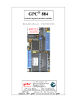
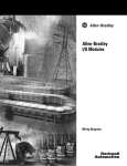
Embedded I/O Module
The DeviceLogix technology is available in the Embedded
I/O family as well. This functionality lets you control outputs and
manage status information locally within the module. This is
accomplished through the DeviceLogix Editor, a function block based
tool that is a part of RSNetWorx for DeviceNet.
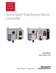
1799-D10
42495
The Zone Control I/O (ZCIO) versions of the Embedded I/O cards
also have Zone Interlocking Parameter (ZIP) that lets the cards
communicate with each other directly. The Zone Control I/O versions
of the Embedded I/O cards include the catalog numbers 1799-ZCIOB,
-ZCIOV, -D10U10BZC, and -D10U10VZC.
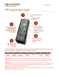
1799-D16
42557
Features and Benefits
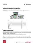
1799-ZCIO
43040
Feature
Benefit
10–30V dc device power
accommodates a broad range of power supplies
and multiple voltage levels from the network
universal NEMA type 1+ inputs
compatible with a broad range of sensors, both
NPN and PNP
output short-circuit protection
protects outputs against accidental miswiring
hardware watchdog function
puts outputs in a known state if the
microprocessor or crystal fails
I/O module located close to sensors
and actuators
lower wiring costs
compact size of I/O module
can be easily embedded directly into a machine
autobaud detection
module automatically matches system baud rate
- no crashing due to incorrect baud setting
rotary node address switches
set module address without software and
therefore reducing node commissioning time
selectable input filters
select off-to-on and on-to-off delays best suited
for your application
change-of-state operation
improves network throughput by reducing
network bandwidth usage
ODVA conformance tested to
DeviceNet version 2.0
assures interoperability with other DeviceNet
compliant devices and systems
DeviceLogix
local logic control
extended temperature specifications
facilitates embedding module within equipment
Publication 1799-TD001C-EN-P - February 2005
6
Overview
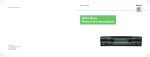
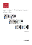
Typical Configuration
This graphic shows how your Embedded I/O fits into a typical
DeviceNet system.
Personal Computer with
configuration software
1799 Embedded I/O
1747-SDN scanner
1784-PCD
PCMCIA card
SLC
controller
FLEX I/O™
Series 9000
Photoelectric
Sensors
1799 Embedded I/O
DeviceLink™ I/O with limit switch
1799 Embedded I/O
42630
System Compatibility
Embedded I/O modules are compatible with PLC, SLC or SoftLogix
programmable controllers when used with DeviceNet scanners.
Embedded Family
Module Communication
The Embedded I/O modules act as a slave in a master/slave
environment. Their I/O data is exchanged with the master through
either a polled, cyclic, or change-of-state connection. The type of
connection is selected in the DeviceNet scanner module's
configuration.
Polled
When configured as a polled device, a master initiates communication
by sending its polled I/O message to the Embedded I/O module.
Cyclic
When using cyclic operation, the master only sends data to the
Embedded I/O module and only receives data from the Embedded
I/O module at a preconfigured time interval.
Publication 1799-TD001C-EN-P - February 2005
Overview
7
Change-of-State
With a change-of-state connection, data changes are automatically
sent to the master, i.e., the master no longer has to request data. In
addition, the Embedded I/O module periodically produces an
adjustable ‘heartbeat’ to let the master device know that the module
connection is alive and ready to communicate.
When an Embedded I/O module is configured for change-of-state, the
master only sends output data when the user's control program wants
to update the module's outputs.
The Embedded I/O module's input and any fault status is only sent to
the master when an input or any fault status changes.
Input Filtering
Input filtering limits the effect of voltage transients caused by contact
bounce and/or electrical noise. If not filtered, voltage transients could
produce false data.
To configure an input filter, an input signal delay is set to turn
off-to-on or on-to-off for nominal amounts of time (0, 2, 4, 8, or 16
ms). When an input transitions from off-to-on, it must remain on for
the specified amount of time before the module considers it.
The mode and filter time is set through RSNetWorx for DeviceNet,
DeviceNetManager™ software or a similar configuration tool.
AutoBaud Detect
The Embedded I/O modules have an AutoBaud Detect feature. These
modules automatically sense the baud rate of the network they are
connected to and adjust the module’s communication rate
accordingly. You can disable the AutoBaud feature through your
configuration software.
Publication 1799-TD001C-EN-P - February 2005
8
Overview
Idle and Fault
Mode Selection
When the PLC, SLC or PC-based programmable controller is in
program mode, the DeviceNet scanner puts the Embedded module in
an idle state. If the DeviceNet scanner drops off the network, the
module goes to a fault state.
In both idle and fault states, the module resets its outputs by default.
Use RSNetWorx for DeviceNet software or a similar configuration tool
to change the default and set the module to save the last received
outputs.
Fault
State
hold last state (HLS)
HLS
use fault value
Fault
Value
0
1
apply 0 to output
apply 1 to output
The fault state can be set to HLS or use the fault value. The fault value can
be set to 0 or 1. The same logic applies for idle conditions.
42455
The Embedded I/O module is designed to let you select how its
outputs will respond to either a Network Communication Fault or
placing the controller in program mode (idle state). To have the
module respond in the desired manner, you must configure the Fault
State parameter of the Embedded module to hold last state. If you
elect not to enable hold last state, the module will defer to the Fault
Value parameter.
The Fault Value parameter is where you select either 0 or 1 as the
Communication Fault value. The default value is 0.
DeviceLogix Functionality
Publication 1799-TD001C-EN-P - February 2005
The Embedded I/O family also offers modules that have DeviceLogix,
a local logic capability that provides you with the ability to control
outputs and manage status information locally within the device.
DeviceLogix is configured through a Function Block Editor that is
accessed through RSNetWorx for DeviceNet. This editor lets you
create local logic using boolean logic (AND, OR, etc.), set and reset
latches, as well as a variety of timers and counters. For more
information about the editor, refer to the DeviceLogix User Manual,
publication number ACIG-UM001, and online help.
Overview
9
Embedded I/O products that support DeviceLogix have some
device-specific capabilities and capacities, which are identified in the
DeviceLogix Capabilities and Capacities table.
DeviceLogix Capabilities and Capacities
Capability/Capacity
Embedded I/O
• boolean
function blocks supported
• latches
• timers
• counters
maximum number of function
blocks included in a configuration
48
ZCIO Card
72
function block processing time
2msec/24 blocks
4msec/48 blocks
ZCIO Card
6msec/72 blocks
network input bits
32
network output bits
8
available fault bits
output fault (16U16B/BL only)
available status bits
• explicit message connection
• polled connection
• change-of-state/cyclic connection
• change-of-state/cyclic fault
• network fault
• minor module fault
logic status indication
• none
• logic disabled
• solid green
• logic enabled
• flashing green
• local forces are applied and local logic is enabled
Publication 1799-TD001C-EN-P - February 2005
10
Overview
Zone Interlocking Parameter
Zone Interlocking Parameter provides the means for a Zone Control
card to consume data directly from up to four other Zone Control
cards without going through a scanner. This enables the fast transfer
of information from one conveyor zone using a Zone Control card to
the next. For example, a Zone Control card could consume data from
the previous Zone Control card in a conveyer then provide data to a
three lane diverter that follows. This interaction is configured through
a series of new parameters in the EDS file for the device. These
parameters include the MacID of the producing device, masks and
offsets to put the data where you want it to be, and data security
parameters to ensure against timeouts and bad data.
The data consumed from a Zone Control device will be used in a
DeviceLogix program. It will appear in the DeviceLogix Editor as
Zone Data in the Network Inputs pulldown boxes. They can be used
as any other Network Input would be used. For more information
about ZIP, see the Zone Interlocking Parameters section.
Optional I/O Assemblies
The DeviceLogix-capable versions of Embedded I/O lets you choose
how much data the modules produce or consume over DeviceNet.
Two parameters in the EDS files let you select the amount of data that
will be transmitted or received.
Note that for the ZCIO cards, you can select only the consumed I/O
assembly size. The produced size is fixed at 7 bytes.
Produced I/O Assembly
There are three options for Produced Data:
• Default assembly - Produces the device’s input data and any
fault/status data the device has.
• Input only assembly - Produces only the state of the device’s
inputs. This lets those who do not make use of the diagnostic
bits to reduce their network traffic.
• DeviceLogix assembly - Produces all of the standard
information from the default assembly plus the data that is
available as a result of invoking DeviceLogix.
Publication 1799-TD001C-EN-P - February 2005
Overview
11
The DeviceLogix data that is available includes:
– Logic Enabled bit - This bit is high when DeviceLogix is
running a device and when DeviceLogix has been enabled. This
bit can be used, for example, in the PLC program or on a
DeviceNet MMI to indicate the presence of local logic control.
– Eight Network Output bits - These bits are used in the
DeviceLogix configuration to send information back over the
network. The output of any function block can be connected to
a network output bit.
– Hardware Output bits - DeviceLogix lets you locally control
the state of hardware outputs. Therefore, these bits are
produced by the device so that the state of the outputs can be
sent back to the network master. If an output in the device is not
under DeviceLogix control, its status is still controlled by the
normal consumed data.
DeviceLogix Assemblies for Embedded I/O devices:
1799-D10U10BL and 1799-D10U10VL
Bit 7
Bit 6
Bit 5
Bit 4
Bit 3
Bit 2
Bit 1
Bit 0
Byte 0
In 7
In 6
In 5
In 4
In 3
In 2
In 1
In 0
Byte 1
Reserved
Logic Ena
In 9
In 8
Byte 2
Out 7
Out 6
Out 1
Out 0
Out 9
Out 8
Reserved
Out 5
Byte 3
Byte 4
Out 4
Out 3
Out 2
Reserved
NetOut 7
NetOut 6
NetOut 5
NetOut 4
NetOut 3
NetOut 2
NetOut 1
NetOut 0
Logic Ena = DeviceLogix Enabled, NetOut = Network Output
1799-D16U16BL
Bit 7
Bit 6
Bit 5
Bit 4
Bit 3
Bit 2
Bit 1
Bit 0
Byte 0
In 7
In 6
In 5
In 4
In 3
In 2
In 1
In 0
Byte 1
In 15
In 14
In 13
In 12
In 11
In 10
In 9
In 8
Byte 2
Reserved Logic Ena
OFLT 1
OFLT 0
Byte 3
Out 7
Out 6
Out 5
Out 4
Out 3
Out 2
Out 1
Out 0
Byte 4
Out 15
Out 14
Out 13
Out 12
Out 11
Out 10
Out 9
Out 8
Byte 5
NetOut 7
NetOut 6
NetOut 5
NetOut 4
NetOut 3
NetOut 2
NetOut 1
NetOut 0
Reserved
Logic Ena = DeviceLogix Enabled, OFLT 0 = Output Fault on one or more outputs in GRP 0,
OFLT 1 = Output Fault on one or more outputs in GRP 1, NetOut = Network Output
Publication 1799-TD001C-EN-P - February 2005
12
Overview
1799-D16U16VL
Bit 7
Bit 6
Bit 5
Bit 4
Bit 3
Bit 2
Bit 1
Bit 0
Byte 0
In 7
In 6
In 5
In 4
In 3
In 2
In 1
In 0
Byte 1
In 15
In 14
In 13
In 12
In 11
In 10
In 9
In 8
Byte 2
Reserved Logic Ena
Byte 3
Out 7
Out 6
Out 5
Out 4
Out 3
Out 2
Out 1
Out 0
Byte 4
Out 15
Out 14
Out 13
Out 12
Out 11
Out 10
Out 9
Out 8
Byte 5
NetOut 7
NetOut 6
NetOut 5
NetOut 4
NetOut 3
NetOut 2
NetOut 1
NetOut 0
Reserved
Logic Ena = DeviceLogix Enabled, NetOut = Network Output
Consumed I/O Assembly
DeviceLogix lets the device consume data from the DeviceNet master
in a manner other than the normal state of the hardware outputs. This
data is called Network Input bits. The device can consume up to 32 of
these bits. Five options exist for the variable amount of consumed
data: 0, 1, 2, 3, or 4 bytes. A standard Embedded I/O module, for
instance, consumes 16 bits (2 bytes). With DeviceLogix, you can
choose to consume an additional 2 bytes of network inputs. If a
hardware output is controlled by local logic, its state is no longer
consumed and that bit becomes available to be used as a network
input. For more information on this concept, please see the
DeviceLogix User Manual, publication number ACIG-UM001.
Publication 1799-TD001C-EN-P - February 2005
Overview
Zone Interlocking
Parameters
13
Zone Interlocking Parameter (ZIP) is a method of having Zone
Control cards share data directly without hard wiring them together
and without using a scanner. One Zone Control card can consume
data from up to four other Zone Control cards. A consumer of ZIP
data can also produce ZIP data to another Zone Control card.
Change-of-state data can only be consumed from other Zone Control
cards. Other devices can reside on the network and can be
communicated with normally. Data from a Zone Control card can still
be accessed by a controller or EOI as in any other application through
an explicit or polled connection. A total of 8 bytes of data can be
consumed per Zone Control card. This data can be configured as 2
bytes from each of four cards or up to 5 bytes from a single card.
Mask and offset parameters have been provided to let you pick the
data you want to consume from each Zone Control card and pack it
where you want to within the 8 bytes available. Expected Packet Rate
and Production Inhibit Time parameters are also provided. One more
feature is a Data Security Key that, if enabled, lets you check that the
device being consumed from is the right device and has the expected
configuration. The following sections provide details about the
parameters and explains how to implement them.
ZCIO Data Production
Each Zone Control card will produce 7 bytes. The produced assembly
is as follows:
1799-ZCIOB, 1799-D10U10BZC, 1799-ZCIOV, and 1799-D10U10VZC
Bit 7
Bit 6
Bit 5
Bit 4
Bit 3
Bit 2
Bit 1
Bit 0
Produced 0
Input 7
Input 6
Input 5
Input 4
Input 3
Input 2
Input 1
Input 0
Produced 1
Reserved Logic Ena
Input 9
Input 8
Produced 2
Output 7 Output 6 Output 5 Output 4 Output 3 Output 2 Output 1 Output 0
Produced 3
Reserved
Reserved
Output 9 Output 8
Produced 4
NetOut 7 NetOut 6 NetOut 5 NetOut 4 NetOut 3 NetOut 2 NetOut 1 NetOut 0
Produced 5
CCV 7
CCV 6
CCV 5
CCV 4
CCV 3
CCV 2
CCV 1
CCV 0
Produced 6
CCV 15
CCV 14
CCV 13
CCV 12
CCV 11
CCV 10
CCV 9
CCV 8
NetOut = Network Output (0-7), CCV = Configuration Consistency Value (0-15), shown in Parameter 40
Therefore, the production data size will always be 7. The last two
bytes (Produced 5 & 6) are used to calculate the Module Security Key
value and are not accessible as Zone Control data.
Publication 1799-TD001C-EN-P - February 2005
14
Overview
ZCIO Data Parameters
A total of 8 bytes of data can be consumed by each Zone Control
card. Use the ZCIO data parameters to determine how much and what
data is available from each Zone Control card.
Please note that if the application is running without a master,
Autobaud (Parameter 1) must be disabled on at least one of the Zone
Control modules. The 1799-D10U10BZC and 1799-D10U10VZC cards
have 5 additional parameters for relative consumed address
implementation. This changes the parameter order for those cards.
Control Parameters
Parameter 13: AutoRun ZIP - Parameter 13 lets the producing device
automatically create and configure an unacknowledged change-ofstate I/O connection at powerup. This lets you set up a network of
devices without using a scanner. This parameter is disabled by default.
It must be enabled in a producing ZCIO if no scanner is used to
communicate with the producer. A consuming ZCIO needs to have
this parameter enabled only if it is also a producer. Power must be
cycled or a reset sent to the ZCIO for this change to take affect.
Parameter 42 or 47: Zone Control Enable - The Zone Control Enable
parameter lets you enable or disable the Zone Control functionality for
the entire device. The parameter is disabled by default. Zone Control
must first be disabled before any other Zone Control changes are
made and DeviceLogix must be in the Logic Disabled state for this
parameter to take affect. An Enable message will be rejected if
DeviceLogix is enabled or a parameter setup error, such as a masking
or data offset error, is detected.
Timing Parameters
Parameter 14: Zone Produced Heartbeat - This parameter defines in
milliseconds the heartbeat time associated with this module’s
production. If no data has changed for a period equal to this Expected
Packet Rate (EPR), the producing Zone Control will send old data to
let consuming connections know that it is still alive.
Publication 1799-TD001C-EN-P - February 2005
Overview
15
Parameter 32-35 or 37-40: Zone Connection # (1-4) - EPR - The EPR
parameter will let you set the Expected Packet Rate, in milliseconds,
from the producing device. The default EPR is 75. If the consumer
does not hear from the producer in 4 times the EPR, it will drop the
connection and attempt to open a new connection during subsequent
scan cycles. Note that the consuming EPR should match the value of
the producer’s EPR.
Parameter 15: Zone Produced PIT - The PIT parameter lets you set the
Production Inhibit Time of the Zone Control card’s producing
connection. This limits how often the producer is allowed to send
data to the consumer. The producer must wait until the PIT expires
before sending new data. If it is set to 0, the producer can send data
anytime it changes. The default is set to 1 msec.
Data Management Parameters
Data management parameters map zone data into the Zone Control
card’s 8-byte data space. This is similar to mapping data in a
DeviceNet scanner. Mapping errors can prevent Zone Control from
enabling.
Parameter 16 (1799-10U10BZC and 1799-10U10VZC only): Relative
MacID Offset - Parameter 16 lets the consumed node address be set
relative to the consuming modules’s node. The default is Enabled.
Parameters 16-19 or 21-24 Zone Connection #(1-4) MacID - This is the
DeviceNet MacID number for each Zone Control card from which the
device wants to consume data. The default is set to 64. Setting this
parameter back to 64 disables the consumption of data.
Parameter 17-20 (1799-10U10BZC and 1799-10U10VZC only): Zone
Connection #(1-4) MacID Offset - This parameter is the offset that
determines the DeviceNet MacID number for each Zone Control card
from which the device consumes data. The default is Invalid value.
Setting this parameter to Invalid value disables the consumption of
data on this connection. The range is consumers MacID -4 to
consumers MacID 4.
Publication 1799-TD001C-EN-P - February 2005
16
Overview
Parameters 24-27 or 29-32: Zone Connection # (1-4) Mask - A mask
parameter is provided that lets you select the consumed bytes in
which you are interested. For example, a Zone Control may need only
the first and fifth bytes of consumed data for the application from a
particular Zone Control card, as shown in the illustration.
Parameters 28-31 or 33-36: Zone Connection # (1-4) Offset - An offset
parameter is provided that lets you place the consumed data in the
8-byte data space reserved in the consuming device. For example, you
may want to put the 2 bytes of data from address 10 into the third and
fourth byte of the data space. This would lead to an offset of 2 being
set. Offset conflict errors will prevent Zone Control from enabling.
Data Security Parameters
Parameters 20-23 or 25-28: Zone Connection # (1-4) Health - This
parameter indicates whether the connection between this Zone
Control card and the one with the corresponding MacID is healthy.
This parameter will indicate Not Healthy if the connection between
the producer and consumer fails or if the Data Security Key is enabled
and doesn’t match the value loaded for that connection (see the
description for Parameter 41, Data Security).
Parameters 36-39 or 41-44: Cnxn 1-4 Security Key Value - If Data
Security Parameter is enabled, take the value from the Module
Security Key Value parameter of the producing device and enter it into
this parameter. The consuming connection will validate the key
received on each data packet against the stored value.
Parameter 40 or 45: Module Security Key Value - This value is
calculated for this module based on the configuration resident in the
module. If Data Security is enabled in a consuming Zone Control card,
this number is entered into the Data Security Key Parameter on the
consuming module, as noted in the description of Parameters 36-39.
Publication 1799-TD001C-EN-P - February 2005
Overview
17
Parameter 41 or 46: Data Security - This parameter enables Data
Security on a consuming module. Enabling this parameter and placing
the producer’s Data Security Key value in the consumer’s Cnxn x
Security Key Value (Parameters 36-39) assures that the configuration in
the producing device is the one that the consumer is expecting. This
protects against a module being replaced and not having the correct
parameters set or the DeviceLogix configuration being loaded
improperly. This parameter is enabled by default.
Interaction With DeviceLogix
Once the data has been configured in the consuming ZCIO and
enabled, it is ready for deployment in the DeviceLogix Editor.
ZIP Data Bits
The ZIP bits that are available will be shown in the Network Inputs
pulldown menu immediately after the listing of the Network Inputs, as
shown in the illustration.
The bits are then placed on the DeviceLogix programming grid in the
same manner as other inputs.
ZIP Connection Status
ZIP Connection Status bits are available through the Module Status
Points pulldown menu in the DeviceLogix Editor. Two bits will be
available for each of the 4 Zone Connections - Zone Connection #
(1-4) Exists and Zone Connection # (1-4) Data Valid. These bits can be
used in the logic to alter the status of the outputs under local control
depending on the health of the ZIP connection. If a connection faults,
the consuming ZCIO will attempt to re-establish a connection during
the subsequent scan cycle.
Publication 1799-TD001C-EN-P - February 2005
18
Overview
ZIP Data Example
Below is an example of a ZCIO configuration. In this instance, the
consumer is MacID 26 and the producers are MacIDs 25, 27, 28, and
29.
Offset Position In ZIP Data
Table, Parameter (28-31)
Address Of Producing
Device Parameter (16-19)
Byte From Producer Chosen
By Mask Parameter (24-27)
Byte 0
MacID 25
Byte 3
Byte 1
MacID 27
Byte 4
Byte 2
MacID 28
Byte 0
Byte 3
MacID 29
Byte 2
Byte 4
Not Used
Not Used
Byte 5
Not Used
Not Used
Byte 6
Not Used
Not Used
Byte 7
Not Used
Not Used
This ZIP data table will not be visible, but the individual bits are
available for use in DeviceLogix as Zone Data, as noted.
Publication 1799-TD001C-EN-P - February 2005
Overview
19
The produced assembly makes the following data available to the
consuming ZCIO:
MacID
MacID
MacID
MacID
25
27
28
29
Output 8, Output 9 (other bits are unused)
Network Output 0-7
Input 0-7
Output 0-7
In DeviceLogix, the bits will appear as follows:
The ZIP data can be used as an input to any Function Block, as can
any of the ZIP Connection Status Bits.
Please note that comments are entered manually. Use comments to
trace the source of the data.
Publication 1799-TD001C-EN-P - February 2005
20
Overview
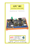
Status Indicators
Each Embedded I/O module has indicators to provide a diagnostic
readout.
I/O Status Indicator
Board Status Indicator
DeviceLogix Status Indicator
Network Status Indicator
1799-D10
1799-D16
42509
Board Status Indicator
Auxiliary Power
Status Indicator
DeviceLogix Status Indicator
Network Status Indicator
I/O Status Indicator
1799-ZCIO
I/0 Status
Indicators
43045
Auxiliary Power
Status Indicator
Network Status
DeviceLogix
Indicator
Status Indicator
Publication 1799-TD001C-EN-P - February 2005
Card Status
Indicator
42567
Overview
21
Network Status Indicators
Indication
Status
Off
Not powered/Not online - Device is not online.
• The device has not completed the duplicate MacID test.
• The device is not powered.
Green
Online, connected - Device is operating normally and is online with
connections established.
Flashing green
Online, not connected:
• Device is online with no connections established.
• The device has passed duplicate MacID tests, but has not
established connections to other nodes.
Red
Critical link failure - Failed communication device
The device has detected an error and has been rendered incapable of
network communication.
Flashing red
Connection timed-out - An I/O connection has timed-out.
Communication previously established with the master has been lost.
Board/Card Status Indicators
Indication
Status
Off
No power - No power applied to the module.
Green
Device operational - Module is operating normally.
Flashing green
Needs commissioning - The module has a missing, incomplete, or an
incorrect commissioning.
Flashing red
Minor fault - Recoverable fault has occurred.
Red
Critical fault - Watchdog timeout or the module has an unrecoverable
fault and may need replacing.
Logic Status Indicators
Indication
Status
Off
Logic is disabled.
Solid green
Logic is enabled.
Flashing green
Local forces are applied and local logic is enabled.
Publication 1799-TD001C-EN-P - February 2005
22
Overview
I/O Status Indicators
Indication
Status
Outputs
None
Output not energized
Yellow
Output energized
Inputs
None
No valid input
Yellow
Valid input
Auxiliary Power Status Indicator
Power Supply
Requirements
Indication
Status
None
No auxiliary power
Green
Auxiliary power present
The DeviceNet network supplies power to the Embedded
I/O modules. Inputs and outputs are powered by an external 24V dc
source which is independent of the network.
Auxiliary Power Specifications
The power source used to supply the auxiliary power to the outputs
must be one of the following:
• a 10-30V dc Class 2 Power Supply
or
• a 10-30V dc Class 2 Power Supply or a 10-30V dc UL Listed or
Recognized Power Supply with isolated outputs limited to 200
volt-amperes in each ungrounded output line. This condition
requires that the board and power source be mounted in a
suitable ultimate enclosure with proper spacings maintained.
Publication 1799-TD001C-EN-P - February 2005
Overview
Mount the 10 Input/
10 Output Board
23
The Embedded I/O module can be mounted directly to a panel or on
a DIN rail, using the appropriate accessory items.
Mount the Board and Optional Cover
Use the illustrations to help you mount the board to a DIN rail using
DIN rail brackets (1799-BRKD) or to a mounting plate (1799-MP20).
Mount the 10 Input/10 Output Board
DIN rail
DIN rail bracket
or
or
mounting plate
0.95in.
24.13mm
2.10in.
53.34mm
plastic cover
42507
The board can also be mounted in an enclosure with pre-tapped
holes, which accommodate M3 x 0.5 mm screws.
Note that with the addition of the cover, the width of the board
increases from 2.0 in. to 2.10 in. (50.8 mm to 53.34 mm) and the
height increases from 0.75 in. to 0.95 in.(19.05 mm to 24.13 mm).
Publication 1799-TD001C-EN-P - February 2005
24
Overview
Board Dimensions
3.00in.
76.20mm
3.90in.
99.00mm
0.45in.
11.43mm
2.0in.
50.80mm
0.75in.
19.05mm
1.08in.
27.30mm
0.63in.
15.88mm
6.40in.
162.56mm
42506
Mounting Plate Dimensions (front view)
7.00in.
177.8mm
2.10in.
53.34mm
0.13in.
3.30mm
1.05in.
26.67mm
42562
0.75in.
19.05mm
Publication 1799-TD001C-EN-P - February 2005
Overview
Mount the 16 Input/
16 Output Board
25
Mount the Board and Optional Cover
Use the pictures to help you mount the board to a DIN rail using DIN
rail brackets (1799-BRKD) or to a mounting plate (1799-MP32). The
board can also be mounted in an enclosure with pre-tapped holes,
which accommodate M3 x 0.5 mm screws.
Mount the 16 Input/16 Output Board
DIN rail
DIN rail bracket
or
or
0.62in.
15.62mm
mounting plate
3.69in.
93.73mm
plastic cover
42559
Note that with the addition of the cover, the width of the board
increases from 3.07 in. to 3.69 in. to (77.85 mm 93.73 mm) and the
height increases from 0.75 in. to 1.38 in. (19.05 mm to 35.05 mm).
Publication 1799-TD001C-EN-P - February 2005
26
Overview
Board Dimensions
4.75in.
120.65mm
0.14in.
3.53mm
3.85in.
97.79mm
0.45in.
11.43mm
0.05in.
1.73mm
0.75in.
19.05mm
3.07in.
77.85mm
1.18in.
29.85mm
1.15in.
29.21mm
7.40in.
187.96mm
42560
Mounting Plate Dimensions (front view)
8.25in.
209.55mm
1.62in.
41.15mm
3.06in.
38.61mm
0.13in.
3.30mm
1.52in.
38.61mm
42562
Publication 1799-TD001C-EN-P - February 2005
Overview
Mount the Zone
Control Card
27
Mount the Card and Optional Cover
The ZCIO card comes with a mounting plate. You have the option to reset
the DIN rail brackets (1799-BRKD) for mounting directly on a DIN rail.
Mount the ZCIO Card
DIN rail
DIN rail bracket
or
or
0.95in.
24.13mm
mounting plate
2.10in.
53.34mm
plastic cover
43041
The card can also be mounted in an enclosure with pre-tapped holes,
which accommodate M3 x 0.5 mm screws.
Note that with the addition of the cover, the width of the board
increases from 2.0 in. to 2.10 in. (50.8 mm to 53.34 mm) and the
height increases from 0.75 in. to 0.95 in.(19.05 mm to 24.13 mm).
Publication 1799-TD001C-EN-P - February 2005
28
Overview
Card Dimensions
3.90in.
99.00mm
3.00in.
76.20mm
0.45in.
11.43mm
0.75in.
19.05mm
0.63in.
15.88mm
2.0in.
50.80mm
43042
1.08in.
27.30mm
Publication 1799-TD001C-EN-P - February 2005
6.40in.
162.56mm
Overview
Embedded I/O Accessories
29
The Embedded I/O Optional Hardware table lists part numbers and
descriptions for optional hardware.
Optional Hardware
All mating connectors and mounting hardware must be ordered
separately. The Embedded I/O Optional Hardware table identifies the
different connector and hardware options.
Embedded I/O Optional Hardware
Option
Catalog
Number
Third Party Supplier & Part Number
Used With
2 DIN rail brackets (4 screws)
1799-BRKD
N/A
All
clear plastic cover (4 stand-offs, 4 screws)
1799-COV20
N/A
10 in/10 out
clear plastic cover (4 stand-offs, 4 screws)
1799-COV32
N/A
16 in/16 out
clear plastic cover (4 stand-offs, 4 screws)
1799-COVZC
N/A
ZCIOB
ZCIOV
D10U10BZC
D10U10VZC
mounting plate (4 screws)
1799-MP20
N/A
10 in/10 out
2, 12-position, gold-plated I/O mating connectors
1799-12SPCON
Phoenix - FK-MC 0.5/12-ST-2.5AU - 1923432 10 in/10 out
5-position, open-style plug for DeviceNet
1799-DNETCON
DeviceNet Buyer’s Guide at
http://www.odva.org
10 in/10 out
5-position, open-style plug/locking screws for
DeviceNet
1799-DNETSCON DeviceNet Buyer’s Guide at
http://www.odva.org
16 in/16 out
2-position plug for auxiliary power
1799-AUXCON
Weidmuller - 171385
PCD - ELFP02211
10 in/10 out
50-pin, D-sub I/O mating connector - solder cup
1799-DSSCON
Amphenol Corp. - 777DF-D50P
ITT Cannon - DDM50PK127
16 in/16 out
50-pin, D-sub I/O mating connector - header and
crimp pins
1799-DSCCON
Tyco Electronics - 205212-1 (header)
Tyco Electronics - 66506-4 (pins)
EBY Co. - DR50-P02-0S (header only)
16 in/16 out
mounting plate (4 screws)
1799-MP32
N/A
16 in/16 out
Publication 1799-TD001C-EN-P - February 2005
30
Overview
Specific Module
Information
The remainder of this publication contains specification information
for each Embedded I/O module. Refer to the table below for
information about a specific module.
For information about
See page
10 universal input/10 sourcing output module (1799-D10U10B) and
10 universal input/10 sinking output module (1799-D10U10V)
31
10 universal input/10 sourcing output module with DeviceLogix (1799-D10U10BL) and
10 universal input/10 sinking output module with DeviceLogix (1799-D10U10VL)
37
16 universal input/16 sourcing output module (1799-D16U16B) and
16 universal input/16 sourcing output module with DeviceLogix (1799-D16U16BL)
43
16 universal input/16 sinking output module (1799-D16U16V) and
16 universal input/16 sinking output module with DeviceLogix (1799-D16U16VL)
49
10 input/10 sourcing output module with DeviceLogix (1799-ZCIOB) and
10 input/10 sinking output module with DeviceLogix (1799-ZCIOV)
55
10 input/10 sourcing output module with DeviceLogix (1799-D10U10BZC) and
10 input/10 sinking output module with DeviceLogix (1799-D10U10VZC)
61
Related Publications
Refer to the following list of publications for more information about
the DeviceNet network, DeviceNet products, and DeviceLogix.
Title
Publication Number
DeviceNet Product Overview
DN-2.5
DeviceNet Media Design Installation Guide
DNET-UM072
DeviceLogix User Manual
ACIG-UM001
Refer to the installation instructions for your product for information
on input and output connections, wiring instructions, torque
specifications, and other installation instructions.
Publication 1799-TD001C-EN-P - February 2005
1799-D10U10B or 1799-D10U10V Module
31
1799-D10U10B or 1799-D10U10V Module
Communication Information
This board exchanges I/O with the master on DeviceNet through a
cyclic, polled, or change-of-state connection. See the
1799-D10U10B/-D10U10V Consume and Produce Data table for more
information.
1799-D10U10B/-D10U10V Consume and Produce Data
I/O Connection Type
Consumes
Produces
Cyclic
2 Bytes
2 Bytes
Polled
2 Bytes
2 Bytes
Change-of-State
2 Bytes
2 Bytes
Cyclic - the board will produce and consume its
I/O cyclically at the rate configured by the master on DeviceNet.
Polled - the master initiates communication by sending its polled I/O
message to the board. The board consumes the message, updates any
outputs and produces a response containing the input data.
Change-of-State - a production occurs when an input changes. A
heartbeat production occurs if no input condition change occurs
within the expected packet rate. This heartbeat production tells the
master that the board is alive and ready to communicate.
Consumption occurs when data changes and the master produces
new output data to the board.
See the 1799-D10U10B/-D10U10V Word/Bit table for the word/bit
definitions.
1799-D10U10B/-D10U10V Word/Bit Table
Byte
Bit 7
Bit 6
Bit 5
Bit 4
Bit 3
Bit 2
Bit 1
Bit 0
Produced 0
In 7
In 6
In 5
In 4
In 3
In 2
In 1
In 0
In 9
In 8
Out 1
Out 0
Out 9
Out 8
Produced 1
Consumed 0 Out 7
Consumed 1
Reserved
Out 6
Out 5
Out 4
Reserved
Out 3
Out 2
Publication 1799-TD001C-EN-P - February 2005
32
1799-D10U10B or 1799-D10U10V Module
Troubleshooting Indicators
This board has the following indicators:
•
•
•
•
Board status
Network status
Auxiliary power
I/O status
Board Status Indicator (labeled MOD)
1799-D10U10B and 1799-D10U10V Board Status Indicator Descriptions
Indication
Status
Off
No power - No power applied to the module.
Green
Device operational - Module is operating normally.
Flashing green
Needs commissioning - The module has a missing, incomplete, or an
incorrect commissioning.
Flashing red
Minor fault - Recoverable fault has occurred.
Red
Critical fault - Watchdog timeout or the module has an unrecoverable
fault and may need replacing.
Network Status Indicator (labeled NET)
1799-D10U10B and 1799-D10U10V Network Status Indicator Descriptions
Indication
Status
Off
Not powered/Not online - Device is not online.
• The device has not completed the duplicate MacID test.
• The device is not powered.
Green
Online, connected - Device is operating normally and is online with
connections established.
Flashing green
Online, not connected:
• Device is online with no connections established.
• The device has passed duplicate MacID tests, but has not
established connections to other nodes.
Publication 1799-TD001C-EN-P - February 2005
Red
Critical link failure - Failed communication device
The device has detected an error and has been rendered incapable of
network communication.
Flashing red
Connection timed-out - An I/O connection has timed-out.
Communication previously established with the master has been lost.
1799-D10U10B or 1799-D10U10V Module
33
Auxiliary Power Indicator (labeled AUX PWR)
1799-D10U10B and 1799-D10U10V Auxiliary Power Status Indicator Descriptions
Indication
Status
None
No auxiliary power
Green
Auxiliary power present
I/O Status Indicators (labeled Inputs and Outputs)
1799-D10U10B and 1799-D10U10V I/O Status Indicator Descriptions
Indication
Status
Outputs
None
Output not energized
Yellow
Output energized
Inputs
Specifications
None
No valid input
Yellow
Valid input
Specifications are listed below.
10 Input/10 Output Board - Cat. No. 1799-D10U10B or 1799-D10U10V Specifications
Input Specifications
Max.
Min.
Inputs per block
10 Sinking or Sourcing, Type 1 + compatible
Off-State
Voltage
Current
5V dc
1.5 mA
-
On-State
Voltage
Current
30V dc
6 mA
10V dc
2 mA
Output Specifications
Max.
Min.
Outputs per block
10 Sourcing, 0.5 A, Short Circuit Protected, Pilot Duty
Output Auxiliary Voltage
30V
10V
On-State Voltage Drop
250 mV
-
On-State Current
0.5 A
-
Off-State Leakage
20 µA
-
Board Current (all outputs on)
4.0 A
-
Publication 1799-TD001C-EN-P - February 2005
34
1799-D10U10B or 1799-D10U10V Module
10 Input/10 Output Board - Cat. No. 1799-D10U10B or 1799-D10U10V Specifications
General Specifications
Max.
Min.
Surge Current - for 10ms, repeatable
every 2s (individual outputs)
1.0 A
-
DeviceNet Power
Voltage
Current
25V dc
125 mA
11V dc
-
Auxiliary Power
Voltage
Current
30V dc
4.3 A (all outputs on)
10V dc
100 mA (all outputs off)
DeviceNet Power Circuit Type
Class 2
LED Indicators
Board Status - red/green
Network Status - red/green
Auxiliary Status - green
Input Point Status - yellow
Output Point Status -yellow
Dimensions
inches (millimeters)
1.0H x 2.0W x 6.4D
(26H x 51W x 163D)
Operational Temperature
IEC 60068-2-1 (Test Ad, Operating Cold),
IIEC 60068-2-2 (Test Bd, Operating Dry Heat),
IEC 60068-2-14 (Test Nb, Operating Thermal Shock):
-10 to 60o C (14 to 140o F)
Storage Temperature
IEC 60068-2-1 (Test Ab, Un-packaged Non-operating Cold),
IEC 60068-2-2 (Test Bb, Un-packaged Non-operating Dry Heat),
IEC 60068-2-14 (Test Na, Un-packaged Non-operating Thermal Shock):
-40 to 85o C (-40 to 185o F)
Relative Humidity
IEC 60068-2-30 (Test Db, Un-packaged Non-operating Damp Heat):
5 to 95% non-condensing
Vibration
IEC 60068-2-6 (Test Fc, Operating):
5g @ 10-500Hz
Operating Shock
IEC 60068-2-27 (Test Ea, Unpackaged Shock):
30g
Non-Operating Shock
IEC 60068-2-27 (Test Ea, Unpackaged Shock):
50g
Emissions
CISPR 11:
Group 1, Class A
ESD Immunity
IEC 61000-4-2:
6kV indirect contact discharges
Radiated RF Immunity
IEC 61000-4-3:
10V/m with 1kHz sine-wave 80%AM from 30MHz to 1000MHz
10V/m with 200Hz 50% Pulse 100%AM at 900MHz
EFT/B Immunity
IEC 61000-4-4:
±2kV at 5kHz on power ports
±4kV at 2.5kHz on signal ports
±2kV at 5kHz on communications ports
Publication 1799-TD001C-EN-P - February 2005
1799-D10U10B or 1799-D10U10V Module
35
10 Input/10 Output Board - Cat. No. 1799-D10U10B or 1799-D10U10V Specifications
General Specifications (Continued)
Surge Transient Immunity
IEC 61000-4-5:
±2kV line-earth(CM) on power ports
±2kV line-line(DM) and ±4kV line-earth(CM) on signal ports
±2kV line-earth(CM) on communication ports
Conducted RF Immunity
IEC 61000-4-6:
10Vrms with 1kHz sine-wave 80%AM from 150kHz to 80MHz
Enclosure Type Rating
None (open-style)
Auxiliary Supply Power Rating
Isolated outputs limited to 200 volt-amperes in each ungrounded output line
Isolation voltage
(continuous-voltage withstand rating)
Tested to withstand 1000V dc for 60 seconds
Conductors Wire Size1
DeviceNet Power: 14 gauge (2mm2) stranded maximum
Auxiliary Power: 14 gauge (2mm2) stranded maximum
DeviceNet: 14 gauge (2mm2) stranded maximum (See Publication DNET-UM072)
I/O: 20 AWG to 24 AWG
Wiring Category1
1 - on signal ports
1 - on power ports
2 - on communications ports
Wire Type
Copper
Certifications:2
(when product is marked)
c-UR-us
CE
C-Tick
ODVA
UL Recognized Component Industrial Control Equipment,
certified for US and Canada
European Union 89/336/EEC EMC Directive, compliant with:
EN 50082-2; Industrial Immunity
EN 61326; Meas./Control/Lab., Industrial Requirements
EN 61000-6-2; Industrial Immunity
EN 61000-6-4; Industrial Emissions
EN 61131-2; Programmable Controllers (Clause 8, Zone A & B)
Australian Radiocommunications Act, compliant with:
AS/NZS CISPR 11; Industrial Emissions
ODVA conformance tested to DeviceNet specifications
Note: In order to comply with CE Low Voltage Directives (LVD), you must use either a NEC Class 2, a Safety Extra Low Voltage (SELV) or a
Protected Extra Low Voltage (PELV) power supply to power this adapter. A SELV supply cannot exceed 30V rms, 42.4V peak or 60V dc under
normal conditions and under single fault conditions. A PELV supply has the same rating and is connected to protected earth.
1. Use this conductor category information for planning conductor routing. Refer to publication 1770-4.1, Industrial Automation Wiring
and Grounding Guidelines.
2. See the Product Certification link at www.ab.com for Declarations of Conformity, Certificates, and other certification details.
Publication 1799-TD001C-EN-P - February 2005
36
1799-D10U10B or 1799-D10U10V Module
Notes:
Publication 1799-TD001C-EN-P - February 2005
1799-D10U10BL or 1799-D10U10VL Module
37
1799-D10U10BL or 1799-D10U10VL Module
Communication Information
This board exchanges with the master on DeviceNet through a cyclic,
polled, or change-of-state connection. See the
1799-D10U10BL/-D10U10VL Consume and Produce Data table for
more information.
1799-D10U10BL/-D10U10VL Consume and Produce Data
I/O Connection Type
Consumes
Produces
Cyclic
2 Bytes
2 Bytes
Polled
2 Bytes
2 Bytes
Change-of-State
2 Bytes
2 Bytes
Cyclic - the board will produce and consume its I/O cyclically at the
rate configured by the master on DeviceNet.
Polled - the master initiates communication by sending its polled I/O
message to the board. The board consumes the message, updates any
outputs and produces a response containing the input data.
Change-of-State - a production occurs when an input changes. A
heartbeat production occurs if no input condition change occurs
within the expected packet rate. This heartbeat production tells the
master that the board is alive and ready to communicate.
Consumption occurs when data changes and the master produces
new output data to the board.
See the 1799-D10U10BL/-D10U10VL Word/Bit table for the word/bit
definitions.
1799-D10U10BL/-D10U10VL Word/Bit Table
Produced 0
Bit 7
Bit 6
Bit 5
Bit 4
Bit 3
Bit 2
Bit 1
Bit 0
In 7
In 6
In 5
In 4
In 3
In 2
In 1
In 0
In 9
In 8
Out 1
Out 0
Out 9
Out 8
Produced 1
Reserved
Consumed 0 Out 7
Out 6
Consumed 1
Out 5
Out 4
Reserved
Out 3
Out 2
Logic Ena = DeviceLogix Enabled
Also refer to the 1799-D10U10BL and 1799-D10U10VL table in the
Produced I/O Assembly section for the optional produced I/O data.
Publication 1799-TD001C-EN-P - February 2005
38
1799-D10U10BL or 1799-D10U10VL Module
Troubleshooting Indicators
This board has the following indicators:
•
•
•
•
•
Board status
Network status
DeviceLogix status
Auxiliary power status
I/O status
Board Status Indicator (labeled MOD)
1799-D10U10BL and 1799-D10U10VL Board Status Indicator Descriptions
Indication
Status
Off
No power - No power applied to the module.
Green
Device operational - Module is operating normally.
Flashing green
Needs commissioning - The module has a missing, incomplete, or an
incorrect commissioning.
Flashing red
Minor fault - Recoverable fault has occurred.
Red
Critical fault - Watchdog timeout or the module has an unrecoverable
fault and may need replacing.
Network Status Indicator (labeled NET)
1799-D10U10BL and 1799-D10U10VL Network Status Indicator Descriptions
Indication
Status
Off
Not powered/Not online - Device is not online.
• The device has not completed the duplicate MacID test.
• The device is not powered.
Green
Online, connected - Device is operating normally and is online with
connections established.
Flashing green
Online, not connected:
• Device is online with no connections established.
• The device has passed duplicate MacID tests, but has not
established connections to other nodes.
Publication 1799-TD001C-EN-P - February 2005
Red
Critical link failure - Failed communication device
The device has detected an error and has been rendered incapable of
network communication.
Flashing red
Connection timed-out - An I/O connection has timed-out.
Communication previously established with the master has been lost.
1799-D10U10BL or 1799-D10U10VL Module
39
DeviceLogix Status Indicator (labeled DS2)
1799-D10U10BL and 1799-D10U10VL DeviceLogix Status Indicator Descriptions
Indication
Status
None
Logic disabled
Green
Solid
Logic enabled
Blinking
Local forces applied and local logic enabled
Auxiliary Power Indicator (labeled AUX PWR)
1799-D10U10BL and 1799-D10U10VL Auxiliary Power Status Indicator Descriptions
Indication
Status
None
No auxiliary power
Green
Auxiliary power present
I/O Status Indicators (labeled Inputs and Outputs)
1799-D10U10BL and 1799-D10U10VL I/O Status Indicator Descriptions
Indication
Status
Outputs
None
Output not energized
Yellow
Output energized
Inputs
None
No valid input
Yellow
Valid input
Publication 1799-TD001C-EN-P - February 2005
40
1799-D10U10BL or 1799-D10U10VL Module
Specifications
Specifications are listed below.
10 Input/10 Output Board - Cat. No. 1799-D10U10BL or 1799-D10U10VL Specifications
Input Specifications
Max.
Min.
Inputs per block
10 Sinking or Sourcing, Type 1 + compatible
Off-State
Voltage
Current
5V dc
1.5 mA
-
On-State
Voltage
Current
30V dc
6 mA
10V dc
2 mA
Output Specifications
Max.
Min.
Outputs per block
10 Sourcing, 0.5 A, Short Circuit Protected, Pilot Duty
Output Auxiliary Voltage
30V
10V
On-State Voltage Drop
250 mV
-
On-State Current
0.5 A
-
Off-State Leakage
20 µA
-
Board Current (all outputs on)
4.0 A
-
Surge Current - for 10ms, repeatable
every 2s (individual outputs)
1.0 A
-
General Specifications
Max.
Min.
DeviceNet Power
Voltage
Current
25V dc
125 mA
11V dc
-
DeviceNet Power Circuit Type
Class 2
Auxiliary Power
Voltage
Current
30V dc
4.3 A (all outputs on)
10V dc
100 mA (all outputs off)
LED Indicators
Board Status - red/green
Network Status - red/green
DeviceLogix Status - green
Auxiliary Status - green
Input Point Status - yellow
Output Point Status -yellow
Dimensions
inches (millimeters)
1.0H x 2.0W x 6.4D
(26H x 51W x 163D)
Operational Temperature
IEC 60068-2-1 (Test Ad, Operating Cold),
IIEC 60068-2-2 (Test Bd, Operating Dry Heat),
IEC 60068-2-14 (Test Nb, Operating Thermal Shock):
-10 to 60o C (14 to 140o F)
Storage Temperature
IEC 60068-2-1 (Test Ab, Un-packaged Non-operating Cold),
IEC 60068-2-2 (Test Bb, Un-packaged Non-operating Dry Heat),
IEC 60068-2-14 (Test Na, Un-packaged Non-operating Thermal Shock):
-40 to 85o C (-40 to 185o F)
Publication 1799-TD001C-EN-P - February 2005
1799-D10U10BL or 1799-D10U10VL Module
41
10 Input/10 Output Board - Cat. No. 1799-D10U10BL or 1799-D10U10VL Specifications
General Specifications (continued)
Relative Humidity
IEC 60068-2-30 (Test Db, Un-packaged Non-operating Damp Heat):
5 to 95% non-condensing
Vibration
IEC 60068-2-6 (Test Fc, Operating):
5g @ 10-500Hz
Operating Shock
IEC 60068-2-27 (Test Ea, Unpackaged Shock):
30g
Non-Operating Shock
IEC 60068-2-27 (Test Ea, Unpackaged Shock):
50g
Emissions
CISPR 11:
Group 1, Class A
ESD Immunity
IEC 61000-4-2:
6kV indirect contact discharges
Radiated RF Immunity
IEC 61000-4-3:
10V/m with 1kHz sine-wave 80%AM from 30MHz to 1000MHz
10V/m with 200Hz 50% Pulse 100%AM at 900MHz
EFT/B Immunity
IEC 61000-4-4:
±2kV at 5kHz on power ports
±4kV at 2.5kHz on signal ports
±2kV at 5kHz on communications ports
Surge Transient Immunity
IEC 61000-4-5:
±2kV line-earth(CM) on power ports
±2kV line-line(DM) and ±4kV line-earth(CM) on signal ports
±2kV line-earth(CM) on communication ports
Conducted RF Immunity
IEC 61000-4-6:
10Vrms with 1kHz sine-wave 80%AM from 150kHz to 80MHz
Enclosure Type Rating
None (open-style)
Auxiliary Supply Power Rating
Isolated outputs limited to 200 volt-amperes in each ungrounded output line
Isolation voltage
(continuous-voltage withstand rating)
Tested to withstand 1000V dc for 60 seconds
Conductors Wire Size1
DeviceNet Power: 14 gauge (2mm2) stranded maximum
Auxiliary Power: 14 gauge (2mm2) stranded maximum
DeviceNet: 14 gauge (2mm2) stranded maximum (See Publication DNET-UM072)
I/O: 20 AWG to 24 AWG
Wiring Category1
1 - on signal ports
1 - on power ports
2 - on communications ports
Wire Type
Copper
Publication 1799-TD001C-EN-P - February 2005
42
1799-D10U10BL or 1799-D10U10VL Module
10 Input/10 Output Board - Cat. No. 1799-D10U10BL or 1799-D10U10VL Specifications
General Specifications (continued)
Certifications:2
(when product is marked)
c-UR-us
CE
C-Tick
ODVA
UL Recognized Component Industrial Control Equipment,
certified for US and Canada
European Union 89/336/EEC EMC Directive, compliant with:
EN 50082-2; Industrial Immunity
EN 61326; Meas./Control/Lab., Industrial Requirements
EN 61000-6-2; Industrial Immunity
EN 61000-6-4; Industrial Emissions
EN 61131-2; Programmable Controllers (Clause 8, Zone A & B)
Australian Radiocommunications Act, compliant with:
AS/NZS CISPR 11; Industrial Emissions
ODVA conformance tested to DeviceNet specifications
Note: In order to comply with CE Low Voltage Directives (LVD), you must use either a NEC Class 2, a Safety Extra Low Voltage (SELV) or a
Protected Extra Low Voltage (PELV) power supply to power this adapter. A SELV supply cannot exceed 30V rms, 42.4V peak or 60V dc under
normal conditions and under single fault conditions. A PELV supply has the same rating and is connected to protected earth.
1. You use this conductor category information for planning conductor routing. Refer to publication 1770-4.1, Industrial Automation
Wiring and Grounding Guidelines.
2. See the Product Certification link at www.ab.com for Declarations of Conformity, Certificates, and other certification details.
Publication 1799-TD001C-EN-P - February 2005
1799-D16U16B or 1799-D16U16BL Module
43
1799-D16U16B or 1799-D16U16BL Module
Communication Information
This board exchanges I/O with the master on DeviceNet through a
cyclic, polled, or change-of-state connection. See the
1799-D16U16B/-D16U16BL Consume and Produce Data table for
more information.
The board consumes and produces I/O data as follows:
1799-D16U16B/-D16U16BL Consume and Produce Data
I/O Connection Type
Consumes
Produces
Cyclic
2 Bytes
3 Bytes
Polled
2 Bytes
3 Bytes
Change-of-State
2 Bytes
3 Bytes
Cyclic - the board will produce and consume its
I/O cyclically at the rate configured by the master on DeviceNet.
Polled - the master initiates communication by sending its polled I/O
message to the board. The board consumes the message, updates any
outputs and produces a response containing the input data.
Change-of-State - a production occurs when an input changes. A
heartbeat production occurs if no input condition change occurs
within the expected packet rate. This heartbeat production tells the
master that the board is alive and ready to communicate.
Consumption occurs when data changes and the master produces
new output data to the board.
See the 1799-D16U16B/-D16U16BL Word/Bit table for the word/bit
definitions.
1799-D10U10B/-D16U16BL Word/Bit Table
Byte
Bit 7
Bit 6
Bit 5
Bit 4
Bit 3
Bit 2
Bit 1
Bit 0
Produced 0
In 7
In 6
In 5
In 4
In 3
In 2
In 1
In 0
Produced 1
In 15
In 14
In 13
In 12
In 11
In 10
In 9
In 8
OFLT 1
OFLT 2
Consumed 0
Out 7
Out 6
Out 5
Out 4
Out 3
Out 2
Out 1
Out 0
Consumed 1
Out 15
Out 14
Out 13
Out 12
Out 11
Out 10
Out 9
Out 8
Produced 2
Reserved
OFLT 0 = Output Fault on one or more output in GRP 0 OFLT 1 = Output Fault on one or more output in GRP 1
Also refer to the 1799-D10U10BL table in the Produced I/O Assembly
section for the optional produced I/O data.
Publication 1799-TD001C-EN-P - February 2005
44
1799-D16U16B or 1799-D16U16BL Module
Troubleshooting Indicators
This board has the following indicators:
•
•
•
•
Board status
Network status
DeviceLogix status
I/O status
Board Status Indicator (labeled MOD)
1799-D16U16B and 1799-D16U16BL Board Status Indicator Descriptions
Indication
Status
Off
No power - No power applied to the module.
Green
Device operational - Module is operating normally.
Flashing green
Needs commissioning - The module has a missing, incomplete, or an
incorrect commissioning.
Flashing red
Minor fault - Recoverable fault has occurred.
Red
Critical fault - Watchdog timeout or the module has an unrecoverable
fault and may need replacing.
Network Status Indicator (labeled NET)
1799-D16U16B and 1799-D16U16BL Network Status Indicator Descriptions
Indication
Status
Off
Not powered/Not online - Device is not online.
• The device has not completed the duplicate MacID test.
• The device is not powered.
Green
Online, connected - Device is operating normally and is online with
connections established.
Flashing green
Online, not connected:
• Device is online with no connections established.
• The device has passed duplicate MacID tests, but has not
established connections to other nodes.
Publication 1799-TD001C-EN-P - February 2005
Red
Critical link failure - Failed communication device
The device has detected an error and has been rendered incapable of
network communication.
Flashing red
Connection timed-out - An I/O connection has timed-out.
Communication previously established with the master has been lost.
1799-D16U16B or 1799-D16U16BL Module
45
DeviceLogix Status Indicators (labeled DS1)
1799-D16U16B and 1799-D16U16BL DeviceLogix Status Indicator Descriptions
Indication
Status
None
Logic disabled
Green
Solid
Logic enabled
Blinking
Local forces applied and local logic enabled
I/O Status Indicators (labeled Inputs and Outputs)
1799-D16U16B and 1799-D16U16BL I/O Status Indicator Descriptions
Indication
Status
Outputs
None
Output not energized
Yellow
Output energized
Inputs
None
No valid input
Yellow
Valid input
Publication 1799-TD001C-EN-P - February 2005
46
1799-D16U16B or 1799-D16U16BL Module
Specifications
Specifications are listed below.
16 Input/16 Output Board - Cat. Nos. 1799-D16U16B or 1799-D16U16BL Specifications
Input Specifications
Max.
Inputs per block
16 Sinking or Sourcing, Type 1 + compatible
Off-State
Voltage
Current
5V dc
1.5 mA
-
On-State
Voltage
Current
30V dc
6 mA
10V dc
2 mA
Output Specifications
Max.
Min.
Outputs per block
16 Sinking or Sourcing, 0.5 A, Short Circuit Protected, Pilot Duty
Output Auxiliary Voltage
30V
10V
On-State Voltage Drop
250mV
-
On-State Current
0.5A
-
Off-State Leakage
65 µA
-
Board Current (all outputs on)
8.0 A
-
Surge Current - for 10ms, repeatable
every 2s (individual outputs)
1.0 A
-
General Specifications
Max.
Min.
DeviceNet Power
Voltage
Current
25V dc
125 mA
11V dc
-
Auxiliary Power
Voltage
Current
30V dc
8 A (all outputs on)
10V dc
30 mA (all outputs off)
I/O Wire Gauge
20 AWG
24 AWG
DeviceNet Power Circuit Type
Class 2
LED Indicators
Board Status - red/green
Network Status - red/green
DeviceLogix Status - green
Input Point LED - yellow
Output Point LED -yellow
Dimensions
inches (millimeters)
0.75H x3.07W x 7.45D
(19.05H x77.85W x 189.33D)
Operational Temperature
IEC 60068-2-1 (Test Ad, Operating Cold),
IIEC 60068-2-2 (Test Bd, Operating Dry Heat),
IEC 60068-2-14 (Test Nb, Operating Thermal Shock):
-10 to 70o C (14 to 158o F)
Storage Temperature
IEC 60068-2-1 (Test Ab, Un-packaged Non-operating Cold),
IEC 60068-2-2 (Test Bb, Un-packaged Non-operating Dry Heat),
IEC 60068-2-14 (Test Na, Un-packaged Non-operating Thermal Shock):
-40 to 85o C (-40 to 185o F)
Publication 1799-TD001C-EN-P - February 2005
Min.
1799-D16U16B or 1799-D16U16BL Module
47
16 Input/16 Output Board - Cat. Nos. 1799-D16U16B or 1799-D16U16BL Specifications
General Specifications (continued)
Relative Humidity
IEC 60068-2-30 (Test Db, Un-packaged Non-operating Damp Heat):
5 to 95% non-condensing
Vibration
IEC 60068-2-6 (Test Fc, Operating):
5g @ 10-500Hz
Operating Shock
IEC 60068-2-27 (Test Ea, Unpackaged Shock):
30g
Non-Operating Shock
IEC 60068-2-27 (Test Ea, Unpackaged Shock):
50g
Emissions
CISPR 11:
Group 1, Class A
ESD Immunity
IEC 61000-4-2:
6kV indirect contact discharges
Radiated RF Immunity
IEC 61000-4-3:
10V/m with 1kHz sine-wave 80%AM from 30MHz to 1000MHz
10V/m with 200Hz 50% Pulse 100%AM at 900MHz
EFT/B Immunity
IEC 61000-4-4:
±2kV at 5kHz on power ports
±4kV at 2.5kHz on signal ports
±2kV at 5kHz on communications ports
Surge Transient Immunity
IEC 61000-4-5:
±2kV line-earth(CM) on power ports
±2kV line-line(DM) and ±4kV line-earth(CM) on signal ports
±2kV line-earth(CM) on communications ports
Conducted RF Immunity
IEC 61000-4-6:
10Vrms with 1kHz sine-wave 80%AM from 150kHz to 80MHz
Enclosure Type Rating
None (open-style)
Supply Voltages
Voltage Ranges
10-30V dc Class 2 Power Supply
10-30V dc UL Listed or Recognized Power Supply
Supply Power/Current Ratings
Isolated outputs limited to 200 volt-amperes in each ungrounded output line
Isolation voltage (continuous-voltage
withstand rating)
Tested to withstand 2300V dc for 60 seconds
Wire Size
24 AWG to 20 AWG
Wire Size, Maximum
20 AWG
Wire Size, Minimum
24 AWG
Wiring Category1
1 - on signal ports
1 - on power ports
2 - on communications ports
Wire Type
Copper
Publication 1799-TD001C-EN-P - February 2005
48
1799-D16U16B or 1799-D16U16BL Module
16 Input/16 Output Board - Cat. Nos. 1799-D16U16B or 1799-D16U16BL Specifications
General Specifications (continued)
Certifications:2
(when product is marked)
c-UR-us
CE
C-Tick
ODVA
UL Recognized Component Industrial Control Equipment,
certified for US and Canada
European Union 89/336/EEC EMC Directive, compliant with:
EN 50082-2; Industrial Immunity
EN 61326; Meas./Control/Lab., Industrial Requirements
EN 61000-6-2; Industrial Immunity
EN 61000-6-4; Industrial Emissions
EN 61131-2; Programmable Controllers (Clause 8, Zone A & B)
Australian Radiocommunications Act, compliant with:
AS/NZS CISPR 11; Industrial Emissions
ODVA conformance tested to DeviceNet specifications
Note: In order to comply with CE Low Voltage Directives (LVD), you must use either a NEC Class 2, a Safety Extra Low Voltage (SELV) or a
Protected Extra Low Voltage (PELV) power supply to power this adapter. A SELV supply cannot exceed 30V rms, 42.4V peak or 60V dc under
normal conditions and under single fault conditions. A PELV supply has the same rating and is connected to protected earth.
1.
Use this Conductor Category information for planning conductor routing. Refer to Publication 1770-4.1, Industrial Automation
Wiring and Grounding Guidelines.
2.
See the Product Certification link at www.ab.com for Declarations of Conformity, Certificates, and other certification details.
Publication 1799-TD001C-EN-P - February 2005
1799-D16U16V or 1799-D16U16VL Module
49
1799-D16U16V or 1799-D16U16VL Module
Communication Information
This board exchanges I/O with the master on DeviceNet through a
cyclic, polled, or change-of-state connection. See the
1799-D16U16V/-D16U16VL Consume and Produce Data table for
more information.
1799-D16U16V/-D16U16VL Consume and Produce Data
I/O Connection Type
Consumes
Produces
Cyclic
2 Bytes
2 Bytes
Polled
2 Bytes
2 Bytes
Change-of-State
2 Bytes
2 Bytes
Cyclic - the board will produce and consume its
I/O cyclically at the rate configured by the master on DeviceNet.
Polled - the master initiates communication by sending its polled I/O
message to the board. The board consumes the message, updates any
outputs and produces a response containing the input data.
Change-of-State - a production occurs when an input changes. A
heartbeat production occurs if no input condition change occurs
within the expected packet rate. This heartbeat production tells the
master that the board is alive and ready to communicate.
Consumption occurs when data changes and the master produces
new output data to the board.
See the 1799-D16U16V/-D16U16VL Word/Bit table for word/bit
definitions.
1799-D16U16V/-D16U16VL Word/Bit Table
Byte
Bit 7
Bit 6
Bit 5
Bit 4
Bit 3
Bit 2
Bit 1
Bit 0
Produced 0
In 7
In 6
In 5
In 4
In 3
In 2
In 1
In 0
Produced 1
In 15
In 14
In 13
In 12
In 11
In 10
In 9
In 8
Consumed 0
Out 7
Out 6
Out 5
Out 4
Out 3
Out 2
Out 1
Out 0
Consumed 1
Out 15
Out 14
Out 13
Out 12
Out 11
Out 10
Out 9
Out 8
Also refer to the 1799-D16U16VL table in the Produced I/O Assembly
section for the optional produced I/O data.
Publication 1799-TD001C-EN-P - February 2005
50
1799-D16U16V or 1799-D16U16VL Module
Troubleshooting Indicators
This board has the following indicators:
•
•
•
•
Board status
Network status
DeviceLogix status
I/O status
Board Status Indicator (labeled MOD)
1799-D16U16V and 1799-D16U16VL Board Status Indicator Descriptions
Indication
Status
Off
No power - No power applied to the module.
Green
Device operational - Module is operating normally.
Flashing green
Needs commissioning - The module has a missing, incomplete, or an
incorrect commissioning.
Flashing red
Minor fault - Recoverable fault has occurred.
Red
Critical fault - Watchdog timeout or the module has an unrecoverable
fault and may need replacing.
Network Status Indicator (labeled NET)
1799-D16U16V and 1799-D16U16VL Network Status Indicator Descriptions
Indication
Status
Off
Not powered/Not online - Device is not online.
• The device has not completed the duplicate MacID test.
• The device is not powered.
Green
Online, connected - Device is operating normally and is online with
connections established.
Flashing green
Online, not connected:
• Device is online with no connections established.
• The device has passed duplicate MacID tests, but has not
established connections to other nodes.
Publication 1799-TD001C-EN-P - February 2005
Red
Critical link failure - Failed communication device
The device has detected an error and has been rendered incapable of
network communication.
Flashing red
Connection timed-out - An I/O connection has timed-out.
Communication previously established with the master has been lost.
1799-D16U16V or 1799-D16U16VL Module
51
DeviceLogix Status Indicators (labeled DS1)
1799-D16U16V and 1799-D16U16VL DeviceLogix Status Indicator Descriptions
Indication
Status
None
Logic disabled
Green
Solid
Logic enabled
Blinking
Local forces applied and local logic enabled
I/O Status Indicators (labeled Inputs and Outputs)
1799-D16U16V and 1799-D16U16VL I/O Status Indicator Descriptions
Indication
Status
Outputs
None
Output not energized
Yellow
Output energized
Inputs
None
No valid input
Yellow
Valid input
Publication 1799-TD001C-EN-P - February 2005
52
1799-D16U16V or 1799-D16U16VL Module
Specifications
Specifications are listed below.
16 Input/16 Output Board - Cat. No. 1799-D16U16V or 1799-D16U16VL Specifications
Input Specifications
Max.
Inputs per block
16 Sinking or Sourcing, Type 1 + compatible
Off-State
Voltage
Current
5V dc
1.5 mA
-
On-State
Voltage
Current
30V dc
6 mA
10V dc
2 mA
Output Specifications
Max.
Min.
Outputs per block
16 Sinking or Sourcing, 0.5A, Short Circuit Protected, Pilot Duty
Output Auxiliary Voltage
30V
10V
On-State Voltage Drop
250 mV
-
On-State Current
0.5 A
-
Off-State Leakage
65 µA
-
Board Current (all outputs on)
8.0 A
-
Surge Current - for 10ms, repeatable
every 2s (individual outputs)
1.0 A
-
General Specifications
Max.
Min.
DeviceNet Power
Voltage
Current
25V dc
125 mA
11V dc
-
Auxiliary Power
Voltage
Current
30V dc
8 A (all outputs on)
10V dc
30 mA (all outputs off)
I/O Wire Gauge
20 AWG
24 AWG
DeviceNet Power Circuit Type
Class 2
LED Indicators
Board Status - red/green
Network Status - red/green
DeviceLogix Status - green
Input Point LED - yellow
Output Point LED -yellow
Dimensions
inches (millimeters)
0.75H x3.07W x 7.45D
(19.05H x77.85W x 189.33D)
Operational Temperature
IEC 60068-2-1 (Test Ad, Operating Cold),
IIEC 60068-2-2 (Test Bd, Operating Dry Heat),
IEC 60068-2-14 (Test Nb, Operating Thermal Shock):
-10 to 70o C (14 to 158o F)
Storage Temperature
IEC 60068-2-1 (Test Ab, Un-packaged Non-operating Cold),
IEC 60068-2-2 (Test Bb, Un-packaged Non-operating Dry Heat),
IEC 60068-2-14 (Test Na, Un-packaged Non-operating Thermal Shock):
-40 to 85o C (-40 to 185o F)
Publication 1799-TD001C-EN-P - February 2005
Min.
1799-D16U16V or 1799-D16U16VL Module
53
16 Input/16 Output Board - Cat. No. 1799-D16U16V or 1799-D16U16VL Specifications
General Specifications (continued)
Relative Humidity
IEC 60068-2-30 (Test Db, Un-packaged Non-operating Damp Heat):
5 to 95% non-condensing
Vibration
IEC 60068-2-6 (Test Fc, Operating):
5g @ 10-500Hz
Operating Shock
IEC 60068-2-27 (Test Ea, Unpackaged Shock):
30g
Non-Operating Shock
IEC 60068-2-27 (Test Ea, Unpackaged Shock):
50g
Emissions
CISPR 11:
Group 1, Class A
ESD Immunity
IEC 61000-4-2:
6kV indirect contact discharges
Radiated RF Immunity
IEC 61000-4-3:
10V/m with 1kHz sine-wave 80%AM from 30MHz to 2000MHz
10V/m with 200Hz 50% Pulse 100%AM at 900MHz
10V/m with 200Hz 50% Pulse 100%AM at 1890MHz
EFT/B Immunity
IEC 61000-4-4:
±2kV at 5kHz on power ports
±4kV at 5kHz on signal ports
±2kV at 5kHz on communications ports
Surge Transient Immunity
IEC 61000-4-5:
±2kV line-earth(CM) on power ports
±2kV line-line(DM) and ±4kV line-earth(CM) on signal ports
±2kV line-earth(CM) on communications ports
Conducted RF Immunity
IEC 61000-4-6:
10Vrms with 1kHz sine-wave 80%AM from 150kHz to 80MHz
Enclosure Type Rating
None (open-style)
Supply Voltages
Voltage Ranges
10-30V dc Class 2 Power Supply
10-30V dc UL Listed or Recognized Power Supply
Supply Power/Current Ratings
Isolated outputs limited to 200 volt-amperes in each ungrounded output line
Isolation voltage (continuous-voltage
withstand rating)
Tested to withstand 2300V dc for 60 seconds
Wire Size
24 AWG to 20 AWG
Wire Size, Maximum
20 AWG
Wire Size, Minimum
24 AWG
Wiring Category1
1 - on signal ports
1 - on power ports
2 - on communications ports
Wire Type
Copper
Publication 1799-TD001C-EN-P - February 2005
54
1799-D16U16V or 1799-D16U16VL Module
16 Input/16 Output Board - Cat. No. 1799-D16U16V or 1799-D16U16VL Specifications
General Specifications (continued)
Certifications:2
(when product is marked)
c-UR-us UL Recognized Component Industrial Control Equipment, certified for US and Canada
CE
European Union 89/336/EEC EMC Directive, compliant with:
EN 50082-2; Industrial Immunity
EN 61326; Meas./Control/Lab., Industrial Requirements
EN 61000-6-2; Industrial Immunity
EN 61000-6-4; Industrial Emissions
EN 61131-2; Programmable Controllers (Clause 8, Zone A & B)
C-Tick Australian Radiocommunications Act, compliant with:
AS/NZS CISPR 11; Industrial Emissions
ODVA ODVA conformance tested to DeviceNet specifications
Note: In order to comply with CE Low Voltage Directives (LVD), you must use either a NEC Class 2, a Safety Extra Low Voltage (SELV) or a
Protected Extra Low Voltage (PELV) power supply to power this adapter. A SELV supply cannot exceed 30V rms, 42.4V peak or 60V dc under
normal conditions and under single fault conditions. A PELV supply has the same rating and is connected to protected earth.
1.
Use this Conductor Category information for planning conductor routing. Refer to Publication 1770-4.1, Industrial Automation
Wiring and Grounding Guidelines.
2.
See the Product Certification link at www.ab.com for Declarations of Conformity, Certificates, and other certification details.
Publication 1799-TD001C-EN-P - February 2005
1799-ZCIOB or 1799-ZCIOV Module
55
1799-ZCIOB or 1799-ZCIOV Module
Communication Information
This board exchanges I/O with the master on DeviceNet through a
cyclic, polled, or change-of-state connection. See the 1799-ZCIOB/
-ZCIOV Consume and Produce Data table for more information.
1799-ZCIOB/-ZCIOV Consume and Produce Data
I/O Connection Type
Consumes
Produces
Cyclic
7 Bytes
2 Bytes
Polled
7 Bytes
2 Bytes
Change-of-State
7 Bytes
2 Bytes
Cyclic - the board will produce and consume its
I/O cyclically at the rate configured by the master on DeviceNet.
Polled - the master initiates communication by sending its polled I/O
message to the board. The board consumes the message, updates any
outputs and produces a response containing the input data.
Change-of-State - a production occurs when an input changes. A
heartbeat production occurs if no input condition change occurs
within the expected packet rate. This heartbeat production tells the
master that the board is alive and ready to communicate.
Consumption occurs when data changes and the master produces
new output data to the board.
See the 1799-ZCIOB/-ZCIOV Word/Bit table for word/bit definitions.
1799-ZCIOB/-ZCIOV Word/Bit Table
Bit 7
Bit 6
Bit 5
Bit 4
Bit 3
Bit 2
Bit 1
Bit 0
Produced 0
In 7
In 6
In 5
In 4
In 3
In 2
In 1
In 0
Produced 1
Reserved
Logic Ena
In 9
In 8
Produced 2
Out 7
Out 6
Out 1
Out 0
Out 9
Out 8
Reserved
Out 5
Produced 3
Out 4
Out 3
Out 2
Reserved
Produced 4
NetOut 7
NetOut 6
NetOut 5
NetOut 4
NetOut 3
NetOut 2
NetOut 1
NetOut 0
Produced 5
CCV 7
CCV 6
CCV 5
CCV 4
CCV 3
CCV 2
CCV 1
CCV 0
Produced 6
CCV 15
CCV 14
CCV 13
CCV 12
CCV 11
CCV 10
CCV 9
CCV 8
Consumed 0
Out 7
Out 6
Out 5
Out 4
Out 3
Out 2
Out 1
Out 0
Out 9
Out 8
Consumed 1
Reserved
Logic Ena = DeviceLogix Enabled, NetOut = Network Output, CCV = Configuration Consistency Value. The CCV
appears in the EDS file as a whole number. The individual bits shown here are compiled to create that number.
Publication 1799-TD001C-EN-P - February 2005
56
1799-ZCIOB or 1799-ZCIOV Module
Troubleshooting Indicators
This board has the following indicators:
•
•
•
•
•
Card status
Network status
DeviceLogix status
Auxiliary power
I/O status
Card Status Indicator (labeled MOD)
1799-ZCIOB and 1799-ZCIOV Board Status Indicator Descriptions
Indication
Status
Off
No power - No power applied to the module.
Green
Device operational - Module is operating normally.
Flashing green
Needs commissioning - The module has a missing, incomplete, or an
incorrect commissioning.
Flashing red
Minor fault - Recoverable fault has occurred.
Red
Critical fault - Watchdog timeout or the module has an unrecoverable
fault and may need replacing.
Network Status Indicator (labeled NET)
1799-ZCIOB and 1799-ZCIOV Network Status Indicator Descriptions
Indication
Status
Off
Not powered/Not online - Device is not online.
• The device has not completed the duplicate MacID test.
• The device is not powered.
Green
Online, connected - Device is operating normally and is online with
connections established.
Flashing green
Online, not connected:
• Device is online with no connections established.
• The device has passed duplicate MacID tests, but has not
established connections to other nodes.
Publication 1799-TD001C-EN-P - February 2005
Red
Critical link failure - Failed communication device
The device has detected an error and has been rendered incapable of
network communication.
Flashing red
Connection timed-out - An I/O connection has timed-out.
Communication previously established with the master has been lost.
1799-ZCIOB or 1799-ZCIOV Module
57
DeviceLogix Status Indicator (labeled DS2)
1799-ZCIOB and 1799-ZCIOV DeviceLogix Status Indicator Descriptions
Indication
Status
None
Logic disabled
Green
Solid
Logic enabled
Blinking
Local forces applied and local logic enabled
Auxiliary Power Indicator (labeled AUX PWR)
1799-ZCIOB and 1799-ZCIOV Auxiliary Power Status Indicator Descriptions
Indication
Status
None
No auxiliary power
Green
Auxiliary power present
I/O Status Indicators (labeled Inputs and Outputs)
1799-ZCIOB and 1799-ZCIOV I/O Status Indicator Descriptions
Indication
Status
Outputs
None
Output not energized
Yellow
Output energized
Inputs
None
No valid input
Yellow
Valid input
Publication 1799-TD001C-EN-P - February 2005
58
1799-ZCIOB or 1799-ZCIOV Module
Specifications
Specifications are listed below.
10 Input/10 Output Card-Cat. Nos. 1799-ZCIOB or 1799-ZCIOV Specifications
Input Specification
Max.
Min.
Inputs per block
10 Sinking or Sourcing, Type 1 + compatible
Off-State: Voltage
Current
5V dc
1.5 mA
-
On-State: Voltage
Current
30V dc
6 mA
10V dc
2 mA
Output Specification
Max.
Min.
Outputs per block
10 Sinking or Sourcing, 0.5A, Short Circuit Protected, Pilot Duty
Output Auxiliary Voltage
30V
10V
On-State Voltage Drop
250 mV
-
On-State Current
0.5 A
-
Off-State Leakage
20 µA
-
Card Current
(all outputs on)
4.0 A
-
Surge Current - for 10ms, repeatable every 1.0 A
2s (individual outputs)
General Specifications
Max.
Min.
DeviceNet Power:
Voltage
Current
25V dc
125 mA
11V dc
-
Auxiliary Power:
Voltage
Current
30V dc
4.0 A (all outputs on)
10V dc
100 mA (all outputs off)
LED Indicators
Card Status - red/green
Network Status - red/green
Auxiliary Power - green
DeviceLogix Status - green
Input Point LED - yellow
Output Point LED -yellow
Dimensions - inches
(millimeters)
1.0H x 2.0W x 6.4D
(26H x 51W x 163D)
Operating Temperature
IEC 60068-2-1 (Test Ad, Operating Cold),
IEC 60068-2-2 (Test Bd, Operating Dry Heat),
IEC 60068-2-14 (Test Nb, Operating Thermal Shock):
-10 to 60o C (14 to 140o F)
Storage Temperature
IEC 60068-2-1 (Test Ab, Un-packaged Non-operating Cold),
IEC 60068-2-2 (Test Bb, Un-packaged Non-operating Dry Heat),
IEC 60068-2-14 (Test Na, Un-packaged Non-operating Thermal Shock):
-40 to 85o C (-40 to 185o F)
Relative Humidity
IEC 60068-2-30 (Test Db, Un-packaged Non-operating Damp Heat):
5 to 95% non-condensing
Publication 1799-TD001C-EN-P - February 2005
1799-ZCIOB or 1799-ZCIOV Module
59
10 Input/10 Output Card-Cat. Nos. 1799-ZCIOB or 1799-ZCIOV Specifications
General Specifications (continued)
Vibration
IEC60068-2-6 (Test Fc, Operating):
5g @ 10-500Hz
Shock
IEC60068-2-27 (Test Ea, Unpackaged Shock):
Operating 30g
Non-operating 50g
Emissions
CISPR 11:
Group 1, Class A
ESD Immunity
IEC 61000-4-2:
6kV indirect contact discharges
Radiated RF Immunity
IEC 61000-4-3:
10V/m with 1kHz sine-wave 80%AM from 30MHz to 1000MHz
10V/m with 200Hz 50% Pulse 100%AM at 900Mhz
EFT/B Immunity
IEC 61000-4-4:
±2kV at 5kHz on power ports
±4kV at 2.5kHz on signal ports
±2kV at 5kHz on communications ports
Surge Transient Immunity
IEC 61000-4-5:
±2kV line-earth(CM) on power ports
±2kV line-line(DM) and ±4kV line-earth(CM) on signal ports
±2kV line-line(CM) on communications ports
Conducted RF Immunity
IEC 61000-4-6:
10Vrms with 1kHz sine-wave 80%AM from 150kHz to 80MHz
Enclosure Type Rating
None (open-style)
DeviceNet Power Circuit Type
Class 2
Auxiliary Supply Power Rating
Isolated outputs limited to 200 volt-amperes in each ungrounded output line
Isolation voltage (continuous-voltage
withstand rating)
Tested to withstand 1000V dc for 60 seconds
Conductors Wire Size1, 2
DeviceNet Power: 14 gauge (2mm2) stranded maximum
Auxiliary Power: 14 gauge (2mm2) stranded maximum
DeviceNet: 14 gauge (2mm2) stranded maximum (See Publication DNET-UM072)
I/O: 26 AWG to 20 AWG
Wire Type
Copper
Publication 1799-TD001C-EN-P - February 2005
60
1799-ZCIOB or 1799-ZCIOV Module
10 Input/10 Output Card-Cat. Nos. 1799-ZCIOB or 1799-ZCIOV Specifications
General Specifications (continued)
Certifications3
(When product is marked)
c-UR-us UL Recognized Component Industrial Control Equipment, certified for US and Canada
CE
European Union 89/336/EEC EMC Directive, compliant with:
EN 50082-2; Industrial Immunity
EN 61326; Meas./Control/Lab., Industrial Requirements
EN 61000-6-2; Industrial Immunity
EN 61000-6.4; Industrial Emissions
EN 61131-2; Programmable Controllers (Clause 8, Zone A & B)
C-Tick Australian Radiocommunications Act, compliant with:
AS/NZS CISPR 11; Industrial Emissions
ODVA ODVA conformance tested to DeviceNet specifications
Note: In order to comply with CE Low Voltage Directives (LVD), you must use either a NEC Class 2, a Safety Extra Low Voltage (SELV) or a
Protected Extra Low Voltage (PELV) power supply to power this adapter. A SELV supply cannot exceed 30V rms, 42.4V peak or 60V dc under
normal conditions and under single fault conditions. A PELV supply has the same rating and is connected to protected earth.
1.You use this conductor category information for planning conductor routing as described in the system level installation manual.
2.See publication 1770-4.1, Industrial Automation Wiring and Grounding Guidelines.
3.See the Product Certification link at www.ab.com for Declarations of Conformity, Certificates, and other certification details.
Publication 1799-TD001C-EN-P - February 2005
1799-D10U10BZC or 1799-D10U10VZC Module
61
1799-D10U10BZC or 1799-D10U10VZC Module
Communication Information
This board exchanges I/O with the master on DeviceNet through a
cyclic, polled, or change-of-state connection. See the
1799-D10U10BZC/-D10U10VZC Consume and Produce Data table for
more information.
1799-D10U10BZC/-D10U10VZC Consume and Produce Data
I/O Connection Type
Consumes
Produces
Cyclic
7 Bytes
2 Bytes
Polled
7 Bytes
2 Bytes
Change-of-State
7 Bytes
2 Bytes
Cyclic - the board will produce and consume its
I/O cyclically at the rate configured by the master on DeviceNet.
Polled - the master initiates communication by sending its polled I/O
message to the board. The board consumes the message, updates any
outputs and produces a response containing the input data.
Change-of-State - a production occurs when an input changes. A
heartbeat production occurs if no input condition change occurs
within the expected packet rate. This heartbeat production tells the
master that the board is alive and ready to communicate.
Consumption occurs when data changes and the master produces
new output data to the board.
See the 1799-D10U10BZC/-D10U10VZC Word/Bit table for word/bit
definitions.
1799-D10U10BZC/-D10U10VZC Word/Bit Table
Bit 7
Bit 6
Bit 5
Bit 4
Produced 0
In 7
In 6
In 5
In 4
Produced 1
Reserved
Logic Ena
Produced 2
Out 7
Out 6
Bit 3
Bit 2
Bit 1
Bit 0
In 3
In 2
In 1
In 0
In 9
In 8
Out 1
Out 0
Out 9
Out 8
Reserved
Out 5
Produced 3
Out 4
Out 3
Out 2
Reserved
Produced 4
NetOut 7
NetOut 6
NetOut 5
NetOut 4
NetOut 3
NetOut 2
NetOut 1
NetOut 0
Produced 5
CCV 7
CCV 6
CCV 5
CCV 4
CCV 3
CCV 2
CCV 1
CCV 0
Produced 6
CCV 15
CCV 14
CCV 13
CCV 12
CCV 11
CCV 10
CCV 9
CCV 8
Consumed 0
Out 7
Out 6
Out 5
Out 4
Out 3
Out 2
Out 1
Out 0
Out 9
Out 8
Consumed 1
Reserved
Logic Ena = DeviceLogix Enabled, NetOut = Network Output, CCV = Configuration Consistency Value. The CCV
appears in the EDS file as a whole number. The individual bits shown here are compiled to create that number.
Publication 1799-TD001C-EN-P - February 2005
62
1799-D10U10BZC or 1799-D10U10VZC Module
Troubleshooting Indicators
This board has the following indicators:
•
•
•
•
•
Card status
Network status
DeviceLogix status
Auxiliary power
I/O status
Card Status Indicator (labeled MOD)
1799-D10U10BZC and 1799-D10U10VZC Card Status Indicator Descriptions
Indication
Status
Off
No power - No power applied to the module.
Green
Device operational - Module is operating normally.
Flashing green
Needs commissioning - The module has a missing, incomplete, or an
incorrect commissioning.
Flashing red
Minor fault - Recoverable fault has occurred.
Red
Critical fault - Watchdog timeout or the module has an unrecoverable
fault and may need replacing.
Network Status Indicator (labeled NET)
1799-D10U10BZC and 1799-D10U10VZC Network Status Indicator Descriptions
Indication
Status
Off
Not powered/Not online - Device is not online.
• The device has not completed the duplicate MacID test.
• The device is not powered.
Green
Online, connected - Device is operating normally and is online with
connections established.
Flashing green
Online, not connected:
• Device is online with no connections established.
• The device has passed duplicate MacID tests, but has not
established connections to other nodes.
Publication 1799-TD001C-EN-P - February 2005
Red
Critical link failure - Failed communication device
The device has detected an error and has been rendered incapable of
network communication.
Flashing red
Connection timed-out - An I/O connection has timed-out.
Communication previously established with the master has been lost.
1799-D10U10BZC or 1799-D10U10VZC Module
63
DeviceLogix Status Indicator (labeled DS2)
1799-D10U10BZC and 1799-D10U10VZC DeviceLogix Status Indicator Descriptions
Indication
Status
None
Logic disabled
Green
Solid
Logic enabled
Blinking
Local forces applied and local logic enabled
Auxiliary Power Indicator (labeled AUX PWR)
1799-D10U10BZC/-D10U10VZC Auxiliary Power Status Indicator Descriptions
Indication
Status
None
No auxiliary power
Green
Auxiliary power present
I/O Status Indicators (labeled Inputs and Outputs)
1799-D10U10BZC and 1799-D10U10VZC I/O Status Indicator Descriptions
Indication
Status
Outputs
None
Output not energized
Yellow
Output energized
Inputs
None
No valid input
Yellow
Valid input
Publication 1799-TD001C-EN-P - February 2005
64
1799-D10U10BZC or 1799-D10U10VZC Module
Specifications
Specifications are listed below.
10 Input/10 Output Card-Cat. Nos. 1799-D10U10BZC or 1799-D10U10VZC Specifications
Input Specification
Max.
Min.
Inputs per block
10 Sinking or Sourcing, Type 1 + compatible
Off-State: Voltage
Current
5V dc
1.5 mA
-
On-State: Voltage
Current
30V dc
6 mA
10V dc
2 mA
Output Specification
Max.
Min.
Outputs per block
10 Sinking or Sourcing, 0.5A, Short Circuit Protected, Pilot Duty
Output Auxiliary Voltage
30V
10V
On-State Voltage Drop
250 mV
-
On-State Current
0.5A
-
Off-State Leakage
20 µA
-
Card Current
(all outputs on)
4.0 A
-
Surge Current - for 10ms, repeatable every 1.0 A
2s (individual outputs)
General Specifications
Max.
Min.
DeviceNet Power:
Voltage
Current
25V dc
125 mA
11V dc
-
Auxiliary Power:
Voltage
Current
30V dc
4.0A (all outputs on)
10V dc
100 mA (all outputs off)
LED Indicators
Card Status - red/green
Network Status - red/green
Auxiliary Power - green
DeviceLogix Status - green
Input Point LED - yellow
Output Point LED -yellow
Dimensions - inches
(millimeters)
1.0H x 2.0W x 6.4D
(26H x 51W x 163D)
Operating Temperature
IEC 60068-2-1 (Test Ad, Operating Cold),
IEC 60068-2-2 (Test Bd, Operating Dry Heat),
IEC 60068-2-14 (Test Nb, Operating Thermal Shock):
-10 to 60o C (14 to 140o F)
Storage Temperature
IEC 60068-2-1 (Test Ab, Un-packaged Non-operating Cold),
IEC 60068-2-2 (Test Bb, Un-packaged Non-operating Dry Heat),
IEC 60068-2-14 (Test Na, Un-packaged Non-operating Thermal Shock):
-40 to 85o C (-40 to 185o F)
Relative Humidity
IEC 60068-2-30 (Test Db, Un-packaged Non-operating Damp Heat):
5 to 95% non-condensing
Publication 1799-TD001C-EN-P - February 2005
1799-D10U10BZC or 1799-D10U10VZC Module
65
10 Input/10 Output Card-Cat. Nos. 1799-D10U10BZC or 1799-D10U10VZC Specifications
General Specifications (continued)
Vibration
IEC60068-2-6 (Test Fc, Operating):
5g @ 10-500Hz
Shock
IEC60068-2-27 (Test Ea, Unpackaged Shock):
Operating 30g
Non-operating 50g
Emissions
CISPR 11:
Group 1, Class A
ESD Immunity
IEC 61000-4-2:
6kV indirect contact discharges
Radiated RF Immunity
IEC 61000-4-3:
10V/m with 1kHz sine-wave 80%AM from 30MHz to 1000MHz
10V/m with 200Hz 50% Pulse 100%AM at 900Mhz
EFT/B Immunity
IEC 61000-4-4:
±2kV at 5kHz on power ports
±4kV at 2.5kHz on signal ports
±2kV at 5kHz on communications ports
Surge Transient Immunity
IEC 61000-4-5:
±2kV line-earth(CM) on power ports
±2kV line-line(DM) and ±4kV line-earth(CM) on signal ports
±2kV line-line(CM) on communications ports
Conducted RF Immunity
IEC 61000-4-6:
10Vrms with 1kHz sine-wave 80%AM from 150kHz to 80MHz
Enclosure Type Rating
None (open-style)
DeviceNet Power Circuit Type
Class 2
Auxiliary Supply Power Rating
Isolated outputs limited to 200 volt-amperes in each ungrounded output line
Isolation voltage (continuous-voltage
withstand rating)
Tested to withstand 1000V dc for 60 seconds
Conductors Wire Size1, 2
DeviceNet Power: 14 gauge (2mm2) stranded maximum
Auxiliary Power: 14 gauge (2mm2) stranded maximum
DeviceNet: 14 gauge (2mm2) stranded maximum (See Publication DNET-UM072)
I/O: 26 AWG to 20 AWG
Wire Type
Copper
Publication 1799-TD001C-EN-P - February 2005
66
1799-D10U10BZC or 1799-D10U10VZC Module
10 Input/10 Output Card-Cat. Nos. 1799-D10U10BZC or 1799-D10U10VZC Specifications
General Specifications (continued)
Certifications3
(When product is marked)
c-UR-us
CE
C-Tick
ODVA
UL Recognized Component Industrial Control Equipment,
certified for US and Canada
European Union 89/336/EEC EMC Directive, compliant with:
EN 50082-2; Industrial Immunity
EN 61326; Meas./Control/Lab., Industrial Requirements
EN 61000-6-2; Industrial Immunity
EN 61000-6.4; Industrial Emissions
EN 61131-2; Programmable Controllers (Clause 8, Zone A & B)
Australian Radiocommunications Act, compliant with:
AS/NZS CISPR 11; Industrial Emissions
ODVA conformance tested to DeviceNet specifications
Note: In order to comply with CE Low Voltage Directives (LVD), you must use either a NEC Class 2, a Safety Extra Low Voltage (SELV) or a
Protected Extra Low Voltage (PELV) power supply to power this adapter. A SELV supply cannot exceed 30V rms, 42.4V peak or 60V dc under
normal conditions and under single fault conditions. A PELV supply has the same rating and is connected to protected earth.
1.You use this conductor category information for planning conductor routing as described in the system level installation manual.
2.See publication 1770-4.1, Industrial Automation Wiring and Grounding Guidelines.
3.See the Product Certification link at www.ab.com for Declarations of Conformity, Certificates, and other certification details.
Publication 1799-TD001C-EN-P - February 2005
Rockwell Automation Support
Rockwell Automation provides technical information on the web to assist you
in using its products. At http://support.rockwellautomation.com, you can find
technical manuals, a knowledge base of FAQs, technical and application
notes, sample code and links to software service packs, and a MySupport
feature that you can customize to make the best use of these tools.
For an additional level of technical phone support for installation,
configuration and troubleshooting, we offer TechConnect Support programs.
For more information, contact your local distributor or Rockwell Automation
representative, or visit http://support.rockwellautomation.com.
Installation Assistance
If you experience a problem with a hardware module within the first 24
hours of installation, please review the information that's contained in this
manual. You can also contact a special Customer Support number for initial
help in getting your module up and running:
United States
1.440.646.3223
Monday – Friday, 8am – 5pm EST
Outside United
States
Please contact your local Rockwell Automation representative for any
technical support issues.
New Product Satisfaction Return
Rockwell tests all of its products to ensure that they are fully operational
when shipped from the manufacturing facility. However, if your product is
not functioning and needs to be returned:
Publication 1799-TD001C-EN-P - February 2005 68
Supersedes Publication 1799-TD001B-EN-P - March 2002
United States
Contact your distributor. You must provide a Customer Support case
number (see phone number above to obtain one) to your distributor in
order to complete the return process.
Outside United
States
Please contact your local Rockwell Automation representative for
return procedure.
PN 957944-02
Copyright © 2005 Rockwell Automation, Inc. All rights reserved. Printed in the U.S.A.