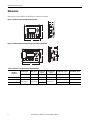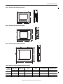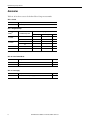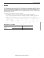
1
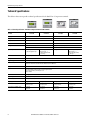
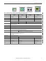
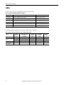
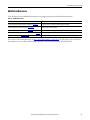
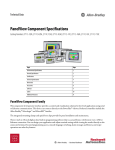
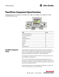
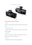
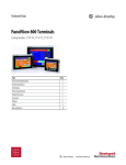
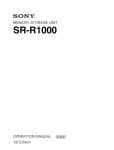
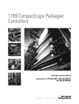
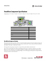
Technical Data
PanelView Component Specifications
Catalog Numbers 2711C-F2M, 2711C-K2M, 2711C-T3M, 2711C-K3M, 2711C-T4T, 2711C-T6M, 2711C-T6T, 2711C-T10C
Topic
Page
Environmental Specifications
2
General Specifications
3
Certifications
3
Technical Specifications
4
Dimensions
6
Accessories
8
Software
9
Cables
10
Additional Resources
11
PanelView Component Family
This component-level operator interface provides a control and visualization solution for low-level applications using serial
or Ethernet communication. This device can connect directly to the PowerFlex® 4 drives. Preferred controllers include the
Allen-Bradley® Micrologix™ and Micro800™ families.
The integrated mounting clamps and quick lever clips provide for panel installation and maintenance.
These 2-inch to 10-inch displays have built-in programming software that is accessed from a web browser over a USB or
Ethernet connection. This means you can design your application and adjust terminal settings while viewing the results
directly on the connected terminal. Secured programming access, unicode language switching, alarm messages and history,
and recipe operations are other key features.
PanelView Component Specifications
Environmental Specifications
Table 1 - Environmental Specifications - PanelView Component Terminals
2
Attribute
2711C-F2M, 2711C-K2M, 2711C-T3M, 2711C-K3M, 2711C-T4T, 2711C-T6M, 2711C-T6T, 2711C-T10C
Temperature, operating
IEC 60068-2-1 (Test Ad, Operating Cold),
IEC 60068-2-2 (Test Bd, Operating Dry Heat),
IEC 60068-2-14 (Test Nb, Operating Thermal Shock):
0…50 °C (32…122 °F)
Temperature, nonoperating
IEC 60068-2-1 (Test Ab, Unpackaged Nonoperating Cold),
IEC 60068-2-2 (Test Bb, Unpackaged Nonoperating Dry Heat),
IEC 60068-2-14 (Test Na, Unpackaged Nonoperating Thermal Shock):
-25…70 °C (-13…158 °F)
Temperature, surrounding, max
50 °C (122 °F)
Heat Dissipation
C200/C300: 16 BTU/hr
C400: 24 BTU/hr
C600: 32 BTU/hr
C1000: 58 BTU/hr
Relative humidity
IEC 60068-2-30 (Test Db, Unpackaged Damp Heat):
5…95% noncondensing
Vibration
IEC 60068-2-6 (Test Fc, Operating):
2 g @ 10…500 Hz
Shock, operating
IEC 60068-2-27 (Test Ea, Unpackaged Shock):
15 g @ 11 ms
Shock, nonoperating
IEC 60068-2-27 (Test Ea, Unpackaged Shock):
30 g
Emissions
CISPR 11:
Group 1, Class A
ESD immunity
IEC 61000-4-2:
4 kV contact discharges
8 kV air discharges
Radiated RF immunity
IEC 61000-4-3:
10V/m with 1 kHz sine-wave 80% AM from 80…2000 MHz
3V/m with 1 kHz sine-wave 80% AM from 1400…2000 MHz
1V/m with 1 kHz sine-wave 80% AM from 2000…2700 MHz
EFT/B immunity
IEC 61000-4-4:
±2 kV @ 5 kHz on power ports
±1 kV @ 5 kHz on communication ports
Surge Transient immunity
IEC 61000-4-5:
±500V line-line (DM) and ±1 kV line-earth (CM) on DC power ports
±1 kV line-earth (CM) on communication ports
Conducted RF immunity
IEC 61000-4-6:
10V rms with 1 kHz sine-wave 80% AM from 150 kHz…80 MHz
Rockwell Automation Publication 2711C-TD001C-EN-P - March 2012
PanelView Component Specifications
General Specifications
Table 2 - General Specifications
Attribute
2711C-F2M, 2711C-K2M, 2711C-T3M, 2711C-K3M, 2711C-T4T, 2711C-T6M, 2711C-T6T, 2711C-T10C
Isolation voltage
For 2711C-T4T only
30V (continuous), Basic Insulation Type
Tested @ 500V for 60 s, line to Ethernet
No isolation between all ports to line, except Ethernet port
Duration indicates that the product was qualification or type tested to the specified level (one time tested on
a representative sample)
Wire size
Single-Wire Gauge: 0.33…2.08 mm2 (22...14 AWG)
Dual-wire Gauge: 0.33…1.31 mm2 (22…16 AWG)
Earth wire: 2.08…3.31 mm2 (14…12 AWG)
Wire type
Solid or stranded copper wire rated @ 90 °C (194 °F ), or greater
Wiring category(1)
1 – on power ports
1 – on communication ports
Enclosure type ratings
Meets NEMA/UL Type 4X (indoor) 12, 13, and IEC IP54, IP65 (when marked)
C600 Series B only: NEMA/UL Type 12, 13, and IEC IP54
North American Temp Code
T3C – for 2711C-T4T only
(1) Use this Conductor Category information for planning conductor routing. Refer to Industrial Automation Wiring and Grounding Guidelines, publication 1770-4.1.
Certifications
Table 3 - Certifications - PanelView Component Terminals
Certification(1)
2711C-F2M, 2711C-K2M, 2711C-T3M, 2711C-K3M, 2711C-T4T, 2711C-T6M, 2711C-T6T, 2711C-T10C
c-UL-us
• UL Listed Industrial Control Equipment, certified for US and Canada. See UL File E113724.
• UL Listed for Class 1, Division 2, Group A, B, C, D, Hazardous Locations, certified for U.S. and Canada. See UL File E10314.
CE
European Union2004/108/EC EMC Directive, compliant with:
• EN 61000-6-2; Industrial Immunity
• EN 61000-6-4; Industrial Emissions
C-Tick
Australian Radiocommunications Act, compliant with:
AS/NZS CISPR 11; Industrial Emissions
KCC
Korean Registration of Broadcasting and Communications Equipment, compliant with:
Article 58-2 of Radio Waves Act, Clause 3
(1) When marked. See the Product Certification link at http://www.ab.com for Declarations of Conformity, Certificates, and other certification details.
Rockwell Automation Publication 2711C-TD001C-EN-P - March 2012
3
PanelView Component Specifications
Technical Specifications
The tables in this section provide technical specifications for the PanelView™ Component terminals.
Table 4 - Technical Specifications - PanelView Component C200 and C300 Terminals
C200
2711C-F2M
Attribute
C200
2711C-K2M
C300
2711C-T3M
C300
2711C-K3M
Display type
Monochrome transflective STN passive matrix
Monochrome transflective FSTN passive matrix
Display size
2 in.
3 in.
Display area (WxH)
49 x 14 mm (1.93 x 0.55 in.)
67 x 33 mm (2.64 x 1.30 in.)
Resolution
122 x 32
128 x 64
Backlight
50,000 hours life, min; not replaceable
50,000 hours life, min; not replaceable
Yellow/Green LED indicator
White LED indicator
Operator input
4 function keys (F1…F4)
Up, down, left, right, Enter keys
Real-time clock
No battery backup
Battery
5 year min at 25 °C (77 °F)
Programming port
USB device port
Communication ports
RS-232 (DH-485), RS-232 (DF1), RS485
Multi-vendor communication available for Modbus, Modbus/TCP, Siemens MPI devices
Memory card
USB flash drive
Software
DesignStation sofware, version 2.0 or later
Web-enabled software resident in terminal accessed through web browser
Browser support: Firefox 3.0, Internet Explorer 7 or 8
Emulator available
Preferred controller
MicroLogix, SLC, and Micro800 controllers
Input voltage, DC
18…30V DC (24V DC nom)
Power consumption, DC
5 W max (0.21 A at 24V DC)
Weight, approx
0.19 g (0.40 lb)
0.30 kg (0.65 lb)
0.20 kg (0.43 lb)
0.30 kg (0.65 lb)
Dimensions (HxWxD), approx
80 x 116 x 54 mm
3.15 x 4.54 x 2.13 in.
119 x 139 x 55 mm
4.69 x 5.47 x 2.15 in.
80 x 116 x 57 mm
3.15 x 4.54 x 2.23 in.
119 x 139 x 55 mm
4.69 x 5.47 x 2.15 in.
Cutout dimensions (HxWxD), approx
65 x 100 mm
2.56 x 3.94 in.
100 x 120 mm
3.94 x 4.72 in.
65 x 100 mm
2.56 x 3.94 in.
100 x 120 mm
3.94 x 4.72 in.
4
10 function keys (F1…F10)
Numeric keypad 0…9
Up, down, left, right, decimal,
+/-, Enter keys
Analog touch
Rockwell Automation Publication 2711C-TD001C-EN-P - March 2012
10 function keys (F1…F10)
Numeric keypad 0…9
Up, down, left, right, decimal,
+/-, Enter keys
PanelView Component Specifications
Table 5 - Technical Specifications - PanelView Component C400, C600, and C1000 Terminals
C400
2711C-T4T
Attribute
C600
2711C-T6T
C600
2711C-T6M
Display type
Color transmissive TFT
active matrix LCD
Color transmissive TFT
active matrix LCD
Display size
4.3 in.
5.7 in.
10.4 in.
Display area (WxH)
95 x 53.86 mm (3.74 x 2.12 in.)
115 x 86 mm (4.53 x 3.39 in.)
211 x 158 mm (8.31 x 6.22 in.)
Resolution
480 x 272
320 x 240
640 x 480
Backlight
40,000 hours life, min; not replaceable
White LED backlight
Analog touch
Actuation rating: 1,000,000 presses
Real-time clock
Battery backup
Color transmissive TFT
active matrix LCD
50,000 hours life, min; not replaceable
White LED backlight
Operator input
Monochrome transmissive FSTN
passive matrix
C1000
2711C-T10C
CCFL
Battery life
5 year min at 25 °C (77 °F)
Programming port
USB device port or Ethernet port
Communication ports
RS-232 (DH-485), RS-232 (DF1), RS485, Ethernet
Multi-vendor communication available for Modbus, Modbus/TCP, Siemens MPI devices
Memory card
USB flash drive
Software
DesignStation sofware, version 2.0 or later
Web-enabled software resident in terminal accessed through web browser
Browser support: Firefox 3.0, Internet Explorer 7 or 8
Emulator available
Preferred controller
MicroLogix, SLC™, and Micro800 controllers
Input voltage, DC
18…30V DC (24V DC nom)
18…30V DC (24V DC nom)
Power consumption, DC
3.5 W max (0.14 A at 24V DC)
10 W max (0.42 A at 24V DC)
18 W max (0.75 A at 24V DC)
Weight, approx
0.35 g (0.76 lb)
0.68 g (1.48 lb)
1.57 kg (3.41 lb)
Dimensions (HxWxD), approx
113 x 138x 43 mm
4.45 x 5.43 x 1.69 in.
154 x 209 x 57 mm
6.0 x 8.23 x 2.25 in.
250 x 308 x 54 mm
9.84 x 12.13 x 2.13 in.
Cutout dimensions (HxWxD),
approx
99 x 119 mm
3.9 x 4.69 in.
136 x 190 mm
5.35 x 7.48 in.
232 x 290 mm
9.13 x 11.42 in.
USB flash drive
Secure Digital (SD) card: Cat. no. 2711C-RCSD, USB to SD adapter with SD card
Rockwell Automation Publication 2711C-TD001C-EN-P - March 2012
5
PanelView Component Specifications
Dimensions
Dimensions are provided for the PanelView Component terminals.
Figure 1 - PanelView Component C200 and C300 Terminals
c
d
a
F1 1
F2 2
F3 3
F4 4
F5 5
F6 6
F7 7
F8 8
F9 9
F10 0
b
Figure 2 - PanelView Component C200 Function Key and C300 Touch Terminals
c
d
a
F1
F2
F3
F4
b
Table 6 - Dimensions - PanelView Component C200 and C300
PanelView
Component
C200 and C300 Keypad
C200 Function Key
C300 Touch
6
Height, approx
Width, approx
Depth Overall,
approx
Mounted Depth,
approx
Cutout Height, approx
Cutout Width, approx
a
b
c
d
mm (in.)
mm (in.)
119 mm (4.69 in.)
139 mm (5.47 in.) 55 mm (2.15 in.)
80 mm (3.15 in.)
116 mm (4.57 in.)
54 mm (2.13 in.)
57 mm (2.23 in.)
49 mm (1.93 in.)
49 mm (1.93 in.)
99.0 ± 1.0 (3.90 ± 0.04)
119.0 ± 1.0 (4.69 ±0.04)
64.0 ± 1.0 (2.52 ± 0.04)
99.0 ± 1.0 (3.90 ±0.04)
64.0 ± 1.0 (2.52 ± 0.04)
99.0 ± 1.0 (3.90 ±0.04)
Rockwell Automation Publication 2711C-TD001C-EN-P - March 2012
PanelView Component Specifications
Figure 3 - PanelView Component C400 Touch Terminal
c
d
a
b
Figure 4 - PanelView Component C600 Touch Terminal
c
d
PanelView C600
a
b
Figure 5 - PanelView Component C1000 Touch Terminal
c
d
PanelView C1000
6
a
6
b
Table 7 - Dimensions - PanelView Component C400, C600, and C1000
PanelView
Component
Height, approx
Width, approx
Depth Overall,
approx
Mounted Depth,
approx
Cutout Height, approx
Cutout Width, approx
a
b
c
d
mm (in.)
mm (in.)
C400 Touch
113 mm (4.45 in.)
138 mm (5.43 in.)
43 mm (1.69 in.)
38 mm (1.49 in.)
99.0 ± 1.0 (3.90 ± 0.04)
119.0 ± 1.0 (4.69 ±0.04)
C600 Touch
154 mm (6.0 in.)
209 mm (8.23 in.)
57 mm (2.25 in.)
49 mm (1.93 in.)
135.0 ± 1.0 (5.31 ± 0.04)
189.0 ± 1.0 (7.44 ±0.04)
C1000 Touch
250 mm (9.84 in.)
308 mm (12.13 in.)
54 mm (2.13 in.)
49 mm (1.93 in.)
231.0 ± 1.0 (9.09 ± 0.04)
289.0 ± 1.0 (11.38 ±0.04)
Rockwell Automation Publication 2711C-TD001C-EN-P - March 2012
7
PanelView Component Specifications
Accessories
Tables 8…11 list the accessories for the PanelView Component terminals.
Table 8 - SD Card
Cat. No.
Description
2711C-RCSD
USB to SD adapter with SD card
Table 9 - Antiglare Overlays
Cat. No.(1)
Input Type
PanelView Component
Function Key
C200
2711C-RG2F
Numeric Keypad
Touch
•
C300
2711C-RG2K
•
C200
•
C300
•
2711C-RG6T
C600
•
2711C-RG10T
C1000
•
(1) Three overlays are shipped with each catalog number.
Table 10 - Power Terminal Blocks
Cat. No.
Description
Quantity
2711C-RJ422
RS422/485 connector with resistor
10
2711-TBDC
DC power terminal block
10
Table 11 - Power Supply
8
Cat. No.
Description
Quantity
2711P-RSACDIN
DIN-rail mount AC-to-DC power supply, 85…265V AC, 47…63 Hz
1
Rockwell Automation Publication 2711C-TD001C-EN-P - March 2012
PanelView Component Specifications
Software
The PanelView Component stands apart from other HMI devices with its on-terminal programming software. Eliminating
the need to install software on a personal computer reduces both start-up and servicing time. Just connect your computer to
the PanelView Component through a USB cable or Ethernet, then launch the software through your web browser. Both
Microsoft Internet Explorer and Mozilla Firefox are supported. A dashboard provides a single point of entry for accessing
all terminal and design operations.
Take advantage of these features while connected to the terminal:
• Launch the design environment where navigation tabs guide you through application development.
• View the results of your design efforts directly on the terminal without having to download the application first.
• Modify terminal display and communication settings, view system information, and enable login security.
• Transfer files between PanelView Component storage and a USB flash drive, SD card, or computer; and delete files
from terminal storage.
• Change the start-up application or language the terminal uses for configuration screens and diagnostic messages.
For programming without a PanelView Component, you can create an application using the free DesignStation software or
an emulator. The emulator and browser must be on the same computer.
Table 12 - Supported Browsers and Platforms
Operating System
Browser
Platform Supported
Windows 7
Windows Vista
Windows XP SP2
Internet Explorer 7 and 8, Firefox 3.0
Terminal and emulator
Internet Explorer 7 and 8
DesignStation 2.0 or later
Rockwell Automation Publication 2711C-TD001C-EN-P - March 2012
9
PanelView Component Specifications
Cables
Use these cables for connecting PanelView Component terminals.
Table 13 - Cables for PanelView Component Terminals
Cat. No.
Description
For Use With
2711C-CBL-UU02
USB-A host to USB-B device cable, 2 m (6.5 ft)
C200, C300, C400, C600, C1000
2711P-CBL-EX04
Ethernet crossover CAT5 cable, 4.3 m (14 ft)
C400, C600, C100
2711C-RCSD
USB to SD adapter with SD card
C200, C300, C400, C600, C1000
1747-CP3
Serial 9-pin D-shell to 9-pin D-shell null modem cable, 3 m (10 ft)
C200, C300, C400, C600, C1000
1761-CBL-PM02
Serial 9-pin D-shell to 8-pin mini DIN cable, 2 m (6.5 ft)
C200, C300, C400, C600, C1000
2711C-CBL-AB03
RS-485 5-pin to RJ45 cable
C200, C300, C600, C1000
This table provides a summary of connections to MicroLogix controllers.
Table 14 - PanelView Component Terminal Connections to MicroLogix Controllers
Protocol
DF1
DH-485
PanelView
Component Port
MicroLogix (8-pin Mini DIN)
1000, 1100, 1400, 1200LSP,
1500LSP (CH0)
MicroLogix
(9-pin D-shell)
1500LRP (CH1)
MicroLogix
1100/1400 RS485
(1763-NC01)
MicroLogix
1100, 1400
Ethernet
RS-232
1761-CBL-PM002
1747-CP3
1747-CP3
—
RS-232
1761-CBL-PM002
1747-CP3
1747-CP3
—
RS-485(1)
—
—
—
—
Modbus
RS-232
1761-CBL-PM002
1747-CP3
1747-CP3
—
EtherNet
(MicroLogix/ENI)2
Ethernet
—
—
—
CAT5 Ethernet
(1) RS-485 is nonisolated and is recommended for connecting to only one device with an isolated port.
10
Rockwell Automation Publication 2711C-TD001C-EN-P - March 2012
PanelView Component Specifications
Additional Resources
These documents contain additional information concerning related products from Rockwell Automation.
Table 15 - Additional Resources
Resource
Description
PanelView Component Installation Instructions, publication 2711C-IN001
Provides instructions for installing a PanelView Component terminal.
PanelView Component User Manual, publication 2711C-UM001
Provides information on how to configure and operate the PanelView Component terminal,
including troubleshooting information.
PanelView Component Quick Start, publication 2711C-QS001
Provides instructions on setting up a sample application on a PanelView Component terminal.
Industrial Automation Wiring and Grounding Guidelines, publication 1770-4.1
Provides general guidelines for installing a Rockwell Automation industrial system.
Product Certifications website, http://www.ab.com
Provides declarations of conformity, certificates, and other certification details.
You can view or download publications at http://rockwellautomation.com/literature. To order paper copies of technical
documentation, contact your local Allen-Bradley distributor or Rockwell Automation® sales representative
Rockwell Automation Publication 2711C-TD001C-EN-P - March 2012
11
Important User Information
Solid-state equipment has operational characteristics differing from those of electromechanical equipment. Safety
Guidelines for the Application, Installation and Maintenance of Solid State Controls (publication SGI-1.1 available from
your local Rockwell Automation sales office or online at http://www.rockwellautomation.com/literature/) describes some
important differences between solid-state equipment and hard-wired electromechanical devices. Because of this difference,
and also because of the wide variety of uses for solid-state equipment, all persons responsible for applying this equipment
must satisfy themselves that each intended application of this equipment is acceptable.
In no event will Rockwell Automation, Inc. be responsible or liable for indirect or consequential damages resulting from the
use or application of this equipment.
The examples and diagrams in this publication are included solely for illustrative purposes. Because of the many variables
and requirements associated with any particular installation, Rockwell Automation, Inc. cannot assume responsibility or
liability for actual use based on the examples and diagrams.
No patent liability is assumed by Rockwell Automation, Inc. with respect to use of information, circuits, equipment, or
software described in this manual.
Reproduction of the contents of this manual, in whole or in part, without written permission of Rockwell Automation,
Inc., is prohibited.
Documentation Feedback
Your comments will help us serve your documentation needs better. If you have any suggestions on how to improve this
document, complete this form, publication RA-DU002, available at http://www.rockwellautomation.com/literature/.
Allen-Bradley, MicroLogix, SLC, PowerFlex, Micro800, PanelView, Rockwell Software, Rockwell Automation, and LISTEN. THINK. SOLVE are trademarks of Rockwell Automation, Inc.
Trademarks not belonging to Rockwell Automation are property of their respective companies.
Publication 2711C-TD001C-EN-P - March 2012
Supersedes Publication 2711C-TD001B-EN-P - August 2011
Copyright © 2012 Rockwell Automation, Inc. All rights reserved. Printed in the U.S.A.