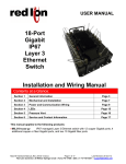
1
Z Microsystems | GCS Display User Manual
GCS DISPLAYS USER MANUAL
Rugged Low-Profile Ground Control Station (GCS) Displays
Installation, Setup, Operations, Maintenance, & Troubleshooting
User Manual
27-0043UM Revision D
Released 01/04/2013
MISSION-READY
RUGGED DEPLOYABLE COMPUTING
Z Microsystems, Inc. · 9820 Summers Ridge Road, San Diego, CA 92121 · T: 858.831.7000 · F: 858.831.7001 · www.zmicro.com
REGULATORY
Z Microsystems | GCS Display User Manual
REGULATORY INFORMATION
WARNING
TO PREVENT FIRE OR SHOCK HAZARDS, DO NOT EXPOSE THIS UNIT TO RAIN OR MOISTURE. ALSO, DO NOT USE THIS UNIT’S POLARIZED
AC PLUG WITH AN EXTENSION CORD RECEPTACLE OR OTHER OUTLETS UNLESS ALL THREE PRONGS CAN BE FULLY INSERTED
CAUTION
RISK OF ELECTRIC SHOCK - DO NOT OPEN
CAUTION: TO REDUCE THE RISK OF ELECTRIC SHOCK DO NOT REMOVE COVER (OR BACK OF UNIT). NO USER SERVICEABLE PARTS
INSIDE. REFER SERVICING TO QUALIFIED PERSONNEL.
This symbol warns the user that insulated voltage within the unit may have sufficient magnitude
to cause electric shock. Therefore, it is dangerous to make any kind of contact with any part
inside this unit.
This symbol alerts the user that important literature concerning the operation and maintenance
of this unit has been included. Therefore it should be read carefully in order to avoid any
problems.
1. Use the power and video cables supplied with the product to help prevent interference with radio and television reception.
adapters may cause interference with electronic equipment in the vicinity of this unit.
The use of cables and
2. This equipment has been designed to meet severe conditions in military environments as specified in MIL-STD-810G, MIL-STD-461F and DO-160F.
3. This equipment is designed to meet the limits for Class A digital devices imposed by Part 15 of FCC rules. These limits are designed to provide
reasonable protection against harmful interference when equipment is operating in commercial environments. This equipment generates, uses and
can radiate radio frequency energy, and, if not installed and used in accordance with the instruction manual, may cause harmful interference to radio
communications.
4. Operation of this equipment in a residential area is likely to cause interference in which case the user will be required to correct the interference at his
own expense. Changes or modifications not expressly approved by Z Microsystems could void user’s authority to operate the equipment.
ii
TABLE OF CONTENTS
Z Microsystems | GCS Display User Manual
TABLE OF CONTENTS
Section
Page
1.0 Product Overview...............................................................................................................................................................1
1.1 About This Manual.................................................................................................................................................1
1.2 Product Description...............................................................................................................................................2
2.0 Installation..........................................................................................................................................................................3
2.1 GCS Array Installation............................................................................................................................................3
2.2 Viewing Angle Adjustments on Top Wing Display...................................................................................................5
.
3.0 Connections & Setup..........................................................................................................................................................6
3.1 GCS Display Connections Process........................................................................................................................6
3.2 Touch Panel Setup................................................................................................................................................7
3.3 Touch Panel Operation........................................................................................................................................10
.
4.0 Operations .......................................................................................................................................................................11
4.1 Front Panel Button & LED Controls......................................................................................................................11
4.2 On-Screen Display Menus...................................................................................................................................12
4.2.1 Main Menu..........................................................................................................................................12
4.2.2 Picture Adjust.....................................................................................................................................12
4.2.3 Graphics Mode...................................................................................................................................12
4.2.4 Color Balance.....................................................................................................................................13
4.2.5 Configuration......................................................................................................................................13
4.2.6 Advanced Options..............................................................................................................................13
4.2.7 Information..........................................................................................................................................15
4.3 Preparing the GCS Array for Transport.................................................................................................................16
.
5.0 Maintenance ....................................................................................................................................................................18
5.1 Routine Maintenance and Cleaning......................................................................................................................18
6.0 Troubleshooting the GCS Series.......................................................................................................................................19
6.1 Troubleshooting Topics........................................................................................................................................19
6.2 Frequently Asked Questions................................................................................................................................21
.
7.0 Customer Support............................................................................................................................................................22
7.1 Contact Information.............................................................................................................................................22
7.2 Parts Replacement..............................................................................................................................................23
8.0 Appendix..........................................................................................................................................................................24
8.1 GCS 17” - Technical & Environmental Specifications............................................................................................24
8.2 GCS 21” - Technical & Environmental Specifications............................................................................................26
8.3 GCS 24” - Technical & Environmental Specifications............................................................................................28
.
iii
Z Microsystems | GCS Display User Manual
1.0 PRODUCT OVERVIEW
This section will provide information and assistance with the following topics:
• About This Manual
SAFETY PRECAUTIONS
• Product Overview
DANGER: To avoid shock hazard:
1.1 ABOUT THIS MANUAL
• Do not remove the covers around
the GCS Display.
This product manual provides information about the features, installation,
connections, operation, troubleshooting, product replacement, limited
warranty, and other important details about your new Z Microsystems product.
We recommend that you read this manual carefully and follow the instructions
in the installation chapter for verification of system functions and settings.
• Do not connect or disconnect the
GCS Display during an electrical
storm.
This product manual and other resources are also available on the Z
Microsystems website at www.zmicro.com. For further assistance please visit
the Troubleshooting & Frequently Asked Questions section within this manual,
or refer to the section dedicated to Customer Support.
• The power cord plug must be
connected to a properly wired and
grounded power outlet.
For added convenience and safety, you will find bookmarks and embedded
visual cues for quick tips, warnings, new sections, and other safety related
precautions. These are intended for quick supplemental reference and added
ease in the installation process and during operations of the GCS Display.
Visual Notifications:
WARNINGS AND SAFETY PRECAUTIONS
NOTES AND PREPARATIONS
Necessary Tools
Necessary Hardware
Cabling & Connections
Necessary Drivers/Software
Additional assistance reference information, and configuration options for the GCS Display
Series and other Z Microsystems’s product can be found online at www.zmicro.com.
1
Z Microsystems | GCS Display User Manual
1.2 PRODUCT DESCRIPTION
Z Microsystems’s Ground Control Station (GCS) Display Series delivers a robust visual solution withadvanced
mobility, quick-lock features, and low-profile performance for command station and visual array applications.
The GCS display is engineered with a custom quick-lock mounting configuration, ultra-high performance
modular video processor, and touch panel options. Manufactured from lightweight CNC-machined aircraftgrade aluminum, the GCS is a thin, lightweight, and rugged solution for high definition performance in 17”,
21”, and 24” sizes.
With the powerful 3rd generation Z Microsystems video processor, the GCS Series offers advanced Real
Time Enhanced Video (RTEV ) capabilities to improve tactical surveillance missions. These real-time image
improving functions process enhancements including: de-blurring, de-hazing, de-fogging, edge detection
and other algorithms for improved image quality, without adding latency to the incoming video stream. This
technology delivers high-definiton surveillance imaging in real-time without quality degradation caused by
poor visibility or atmospheric interference.
These displays also offer interactive touch screen functionality for intuitive accessibility to live imagery and
intelligence. The GCS Series Displays offer increased user-effectivity and information distribution for mobility
in Command Station deployment and operations.
Highlights
•
•
•
•
•
•
•
17”, 21”, & 24” active display area
Native Pixel Resolutions up to
1920 x 1200@60 pixels for 24”
1600 x 1200@60 pixels for 21”
1280 x 1024@60 pixels for 17”
Supported scaled resolutions up to
1920x1200@60 for 17”, 21”, and 24”
Digital and analog video support
RS232 Communications via USB Type B
connector
Real-time enhanced video imaging
Soft Menu user-friendly on-screen GUIs
•
•
•
•
•
•
•
•
Tough protective AR shield
Standard optically bonded AR shield
Optional optically bonded touch panel
Rugged lightweight packaging
Custom mounting options (Vesa Standard)
Optional quick-release mounting
Viewing angles are fully adjustable per
5th - 95th percentile MIL-STD ergonomics
specifications
Applications include shipboard,
airborne, ground vehicles, & ground control
stations
2
Z Microsystems | GCS Display User Manual
PREPARATIONS
SETUP NOTES
In preparation to setting up and
installing the GCS Display, turn off
the electrical power to computers
and other electronic devices that will
connect to the unit.
For fastest and easiest installation of
the GCS Display Series, follow these
instructions or the Installation Guide
provided with your shipment.
WARNING
Using assembly hardware that
does not match the provided
specifications may damage internal
components.
2.0 INSTALLATION
This section will provide information and assistance with the following topics:
• Shipment Contents
• Mounting Hardware
• Installation Walkthrough
• Ground Control Station Platform Adjustments
2.1 GCS ARRAY INSTALLATION
Shipment Contents
Before continuing with installation, please verify that all contents have been received and are in working condition. If any of
the parts are missing or damaged, please contact Z Microsystems’s at:
Customer Service T: 858-831-7040
REQUIRED TOOLS
DESCRIPTION
3/32” Allen Key
For adjustments of friction hinges
#2 Phillips Screwdriver
For attaching filler panel & other adjustments throughout installation
1. Attach the filler panel at the top of the
mounting rack using a Philips screwdriver.
2. Extend slides from mounting rack.
3. With the aid of a second person for
assistance, lift the chassis frame assembly
onto the slide rails. There will be an audible
“click” when the slides are inserted into the
rails when secure.
3
Z Microsystems | GCS Display User Manual
4. When Chassis is secure, extend the unit out
for easy access to rear connectors and IO
panel.
5. Attach the corresponding cables to the rear
side of the System I/O panel.
6. To mount a display, open the quick release
latch on the rear of the Chassis display frame.
7. Lift and hold the display to the frame
and align the display’s pins with the
corresponding holes in the display frame.
8. When all display alignment pins have been
aligned, hold the display firmly against the
frame, and close the quick release latch on
the rear.
9. Repeat the steps to attach all the display to
the corresponding frames.
10. If necessary, unfasten the lock down cable
bracket to adjust cable length.
11. Plug in all relevant cables into rear underside
of displays.
4
Z Microsystems | GCS Display User Manual
2.2 Viewing Angle Adjustments on Top Wing Display
1. Loosen the hinge slack mechanism in the
rear of the GCS 17 inch display frame.
2. Once the display is free to adjust, use your hands to position the GCS 17 inch display
unit at the desired angle.
4. Retighten the hinge slack mechanism in the
rear of the GCS 17 inch display frame to lock
position of the display.
5. To adjust any of the display’s friction hinges,
use an Allen key to evenly loosen or tighten
the locking hinge mechanism to suite desired
resistance.
3. When extreme viewing angles are
required, slide the GCS 17 forward to clear
interference with the top display.
5
Z Microsystems | GCS Display User Manual
3.0 CONNECTIONS & SETUP
PREPARATIONS
This section will provide information and assistance with the following topics:
• Required cable connections
• Touch panel setup and operation
• Touch panel operation drivers
In preparation to setting up and
installing the GCS Display, turn off
the electrical power to computers
and other electronic devices that will
connect to the unit.
3.1 GCS Display Connections Process
Host
DVI-I 1
DVI-I 2
Power In
GCS INPUT
INPUT DESCRIPTION
CONNECTION CABLE
USB Host
USB Type B Input
USB Type B-A host communication cable
DVI-I 1
DVI-I (Dual-Link) Video Input
Video input for Channel 1 (supports digital & analog)
DVI-I 2
DVI-I (Dual-Link) Video Input
Video input for Channel 2 (supports digital & analog)
Power In
C14 IEC 320 socket
C13 IEC 320 to NEMA 5-15P power connector
1. Once the GCS display has been installed,
connect the IEC power cable to the Power In
input.
2. There are two available video inputs, labelled
DVI-I 1 and DVI-I 2 for Channels 1 and 2,
respectively. Connect the DVI-I (or DVI-D digital only) cable as needed for video signals
provided to the GCS display.
3. If the touchscreen option has been
purchased for the display, or if GUI menu
support is in use, ensure that the USB host
cable is securely connected throughout
operation.
(If your GCS features another video input type, use the appropriate connector and cable)
6
Z Microsystems | GCS Display User Manual
PREPARATIONS
SETUP TIP
INFRARED TOUCH
In preparation to connecting GCS
displays, turn off the electrical power
to computers and other electronic
devices that will connect to the unit.
If the display is connected to power and
video but does not recognize a video
signal, the user will be notified with a
message stating, “NO SYNC, PLEASE
CHECK CABLE.”
For operation of the infrared touch
screen with the GCS display, no drivers
are necessary.
3.2 TOUCH PANEL SETUP
Most modern Operating Systems have
the Human Interface Display (HID)
drivers built into them. The infrared
touch screen should be automatically
recognized.
Required Software & Drivers
• FTDI RS232-USB Bridge Driver
• Microchip TSHARC Touch Panel Driver
The GCS Series Displays feature an optional resistive touch panel for intuitive touch function operations. This 5-wire resistive touch screen array will recognize
the touch of a finger, gloved finger, stylus, pen, or other implement.
FTDI & Microchip drivers for this resistive touch screen will be required. Resistive touch drivers and utilities for other products can be found on the Product
DVD that was included in your shipment or online at our website:
www.zmicro.com/downloads/drivers.html
www.ftdichip.com/Drivers/VCP.htm
www.microchip.com/stellent/idcplg?IdcService=SS_GET_PAGE&nodeId=2830
Resistive Touch Panel Setup Steps
DRIVERS ON THE SITE
Please ensure that the USB host communication cable is securely connected to the display.
Step 1 - Download and Install RS232 over USB drivers
Z Microsystem’s touch panel driver communicates to a host computer via a RS232 over USB bridge.
In order to communicate with the touch panel, you must first install the FTDI RS232-USB bridge driver
from the following link:
Once installed, the driver will assign two Virtual Communication Ports (VCP) when the display is connected to the host computer via the USB Type B cable. The first VCP will be utilized for serial communication to the display controller. The second VCP is assigned to touch panel control.
Step 2 - Download and Install Microchip TSHARC Touch Panel driver
Once the RS232 over USB drivers are installed, you will need to download the Microchip TSHARC
touch panel drivers from the link provided above.
Select the driver for your specific operating system found within the driver table. (i.e. Windows, Linux,
Mac)
Touch screen drivers and utilities for
other products can be found at www.
zmicro.com:
1. Access the “Resources” submenu from
the Header Menu.
2. Select the “Downloads & Drivers” option.
3. Navigate to the desired product type.
FOR WINDOWS
We recommend Microsoft Windows
users select the Setup.exe labelled for
Win7/Vista/WinXP driver.
(It is also distinguished as a “third party
driver” under the “Notes” column.)
7
Z Microsystems | GCS Display User Manual
Step 3 - Install and Setting the TSHARC Touch Panel Driver COM port
Select Microchip, TSHARC-X/X, Serial Option and the respective Port COM setting. Once complete, Click on the Install button.
Upon successful installation of driver, reboot computer if necessary. If the touch panel is not responding, open the ‘Universal Pointer Device Driver (UPDD)’
Control Panel and update the COM port setting. Indicate which Port number your touch panel is connected to and test again.
COM PORT NOTE
If the touch panel is not responding, you
may need to open the ‘Universal Pointer
Device Driver (UPDD)’ Control Panel and
update the COM port setting.
Step 3: TSHARC Install
Step 4 - Configuring the TSHARC Touch Panel driver
For basic Touch Panel operation, proceed to the ‘Universal Pointer Device Driver (UPDD)’ Control Panel. The UPDD control panel allows the user to set calibration and other touch panel device properties. Complete the following steps for key setup and calibration requirements:
To use the Touch Panel with Click and Drag settings - Select “Click Mode” tab from the menu on the left, then verify the hardware is configured to Click and
Drag in the pull down menu.
Step 5 - Calibration of the Touch Screen Controller
Select the “Calibrate” tab and follow the on-screen guide to ensure the touch screen controller is properly calibrated for your display. Calibration window is
illustrated below.
CALIBRATION NOTE
If the touch panel is not responding
accurately, the panel may need to
be calibrated through a calibration
resource specific to your operating
system. This is in addition to the
Microchip Touch Screen Controller
Calibration Tool pictured here.
Step 5: Touch Screen Calibration
8
Z Microsystems | GCS Display User Manual
STEP 6 (Optional)- Continuous Touch Panel Sensing
Some users may desire continuous touch panel sensing for specific applications or software. This requires the adjustment of lift-off packets within the UPDD
Control Panel. The Default settings for the UPDD driver are set to use lift-off packets that prevent sustained press and sensing. If the desired functionality of
the touch panels requires continuous sensing of touch, follow these steps: (pictured below)
1) Click on the Properties tab on the far left side of the control panel
2) Select the liftoff time option and set the time value to ‘0’
3) OR ensure that the ‘Use lift-off packet’ option is unchecked.
Continuous Touch: Liftoff Time/ Lift-off Packets
Congratulations! Your touch resistive display is now connected, calibrated, and ready for operation!
Additional Setup Assistance
For additional setup support and assistance with touch screen functionality, connectivity, calibration, or other technical issues please refer to the Troubleshooting and FAQ sections located in this manual. Customer Service can also be reached at:
Customer Service Department T: (858) 831-7040 F: (858) 831-7001
Email: [email protected]
Additional Product Support
For additional information on the GCS Display Series or other Z Microsystems’s touch resistive display panels and features, visit the Z Microsystems on the
web at www.zmicro.com, or contact your Z Microsystems sales representative.
9
Z Microsystems | GCS Display User Manual
3.3 TOUCH PANEL OPERATION
Operating the touch panel requires ongoing communication via the USB host communication.
Ensure that the USB communication cable is securely connected to the GCS Series Display and to your host computer throughout operation. When this
communication path has been verified, and all necessary drivers have been installed, the display is ready for touch operation.
Tap to Select - Tap once to select an
application or file. (This is standard to most
operating systems)
Double-Tap to Enter - Double-tapping on an
icon will activate/open the file or icon.
Press and Hold - Pressing and holding for a
few seconds will behave as ‘right-clicking’ on
the item, displaying an action list.
Press and Drag - Pressing and dragging will
allow the user to move the icon, file, or or
object across the screen for the duration of
the hold.
10
Z Microsystems | GCS Display User Manual
4.0 OPERATIONS
NOTE
This section will provide information and assistance with the following topics:
Front panel buttons allow the
user to change settings, control
backlight operations, or revert to
factory settings.
• Display Panel Button Control Functions
• Display Panel LED Functions
• Navigating & changing settings in On Screen Display (OSD)
4.1 FRONT PANEL BUTTON AND LED CONTROLS
The GCS features push-button controls on the lower front bezel of the monitor casing. These buttons provide easy access to the On-Screen Display
(OSD) allowing the user to navigate and adjust image settings. To setup the display, use the following controls to fine tune the image on the screen:
Input
Menu/Select
+
-
Channel 1 & 2
LED Indicators
Exit
Standby
Status
LED Indicator
Front Panel Button Operations
Display Key
Function
Input Select
Toggles between
available channels
with active incoming
signal. Corresponds
with illuminated
Channel LEDs.
Notes
Menu/Select
Activates On-Screen
Display. Activates/
Deactivates selected
menu item.
Moves to previous
menu item.
Decreases value of
the selected menu
item.
+
Moves to next menu
item. Increases the
value of the selected
menu item.
Note: Changes are
saved as they are
modified
Exit
Standby
Exits from OSD,
main menu,
or current
submenu.
Hold down to
illuminate the
backlight.
Note: Changes
are saved as they
are modified
Note: Power
saving option.
This is NOT a
power OFF.
Front Panel LED Operations
Channel LEDs (Channel 1 & 2)
Solid Green
Respective input channel selected
Solid Amber
Error - no signal recognized
Status LED
Solid Green
Display is receiving power and has recognized an incoming signal.
Solid Amber
Display is receiving power but cannot recognize an incoming signal.
Off
Alarm
11
OPERATIONS
Z Microsystems | GCS Display User Manual
4.2 ON-SCREEN DISPLAY MENUS
4.2.1 Main Menu
MAIN MENU
To access the On-Screen Display main menu, press the MENU button on the front panel. All display
R. 52
PICTURE ADJUST
functions are controlled using this Main Menu.
Submenus can be accessed for adjustments and information via the (+) and (-) buttons.
GRAPHIC MODE
COLOR BAL ANCE
Using the (+) and (-) front panel buttons, highlight the desired submenu topic. Press the MENU/
CONFIGURATION
SELECT button to open the submenu topic.
INFORMATION
ADVANCED OPTIONS
Refer to each of the following sections for specific submenu operations.
NOTE: When a submenu slider is selected, the color of the slider will change.
4.2.2 Picture Adjust
PICTURE ADJUST
MAIN
MAIN CONTRAST
(-) buttons, highlight “Picture Adjust” and press MENU/SELECT.
Navigate to the desired option using the (+) and (-) buttons. Press MENU to activate. Use the (+) and
CH 1
MAIN BRIGHTNESS
The Picture Adjust submenu allows adjustment of display brightness and contrast. Using the (+) and
0
100
(-) buttons to increase or decrease the value, respectively. Press MENU or EXIT to deactivate the
0
100
option. Changes will save automatically.
4.2.3 Graphics Mode
The Graphics Mode submenu allows adjustment of the vertical and horizontal positioning of the
GRAPHICS MODE
MAIN
Highlight the desired option using the (+) and (-) buttons. Press MENU to activate the option.
CH 1
HORIZ. COARSE
HORIZ. FINE
VERT. POSITION
HORIZ. POSITION
image. To make changes, highlight “Graphics Mode” from the Main Menu and press MENU.
0
100
0
100
0
100
0
100
(Background color of the slider will change.)
Use (+) and (-) to increase and decrease the value of the selected option, respectively. When finished
with adjustments press MENU or EXIT, to deactivate the option.
Press EXIT to return to the Main Menu. Adjustments will be applied and saved automatically.
12
Z Microsystems | GCS Display User Manual
4.2.4 Color Balance
COLOR BALANCE
The Color Balance submenu allows adjustment of the Red, Green, and Blue Gains of the display.
Highlight “Color Balance” using the (+) and (-) buttons and press MENU.
MAIN
CH 1
RED
GREEN
BLUE
0
100
0
100
0
100
Highlight the desired color gain using the (+) and (-) buttons. Press MENU to activate the option.
(Background color of the slider will change.) Use (+) and (-) to increase and decrease the value of the
selected option, respectively. When finished with adjustments press MENU or EXIT, to deactivate
the option.
Press EXIT to return to the Main Menu. Adjustments will be applied and saved automatically.
NOTE: Color Balance menu topics: Red, Green, and Blue adjustments are only available for analog
signal images. These topics will be unavailable and greyed out when a digital signal is recognized.
4.2.5 Configuration
Menu Timeout:
CONFIGURATION
MAIN
MENU TIMEOUT
Menu Timeout is the duration that menu windows will remain displayed before timing out and
disappearing from the screen. Timeout varies from (0) 4-5 seconds to (99) 4 minutes. With a
0
100
fACTORY SETTINGS
CHANNEL 1 T YPE:
ANALOG
CHANNEL 2 T YPE:
ANALOG
CHANNEL SELECT:
CHANNEL 2
SCALE MODE:
NORMAL
maximum setting of 100, the menu will not timeout until the user toggles the menu off manually.
Reset Default Settings:
Resets all Main Menu settings to the factory defaults.
Scale Mode: Normal, Scaled Aspect Ratio (SAR), or No Scale.
Normal mode scales source image to full panel size and aspect ratio.
SAR mode maintains aspect ratio and scales source image to maximum possible size.
No Scale Mode maintains the native source resolution and aspect ratio of the image.
SAR and No Scale modes center the image on the panel with vertical black bars along the sides
where no image is present.
4.2.6 Advanced Options
ADVANCED OPTIONS
MAIN
RTEV SETTINGS
RTEV GEOMETRY
OSD OPTIONS
These options are available for operation and the future development of Z Microsystems’ Real-Time
Enhanced Video proprietary video enhancement technology.
RTEV Settings:
Adjustment for status, window mode, profile, clarity level, and kernel size.
RTEV Geometry:
Window dimensions: window left, window right, window top, window bottom.
OSD Options:
Vertical position, horizontal position, and transparency of the OSD menu window.
13
Z Microsystems | GCS Display User Manual
RTEV Settings
“RTEV Settings” allows you to modify the status, window mode, profile, clarity level, and kernel size of
the RTEV enhancement functions.
RTEV SETTINGS
MAIN
STATUS
ENABLE
WINDOW MODE
SPLIT MODE
PROFILE
MODERATE
CLARITY LEVEL
KERNEL SIZE
Status:
Enable or disable the RTEV enhancement function. (ON/OFF)
0
100
100
0
10
25
Window Mode:
Toggle between enhancement function window modes: Split Mode, Window Mode, Full Mode. This is
used to define the area of enhancement for the RTEV algorithm
Profile:
Toggle between RTEV enhancement Profiles: Moderate, Fog, Dark, Medical, Max, and Mild. Select
the profile that generates best results depending on the nature of source image.
Clarity Level:
Toggle between enhancement function window modes: Split Mode, Window Mode, Full Mode. Clarity
needs depend on source image. A higher Clarity setting normally brings out more detail.
Kernel Size:
Toggle between enhancement function window modes: Split Mode, Window Mode, Full Mode.
This will vary depending on the source image. In general, smaller kernel sizes produce smoother
enhancement. In order to bring out more details select a small size kernel.
RTEV Geometry
“RTEV Geometry” provides adjustments for the enhancement window found in the “RTEV Settings”
menu. This is the only enhancement mode that these adjustments act upon.
RTEV GEOMETRY
MAIN
WINDOW LEFT
WINDOW RIGHT
WINDOW TOP
WINDOW BOTTOM
0
025
100
0
065
100
0
019
100
0
074
100
Window Left:
Values range from 0-100. This is used to identify current left vertical position of the RTEV window.
Window Right:
Values range from 0-100. Used to identify the current right vertical position of the RTEV window.
Window Top:
Values range from 0-100. Used to identify the current top horizontal position of the RTEV window.
Window Bottom:
Values range from 0-100. Used to identify the current bottom horizontal position of the RTEV window.
OSD Options
“OSD Options” allows you to modify OSD menu settings to adjust the vertical and horizontal position
as well as the transparency of the On-Screen Display.
OSD OPTIONS
MAIN
VERT POSITION
HORIZ POSITION
0
100
0
100
Vert Position:
Vert Position allows the user to change the position of the OSD screen in vertical position (Y-axis).
Horiz Position:
Horiz Position allows the user to change the position of the OSD screen in horizontal position (X-axis).
14
Z Microsystems | GCS Display User Manual
4.2.7 Information
Use the (+) and (-) button to highlight the “Information” option. Press the MENU button to access the
“Information” submenu.
Within this submenu, the user can view firmware version, build date, incoming video signals, and
display operating temperature.
Temperature displayed is the onboard circuit-board temperature. Temperature variation is common
and expected.
WARNING
It is advised to contact Z
Microsystems Customer Support if
the temperature exceeds 65C.
15
Z Microsystems | GCS Display User Manual
4.3 PREPARING THE GCS ARRAY FOR TRANSPORT
Pilot and Sensor Displays Transport Mode
This series of steps will prepare the GCS multi-panel array for transportation. Whenever transporting the
Ground Control Station array it is recommended to follow these steps and secure all monitors and hardware
for safe relocation.
When preparation steps have been completed and all hardware and electronics are secured for
transportation, the GCS is ready for transport. An example image of a properly prepared GCS in
transportation mode is provided at the end of this section for reference.
1. Loosen Top display hold-down captive
fastener from its storage position.
2. Rotate top display to full vertical position
to align display frame with the lock down
mechanism.
3. When the display is aligned with the captive
fastener, screw captive fastener into display
frame to secure display in transport mode.
1. Release the angle lock mechanism on the
rear of the top-wing display.
2. When unlocked, carefully fold the display to
the full down position so that it hangs in front
of the exterior lower display.
3. Release the locking mechanism from the side
of the left wing display and screw the captive
fastener into the hole on the side of the
folded top wing display
4. Carefully rotate the left and right bottom
wing displays towards each other so that
the edges closest to you almost touch each
other.
5. From the underside of the left wing
display, loosen the captive fasteners to
release the sliding locking arm.
6. Slide the locking arm out and fasten the
captive fastener to the hole in the underside
of the opposite display as shown.
16
Z Microsystems | GCS Display User Manual
Transport Mode Setup (Continued)
Example: When finished, the system should look as shown above.
Common View Displays Transport Mode Setup
1. To secure the center common view display,
rotate the display to the vertical position.
2. To lock the display in the vertical position,
turn the knurled nut on the left and right
hinge arm to extends the locking pins.
Continue until the pin is fully extended
through both the hinge arm and the display
frame.
17
Z Microsystems | GCS Display User Manual
5.0 MAINTENANCE
5.1 ROUTINE MAINTENANCE AND CLEANING
Unplug the monitor from the power outlet before cleaning.
• GCS rugged displays are engineered for operation in extreme conditionsutions,
but don’t treat them that way if you can help it.
• These displays are constructed with one of the following optical bonds: a
resistive touchscreen, infrared touchscreen, an Anti-Reflective (AR) shield, or
an Anti-Glare (AG) shield. The optically bonded LCD panels of the GCS display
can be damaged if not treated properly during routine maintenance and
cleaning.
WARNING
TO AVOID THE RISK OF
ELECTRICAL SHOCK
DO NOT disassemble the monitor
cabinet. Users cannot service
the monitor. User maintenance is
restricted to cleaning as explained
below.
TURN OFF and remove power to
the display before performing any
maintenance to the display.
• When cleaning the surface of the screen, always use a clean lint-free cloth.
Isopropyl alcohol or glass cleaner specifically designed for LCD displays is
recommended. Use one of these to remove finger prints, smudges, and other
debris from the monitor screen.
Cleaning Directions
1) Apply approved cleaning solution to the clean, lint-free cloth.
2) Gently wipe away fingerprints, smudges, or unwanted dust and debris.
3) Remove excess cleaning solution with a dry, clean, lint-free cloth.
DO NOT USE
THE FOLLOWING CHEMICALS OR
PRACTICES MAY DAMAGE THE LCD
PANEL.
DO NOT use water to clean the
screen.
DO NOT spray water or cleaning
solution directly onto the display.
First, apply to a lint-free cloth, then
wipe down the display.
DO NOT use benzene, thinner,
ammonia or any volatile substances
to clean the monitor screen or
housing.
18
TROUBLESHOOTING
Z Microsystems | GCS Display User Manual
6.0 TROUBLESHOOTING THE GCS SERIES
This section will provide information and assistance with the following topics:
• Troubleshooting Topics for the GCS display
6.1 TROUBLESHOOTING TOPICS
No Main Display Image
If the cable from the computer to the display is secure, determine the color of the Status LED and follow the appropriate procedure below.
Black - Cause: If the status LED is black (unlit), the unit is on standby or is not receiving power.
Recovery:
• Press and hold standby button.
• Ensure the power cable is plugged into the source.
• Connect the power cable to a AC outlet. Ensure the AC outlet is active.
• Turn on the display’s backlight by pressing the standby button.
Amber - Cause: If the status LED is amber, there is power but no video signal is being received.
Recovery:
•If Video 1 or Video 2 is selected, ensure there is a video signal coming into the selected channel.
•Ensure there is a video signal coming from the computer.
•Be sure the channel type is set correctly for the video signal that is provided by the graphics card. Confirm that the display is setup to analog or digital
and verify the outgoing signal from the host computer matches this signal type.
Green - Cause: When the status LED is green, there is both power and a video signal. If there is still no image, follow these recovery steps:
Recovery:
• Ensure the video signal coming from the computer is not a black screen.
• Ensure the Channel Type is selected corresponding to the incoming video signal.
• Ensure the Channel Type under “Configuration” in the OSD menu corresponds to the signal type (i.e. ANALOG or DIGITAL).
• Make sure the right cable is being used for the incoming video signal. DVI-D will not support an ANALOG signal.
• Try a known supported video source resolution and frequency as listed in the Appendix for specifications.
• If these Recovery criteria have been met and the issue is not resolved there is potentially a hardware failure.
Display Image has Poor Color or Brightness
Possibe Recovery:
Red, Green, and Blue gains can be adjusted from the Color Balance menu topic within the OSD Main Menu. Best quality color is generally achieved when
red, green, and blue gains are balanced and all at similar levels.
Display Image Has Vertical Bars
Possibe Recovery:
If the main image begins to display vertical bars, adjust the “Horz Coarse”. From the Main Menu, use the Up and Down buttons to highlight the “Graphics
Mode” option. Press the “Menu” button to access the “Graphics Mode” submenu. Use the Left and Right buttons to adjust the screen until the number of
bars is reduced. Continue adjusting one step at a time until the bars are no longer visible.
Make sure that the connectors are seated properly on the back of the GCS panel. “Horz Coarse” option is only available for Analog video signals.
19
Z Microsystems | GCS Display User Manual
Display Image Has Horizontal Bars
Possible Recovery:
If the main image begins to display horizontal bars, check that the video input cable is securely attached to the back of the monitor. If this does not resolve
the issue there is a chance the connector cable is damaged or defective. Try replacing the DVI cable with a new one to see if the bars disappear.
Display Image Appears Fuzzy / Poor Quality
Possible Recovery:
If the main image begins to appear fuzzy or “noisy”, adjust the “Horz Fine” until it is reduced. The “Horz Fine” option adjusts the phase of the
video sampling clock. To access the “Horz Fine” submenu from the Main Menu, use the Up and Down buttons to highlight the “Graphics Mode”
option. Press the “Menu” button to access the “Graphics Mode” submenu. The “Horz Fine” and “Horz Coarse” options are only availabe to ANALOG
video sources,
If the configuration screen reads ANALOG for the Channel Type and the user is expecting a DIGITAL signal then the display is not
receiving a pure digital signal. The problem may result from an incompatibility in the graphics card. The source graphics card may not be
certified to full DVI-I specification and may be defaulting to an analog signal. One option is to change the configuration in the graphics card to
transmit only a DVI-D signal. A second option is to use a DVI-D cable to connect the host system to the display.
Possible Recovery:
In some cases, poor image quality may be caused by a break in the connection. Check for potentials breaks by looking for damage or frays to the
cable, particularly near connector heads. Also check connector pins to ensure that they are properly aligned to fit into the designated connector
jack. If the problem persists, try replacing the video cable.
Possible Recovery:
Some electronics and cellular devices generate electrical/radio interference. The problem may result from close proximity to such a device. Be
sure that all items that may cause interference are kept away from the display.
Possible Recovery:
Low signal level is a potential cause for poor image quality. If the previous processes have not resolved the issue, try connecting the display to a
video source that provides a clear picture to another display. This will rule out variables and narrow troubleshooting direction.
Possible Recovery:
Make sure that video cables are properly seated on the back of the GCS panel. A bad seating can have the RGB connectors misaligned. These
RGB options are only available for Analog video signals. In the event that these color adjustments have been changed and are out of balance Reset menu settings to default.
Display Image is Not Centered
If the main image is not centered on the display, access the “Graphics Mode” menu in the OSD. Using the ‘+’ and ‘-’ buttons adjust the ‘Vert’ and
‘Horz’ position until image is appropriately centered.
If the OSD is not positioned in a desired location, an independent menu for OSD options can be found within the “Advanced Options” menu.
Touch Screen Control Issues
If the Touch Screen is not responding, ensure that the USB Type B interface cable is securely connected to the back of the monitor.
Possible Recovery:
Be sure that the correct COM port is still selected in the UPDD console, and that both FTDI and Microchip drivers are properly installed on the
host computer.
The computer may need to be power cycled before settings take effect. If you have not rebooted your computer at this point and continue to
experience difficulties operating the touch panel functionality, please reboot your computer.
Possible Recovery:
In some cases uninstalling and reinstalling drivers may be necessary and successfully resolve the two-way communication difficulties.
20
Z Microsystems | GCS Display User Manual
Problems with Analog Signal Resolution at 1920x1200x60
Possible Recovery:
This issue is generally resolved by designating the correct signal format (digital or analog) under Channel Type in the Configurations OSD menu.
This communicates to the display the correct Extended Display Identification Data (EDID) information. The settings are passed on to the Graphics
Card and 1920x1200x60 reduced blankoing is produced by the graphics card.
Touch Screen Not Responding Accurately
The Touch Screen may require calibration from time to time. There are two forms of calibration, one is the touch panel controller in the UPDD control panel
as discussed in the Touch Panel Setup installation guide. Another method is direct contact with the display through a utility built into the operating system
on your host computer.
Other Touch Screen Aesthetics
Image appears Fuzzy
In the event that the image appears fuzzy, this may be a by-product of the resistive touch screen technology. With the resistive touch screen over the LCD
display there is a reduction in transmissivity of the LCD of 80%. This is normal and once again is a by-product of the resistive touch technology.
Touch Screen Anomalous Rippling
As an industry standard: resistive touch screen technology has produced a standard cosmetic issue referred to as “rippling.” Rippling is due to the nonuniform expansion rate of of the lower layers of glass that make up the resistive touch screen assembly. This issue is inherent to resistive touch technology
and is a known issue.
NOTE: Functionality of the unit is not impacted by rippling and in most cases it can only be detected when the backlight has been turned off.
6.2 FREQUENTLY ASKED QUESTIONS
Question:
Why are certain Menu Options blocked out or unavailable?
Certain Menu Options are specific to DIGITAL or ANALOG signals.
What is the purpose of the metal surrounding one of the screw threadings on the back side of the monitor?
This surrounding metal area is designed for the purpose of grounding the display.
Is it possible to update the display’s firmware version? Or purchase Real-Time Enhanced Video (RTEV)?
Contact Z Microsystems Sales Department. Before updating your display’s firmware, Z Microsystems will need to determine the current status
of your display including: display interface, is hyperterminal support available, and does the display use RS-232 serial communication or USB
communication signals?
21
CUSTOMER SUPPORT
Z Microsystems | GCS Display User Manual
7.0 CUSTOMER SUPPORT
7.1 CONTACT INFORMATION
Technical Support
If you are unable to correct the problem yourself, contact Z Microsystems at:
Phone: Fax:
Website:
Email: (858) 831-7040
(858) 831-7001
www.zmicro.com
[email protected]
NOTE
For more help topics, late-breaking
news, and information on the latest
products and accessories from Z Micro,
visit us at our website:
www.zmicro.com
Before calling, please have available as much of the following informationa s possible:
1. Model and serial number for the label on the monitor.
2. Purchase P.O.
3. Description of the problem
4. Computer type and model
5. System configuration (hardware fitted, etc.)
6. System BIOS version number
7. Operating System and version number
8. Display driver version number
9. Video Adapter Type
CUSTOMER SERVICE
If possible, stay by the computer. The
Z Microsystems Technical Support
Representative may wish to go through
the problem with you over the phone.
Documentation Assistance
If you are unable to find documentation for your specific product, contact Z Microsystems at:
Phone:
Email: (858) 831-7039
[email protected]
Customer Feedback
We value feedback on our products, their performance, problems found, and welcome all suggestions.
Please send to:
Customer Service
Z Microsystems
9820 Summers Ridge Road
San Diego, CA 92121
(or)
www.zmicro.com
Customer Satisfaction
It is our passion to provide our customers with “Legendary” Products & Services. Your satisfaction is our #1 prioirity. If you have experienced difficulty
during any stage of your Z Microsystems product purchase or use, or would just like to make suggestions, please leave us feedback via our online
Satisfaction Survey.
Please take a moment to complete our Customer Satisfaction Survey at: http://zmicro.com/customersurvey.html
22
MAINTENANCE & REPLACEMENT
Z Microsystems | GCS Display User Manual
7.2 PARTS REPLACEMENT
If the Z Microsystems Technical Support Engineer determines that the product needs to be replaced, a Customer Service Representative will issue a
Return Material Authorization (RMA) number.
An RMA number is required to return a product to Z Microsystems, regardless of the reason for the return.
The Z Microsystems Customer Service Department/RMA Request Form will ask the customer to provide the following information:
• model number of the defective product
• serial number of the defective product
• firmware revision (as detailed in the “Information” section of the Main Menu
• problem with the defective product
• return “ship to” address
• the name and address of the company department to which we will send the invoice (if product is out of warranty or is different from the “ship to”
address.
• phone number and e-mail address of contact
• purchase order number (PO #)
You will be given an RMA number and will be asked to send the product to:
Z Microsystems
ATTN.: (RMA#) It is very important to reference the RMA#
9820 Summers Ridge Road
San Diego, CA 92121
Disclaimer
Z Microsystems warrants that every product is free from defects in materials, workmanship, and conforms to Z Microsystems’ stringent specifications.
Z Microsystems calculates the expiration of the warranty period from the date the product is shipped. This means that the ship date on your invoice is
your product ship date unless Z Microsystems informs you otherwise. During the warranty period, Z Microsystems will provide warranty service under the
type of warranty purchased for the product.
Replacement parts will assume the remaining warranty of the parts they replace. If a product does not function as warranted during the warranty period,
Z Microsystems will repair or replace the part (with a product that is at minimum, functionally equivalent) without charge.
If the product is transferred to another user, the warranty service is available to that user for the remainder of the warranty period.
Z Microsystems’ warranties are voided if the covered product is damaged due to an accident or abuse. The warranty is voided if the product is shipped
with insufficient package protection.
Under no circumstances is Z Microsystems liable for any of the following:
1. Third-party claims against you for losses or damages.
2. Loss of, or damage to, your records or data.
3. Economic consequential damages (including lost profits or savings) or incidental damages, even if Z Microsystems is informed.
Some jurisdictions do not allow the exclusion or limitation of incidental or consequential damages, so the above limitation or exclusion may not apply to
you. This warranty gives you specfic legal rights and you may also have other rights that vary from jurisdiction to jurisdiction.
Warranty does not take effect until full payment is received by Z Microsystems.
23
APPENDIX
Z Microsystems | GCS Display User Manual
8.0 APPENDIX
8.1 GCS 17” - TECHNICAL & ENVIRONMENTAL SPECIFICATIONS
Environmental
LCD Panel
Active Display Area
17"
Operating Temp
0°C to +50°C
Native Pixels
1280 x 1024 (1.3 Million Pixels)
Extended Op Temp**
-20ºC to +50ºC
Aspect Ratio
5:4
Non-Op Temp
-40ºC to +70ºC
Brightness
380 cd/m
Humidity
5% to 95% Non condensing
Color Palette
16.7 Million
Non-Op Altitude
Up to 40,000 ft.
Viewing Angle
+/-85º Horizontal / +/- 80º Vertical
Operating Altitude
Up to 15,000 ft.
Controls
User accessible via Control Panel or SoftMenu
Vibration
MIL-STD-167
Options
Resistive touchScreen, Infrared touchscreen,
AR Shield, AG Shield, EMI Micro-mesh
Shock
MIL- STD 810F, 30g’s
Fungus
Non-Nutrients/Contaminants
EMI/EMC
MIL-STD-461E, RE101 (Army Limits), RE102
(Surface Ship Limits), RS101, RS103 (20v/m
2MHz and 60v/m 1GHz-18GHz), CE101,
CS114, CS115, CS116
2
Power
Power Consumption
44W
Power Supply
100-240 VAC, 2.0A input @ 50-60Hz, 400Hz
Input Connectors
Display
DVI-I with optional features including analog
(HD-15), NTSC/PAL (BNC), digital (DVI-I), or
HDSDI (BNC)
Power Cable
6' cable, 1x IEC C14 Inlet Connector Standard
Touch Screen Interface
6' 9-pin DSUB provided (pins 2, 3, 5, straight
through) 10' cable, DB9
Reliability
MTBF
50,000 hrs, Backlight and LCD only
MRRT
<30 Minutes
Quality/Workmanship
IPC / ISO 9001:2008 and applicable section of MIL-HDBK-454
Supported Resolutions**
Physical
Size
12.02” H x 14.6” W x 2.17” D
Weight
11.1 lbs.
1920x1080x60Hz, 1920x1200x60Hz, 1440x900x60Hz, 1280x1024x60Hz,
1280x1024x67Hz, 1280x1024x75Hz, 1280x1024x85Hz, 1280x768x60Hz,
1280x768x75Hz, 1152x864x75Hz, 800x600x60Hz, 800x600x72Hz,
800x600x75Hz, 800x600x85Hz, 640x480x75Hz, 640x480x85Hz
24
Z Microsystems | GCS Display User Manual
2.12
GCS 17” - MECHANICAL DRAWINGS
1.62
M
L
9.6
12.02
.375
.30
1.1
.25
14.68
.97
1.01
2.12
1.62
.80
13.08
4X .25
MODEL/SERIAL
LABEL
3.3
8.35
9.69
.375
6.01
.30
2.86
1.16
7.34
1.01
.40
13.88
4X .44
3.33
USB HOST
DVI-I 1
DVI-I 2
A/C POWER
25
Z Microsystems | GCS Display User Manual
8.2 GCS 21” - TECHNICAL & ENVIRONMENTAL SPECIFICATIONS
Environmental
LCD Panel
Active Display Size
21.3"
Operating Temp
0°C to +50°C
Native Pixels
1600 x 1200 (2 Million Pixels)
Extended Op Temp**
-20ºC to +50ºC
Aspect Ratio
4:3
Non-Op Temp
-40ºC to +70ºC
Brightness
250 cd/m
Humidity
5% to 95% Non condensing
Color Palette
16.7 Million
Non-Op Altitude
Up to 40,000 ft.
Viewing Angle
Full +/-85º
Operating Altitude
Up to 15,000 ft.
Controls
User accessible via Control Panel or SoftMenu
Vibration
MIL-STD-167
Options
Resistive touchScreen, Infrared touchscreen,
AR Shield, AG Shield, EMI Micro-mesh
Shock
MIL- STD 810F, 30g’s
Fungus
Non-Nutrients/Contaminants
EMI/EMC
MIL-STD-461E, RE101 (Army Limits), RE102
(Surface Ship Limits), RS101, RS103 (20v/m
2MHz and 60v/m 1GHz-18GHz), CE101,
CS114, CS115, CS116
2
Power
Power Consumption
66W
Power Supply
100-240 VAC, 2.0A input @ 50-60Hz, 400Hz
Input Connectors
Reliability
Display
DVI-I with optional features including analog
(HD-15), NTSC/PAL (BNC), digital (DVI-I), or
HDSDI (BNC)
Power Cable
6' cable, 1x IEC C14 Inlet Connector Standard
Touch Screen Interface
6' 9-pin DSUB provided (pins 2, 3, 5, straight
through) 10' cable, DB9
MTBF
50,000 hrs, Backlight and LCD only
MRRT
<30 Minutes
Quality/Workmanship
IPC / ISO 9001:2008 and applicable section of MIL-HDBK-454
Supported Resolutions**
Physical
Size
14.2” H x 18.45” W x 2.29” D
Weight
18.5 lbs.
1920x1080x60Hz, 1920x1200x60Hz, 1440x900x60Hz, 1280x1024x60Hz,
1280x1024x67Hz, 1280x1024x75Hz, 1280x1024x85Hz, 1280x768x60Hz,
1280x768x75Hz, 1152x864x75Hz, 800x600x60Hz, 800x600x72Hz,
800x600x75Hz, 800x600x85Hz, 640x480x75Hz, 640x480x85Hz
26
Z Microsystems | GCS Display User Manual
2.14
GCS 21” - MECHANICAL DRAWINGS
1.64
4X
.2
MODEL/SERIAL
LABEL
12.20
14.20
.375
7.1
.30
1.03
.25
18.45
1.00
1.26
2.12
4X .4
1.62
.80
13.08
3.64
4X .25
MODEL/SERIAL
LABEL
8.35
9.69
.375
6.01
.30
2.86
1.16
5
.97
7.34
1.01
.40
13.88
4X .44
3.33
USB HOST
DVI-I 1
DVI-I 2
A/C POWER
27
Z Microsystems | GCS Display User Manual
8.3 GCS 24” - TECHNICAL & ENVIRONMENTAL SPECIFICATIONS
Environmental
LCD Panel
24"
Operating Temp
0°C to +50°C
Native Pixels
1920 x 1200 (2.3 Million Pixels)
Extended Op Temp**
-20ºC to +50ºC
Aspect Ratio
16:10
Non-Op Temp
-40ºC to +70ºC
Brightness
400 cd/m2
Humidity
5% to 95% Non condensing
Color Palette
16.7 Million
Non-Op Altitude
Up to 40,000 ft.
Viewing Angle
Full +/-89º
Operating Altitude
Up to 15,000 ft.
Controls
User accessible via Control Panel or SoftMenu
Vibration
MIL-STD-167
Options
Resistive touchscreen, Infrared touchscreen,
AR Shield, AG Shield, EMI Micro-mesh
Shock
MIL- STD 810F, 30g’s
Fungus
Non-Nutrients/Contaminants
EMI/EMC
MIL-STD-461E, RE101 (Army Limits), RE102
(Surface Ship Limits), RS101, RS103 (20v/m
2MHz and 60v/m 1GHz-18GHz), CE101,
CS114, CS115, CS116
Active Display Size
Power
Power Consumption
101W
Power Supply
100-240 VAC, 2.0A input @ 50-60Hz, 400Hz
Input Connectors
Display
DVI-I with optional features including analog
(HD-15), NTSC/PAL (BNC), digital (DVI-I), or
HDSDI (BNC)
Power Cable
6' cable, 1x IEC C14 Inlet Connector Standard
Touch Screen Interface
6' 9-pin DSUB provided (pins 2, 3, 5, straight
through) 10' cable, DB9
Reliability
MTBF
50,000 hrs, Backlight and LCD only
MRRT
<30 Minutes
Quality/Workmanship
IPC / ISO 9001:2008 and applicable section of MIL-HDBK-454
Supported Resolutions**
Physical
Size
14.36” H x 22.01” W x 2.79” D
Weight
19.2 lbs.
1920x1080x60Hz, 1920x1200x60Hz, 1440x900x60Hz, 1280x1024x60Hz,
1280x1024x67Hz, 1280x1024x75Hz, 1280x1024x85Hz, 1280x768x60Hz,
1280x768x75Hz, 1152x864x75Hz, 800x600x60Hz, 800x600x72Hz,
800x600x75Hz, 800x600x85Hz, 640x480x75Hz, 640x480x85Hz
28
Z Microsystems | GCS Display User Manual
2.14
GCS 24” - MECHANICAL DRAWINGS
1.64
.80
4X .25
MODEL/SERIAL
LABEL
14.36
12.61
.375
7.18
.30
.88
.25
22.01
1.76
1.03
.40
2.14
1.64
.80
20.41
4X .25
MODEL/SERIAL
LABEL
4X .44
4.14
9.32
12.61
.375
7.18
.30
4.04
.88
.25
1.76
AIR INLET
11.01
1.03
21.21
.40
4X .44
4.14
USB HOST
DVI-I 1
DVI-I 2
A/C POWER
29
Z Microsystems | GCS Display User Manual
Z Microsystems, Inc.
9820 Summers Ridge Road
San Diego, CA 92121
Phone: (858) 831-7000
Fax: (858) 831-7001
Website: www.zmicro.com
Copyright 2013 Z Microsystems, Inc. All Rights Reserved
Z Microsystems, Inc. · 9820 Summers Ridge Road, San Diego, CA 92121 · T: 858.831.7000 · F: 858.831.7001 · www.zmicro.com