Download Command Console EDT/ERM User Manual
Transcript
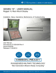
USER MANUAL
COMMAND CONSOLE USER MANUAL
COMMAND CONSOLE 19”
Command Console EDT (Embedded Desktop) & ERM (Embedded Rack Mount)
Installation, Setup, Operations, Maintenance, & Troubleshooting
User Manual
Document # 27-0026UM Rev C
Issued 10/2004
Rev C Released 02/12/2012
RUGGEDIZED MILITARY TECHNOLOGY
“Next Generation Mission-Ready Computing”
Z Microsystems, Inc. · 9820 Summers Ridge Road, San Diego, CA 92121 · T: 858.831.7000 · F: 858.831.7001 · www.zmicro.com
Z Microsystems
COMMAND CONSOLE USER MANUAL
REGULATORY INFORMATION
WARNING
TO PREVENT FIRE OR SHOCK HAZARDS, DO NOT EXPOSE THIS UNIT TO RAIN OR MOISTURE. ALSO, DO NOT USE THIS UNIT’S POLARIZED
AC PLUG WITH AN EXTENSION CORD RECEPTACLE OR OTHER OUTLETS UNLESS ALL THREE PRONGS CAN BE FULLY INSERTED
1. Use the power and video cables supplied
with the product to help prevent interference
with radio and television reception. The use of
cables and adapters may cause interference
with electronic equipment in the vicinity of this
unit.
2. This equipment has been designed to meet
severe conditions in military environments as
specified in MIL-STD-810G, MIL-STD-461F and
DO-160F.
3. This equipment is designed to meet the
limits for Class A digital devices imposed by Part
15 of FCC rules. These limits are designed to
provide reasonable protection against harmful
interference when equipment is operating in
commercial environments. This equipment
generates, uses and can radiate radio frequency
energy, and, if not installed and used in
accordance with the instruction manual,
may cause harmful interference to radio
communications.
CAUTION
RISK OF ELECTRIC SHOCK - DO NOT OPEN
CAUTION: TO REDUCE THE RISK OF ELECTRIC SHOCK DO NOT REMOVE
COVER (OR BACK OF UNIT). NO USER SERVICEABLE PARTS INSIDE. REFER
SERVICING TO QUALIFIED PERSONNEL.
This symbol warns the user that insulated voltage within the unit may have sufficient
magnitude to cause electric shock. Therefore, it is dangerous to make any kind of
contact with any part inside this unit.
This symbol alerts the user that important literature concerning the operation and
maintenance of this unit has been included. Therefore it should be read carefully in
order to avoid any problems.
4. Operation of this equipment in a residential area is likely to cause interference in which case the user will be required to correct the interference at his
own expense. Changes or modifications not expressly approved by Z Microsystems could void user’s authority to operate the equipment.
2
Z Microsystems
COMMAND CONSOLE USER MANUAL
TABLE OF CONTENTS
SectionPage
1.0 Product Overview............................................................................................................................................................ 4
1.1 About This Manual.............................................................................................................................................. 4
1.2 Visual Notifications.............................................................................................................................................. 4
1.3 Product Description............................................................................................................................................ 5
2.0 Installation & Setup.......................................................................................................................................................... 6
2.1 Shipment Contents............................................................................................................................................. 6
2.2 Installation.......................................................................................................................................................... 6
2.2.1 Installation for the Command Console EDT......................................................................................... 7
2.2.2 Installation for the Command Console ERM........................................................................................ 8
2.3 Connections..................................................................................................................................................... 10
3.0 Operations..................................................................................................................................................................... 13
3.1 Deploying the Command Console.................................................................................................................... 13
3.1.1 Deploying & Stowing the Command Console EDT............................................................................ 13
3.1.2 Deploying the Command Console ERM............................................................................................ 14
3.1.3 Stowing the Command Console ERM............................................................................................... 15
3.1.4 Powering Up the Backlight............................................................................................................... 16
3.2 Adjustments and Other Operations................................................................................................................... 16
3.2.1 Adjusting the Monitor Tension........................................................................................................... 16
3.3 Display Panel Control Buttons.......................................................................................................................... 17
3.3.1 Push Button Controls....................................................................................................................... 17
3.3.2 Status Indicators............................................................................................................................... 17
3.4 On Screen Display Menus................................................................................................................................. 18
3.5 Picture In Picture (PIP) Menus........................................................................................................................... 20
3.5.1 PIP Main Menu................................................................................................................................. 20
3.5.2 DVI-I PIP Menus............................................................................................................................... 20
4.0 Maintenance.................................................................................................................................................................. 22
4.1 Cleaning the Command Console...................................................................................................................... 22
4.2 Updates, Upgrades, & Downloads.................................................................................................................... 22
5.0 Troubleshooting............................................................................................................................................................. 23
5.1 Troubleshooting Topics..................................................................................................................................... 23
6.0 Customer Support......................................................................................................................................................... 26
6.1 Contact Information.......................................................................................................................................... 26
6.2 Parts Replacement........................................................................................................................................... 27
7.0 Appendix....................................................................................................................................................................... 28
7.1 Technical & Environmental Specifications.......................................................................................................... 28
7.2 Mechanical Outlines.......................................................................................................................................... 29
3
Z Microsystems
COMMAND CONSOLE USER MANUAL
1.0 PRODUCT OVERVIEW
This section will provide information and assistance with the following topics:
• About This Manual
• Visual Notifications
• Product Overview
1.1 ABOUT THIS MANUAL
This user’s manual provides information about operation, features, installation, connections,
troubleshooting, product replacement, limited warranty, and other important details relevant to
the Command Console EDT/ERM. We recommend you read this manual carefully and follow the
instructions in the installation chapter for verification of system functionality.
This manual and others, as well as other resources are also available on the Z Microsystems
website at www.zmicro.com. For further assistance please visit the Troubleshooting &
Frequently Asked Questions section within the manual, or refer to the section dedicated to
Customer Support.
SAFETY PRECAUTIONS
DANGER: To avoid shock hazard:
•
Do not remove the covers around
the Command Console EDT/ERM.
•
Do not connect or disconnect
the Command Console during an
electrical storm.
•
The power cord plug must be
connected to a properly wired and
grounded power outlet.
•
Any equipment to which the
Command Console will be attached
must also be connected to properly
wired and grounded power outlets.
For added convenience and safety, you will find bookmarks, embedded visual cues for quick
tips, warnings, new sections, and safety precautions. These are intended for quick supplemental
reference and added ease in the installation and operation of the Command Console.
Please refer to the included Z Microsystems Command Console Quick Start Guide for help with
setup and operation of your Command Console Station.
1.2 VISUAL NOTIFICATIONS
WARNINGS AND SAFETY PRECAUTIONS
NOTES AND PREPARATIONS
Necessary Tools
Necessary Hardware
Additional assistance for the Command Console and other Z Microsystems
products can be found on the Z Microsystem’s website along with highly customizable integration options for a wide range of platforms and applications.
4
Z Microsystems
COMMAND CONSOLE USER MANUAL
1.3 PRODUCT DESCRIPTION
Embedded Desktop
Embedded Rack Mount
Rugged C4ISR Workstation
The Command Console Embedded Desktop (EDT) and Embedded Rack Mount (ERM) are designed to be embedded or
fixed to any desk top or rack mount, respectively.
The Command Console EDT and ERM are ideal solutions for integrators building quick-deployable C4ISR systems. The
Command Console brings together a 19” (1280 x 1024) flat panel display with water-tight integrated keyboard and trackball
as a rugged operating station solution.
Additional features include user programmable dual-function on screen menu buttons which can be toggled to send
commands via the serial port on the rear to components.
Rapid Deployment
The Command Console EDT & ERM models are equipped with dual quick-lock/release mechanisms to hold the display
panel firmly in the closed position and allow it to be quickly flipped open and operational. A custom torque adjustable hinge
holds the display securely at any viewing angle, in the most turbulent conditions. An optional picture-in-picture outputs can
be added to display more video feeds and reduce the number of total display requirements.
The Command Console EDT and ERM are manufactured entirely from lightweight, aircraft grade, CNC machined aluminum
and finished with a tough, baked powder coating to provide the utmost strength, durability, and light-weight in quick
deployed situations.
HIGHLIGHTS
•
•
•
•
•
19” 1280 x 1024 LCD Display
•
Durable CNC machined-aluminum
1U, 2U Embedded Rack Mount -or- •
2U Embedded Desktop Option
•
Integrated keyboard and trackball
•
Rugged spring-loaded locks for secure stowing
Ultra-secure, locking DVI-I video and
MIL-round power connectors
Locking PS2 support bracket
On screen display menus for configuration
Field replaceable peripheral components
5
Z Microsystems
COMMAND CONSOLE USER MANUAL
2.0 INSTALLATION & SETUP
WARNING
This section will provide information and assistance with the following topics:
• Parts included with Command Console Shipment
• Command Console Cable Connections Outline
Using assembly hardware that does
not match specifications may
damage internal components.
• Command Console Setup
2.1 SHIPMENT CONTENTS
Ensure all of the following parts are included in the package upon arrival. Verify all parts have
not been damaged during shipment. If any of the parts are missing or damaged, immediately
contact Z Microsystems Customer Service at 858-831-7040.
• Command Console (EDT or ERM)
SETUP NOTES
For the fastest and easiest
installation of the Command
Console, follow the Installation Guide
provided with your shipment.
• Hardware Kit (If applicable)
• Z Microsystems CD/DVD w/ User Manual, Warranty Info, Product Drivers, and other utilities
• Cable Kit (Refer to your shipment checklist for exact kit)
• (1) MIL-C-5015 power cable
• (2) PS2 interface cable for integrated trackball and mouse
• (2) DVI-I video cable (also accepts DVI-D)
• (1) USB Type B cable
2.2 INSTALLATION
Required Tools for Installation
• #2 Phililips Head Screwdriver with a 10”+ shaft
• 5/16” Nut Driver
TIPS
TRANSPORTATION TIP: Remember
to save the unit’s original shipping
materials. It may be needed to
transport the unit or perform
maintenance on it, at a later date.
PREPARATIONS
In preparation to setting up the
Command Console, turn off the
electrical power to computers and all
electronic devices that will connect
to the unit.
• 5/16 Open-end Wrench
Installation and hardware specifications may vary between configurations and models. For more information not provided in this user manual refer the
Quick Start Guide provided with your product shipment, or contact [email protected] for more specific installation details.
The Command Console ERM chassis is designed and engineered to be rack-capable and fit a standard 19” RETMA rack. Follow the instructions
provided in the following ERM Installation section.
The Command Console EDT chassis is designed for implementation in a variety of applications. It can be hard mounted to a pre-existing operating
station, recessed into a workstation or otherwise fitted to meet your needs. For non-standard installation methods, different hardware is required to
implement the EDT. If your configuration requires that the EDT be mounted using custom rails or parts, please contact your Z Microsystems Sales
Representative for options.
For more information about rail kits or mounting configurations please contact Z Microsystems Customer Service at 858-831-7040, or email us at
[email protected].
6
Z Microsystems
COMMAND CONSOLE USER MANUAL
2.2.1 INSTALLATION FOR THE COMMAND CONSOLE EDT
The Command Console EDT - Embedded Desktop is designed to be installed with ease. The installation process can vary for the Embedded Desktop
depending on the desired location for this rugged workstation solution. This station is often installed on a flat surface and securely bolted down, to be
removed and relocated as needed. Other times it is positioned in a recessed cavity for low-profile, more permanent station capabilities.
6 1 4” (inches)
6 1 4” (inches)
The mounting holes, shown above, are positioned for the installation of the Command Console EDT. These inserts are evenly spaced for easy installation
and support assembly. Other mounting holes are for the purpose of rail attachments for the Embedded Rack Mount version of the Command Console.
When installing the EDT in a static position, the Command Console will rest on top of the
surface and be bolted down to it using rail attachment hardware. (As illustrated in the
picture to the left)
When installing the EDT into a recessed cavity for low-profile Command Console operation,
machining or other accomodations will need to be made to secure the Command Console
into place. (not pictured)
Example of static top-mounted
Command Console EDT
Continue to the next page...
7
Z Microsystems
COMMAND CONSOLE USER MANUAL
2.2.2 INSTALLATION FOR THE COMMAND CONSOLE ERM
SLIDE INSTALLATION
1. The first step is to remove the outer
rack mounting slide channels from the
Console.
2. Press the spring loaded locks toward
the middle to release the outer rack
mount slide channels and at the same
time slide the rack mounting block back.
3. Slide the channels back until they stop
about half way back. This is a safety stop
to prevent the Console from sliding out
too far while mounted to the rack.
4. Simultaneously press in the first set
of safety catches on each slide rail and
slide the channel until the second safety
catches stop the sliding action.
5. Repeat these steps to remove the
second rack mount slide channel.
6. The slide extenders come in 16-20”,
21-25”, and 26-30” ranges, The latter two
will not come pre-assembled. Note the
configuration in the above picture when
assembling.
7. Using a 5/16 open-end wrench and
Phillips Head Screwdriver, remove the
four screws holding the two parts of the
rail slide together, as shown above.
8. Slide the assembly rail on to fit the
rack length and reinstall the screws.
9. Mount the channels on the front of the
RETMA rails (in most cases), use three
10-32 Phillips screws on each side.
8
Z Microsystems
7. Secure the screws as shown here. Be
sure to press the slide rail flat against
the RETMA rail as you tighten the
screws.
COMMAND CONSOLE USER MANUAL
9. On the rear of the cabinet frame, use
two 10-32 Phillips screws to secure the
rail. Repeat on the other rail.
8. On the slide rails, using a screwdriver
and wrench, tighten the slide extension
rail screw from the interior of the rack.
Repeat on the other rail.
1. Pull the two Console slides out until
they lock in the second lock position.
2. Hold the Console by each side, with
the front toward you and as horizontal as
possible.
3. Guide the Console’s inner slide
member into the middle slide member,
and gently slide the Console into the
slide assembly until it stops.
4. Simultaneously press in the catches
(one on each side) and slide the channel
until the safety catches stop the sliding
action.
5. Slide the Console into place.
6. The Console should look like this at
this point. It is now successfully installed.
CONSOLE INSTALLATION
9
Z Microsystems
COMMAND CONSOLE USER MANUAL
2.3 CONNECTIONS
There are six connections on the rear panel of a standard Command Console configuration. This section covers cabling requirements , and
the process of connecting the Command Console for Operation.
Connect the appropriate cables and peripheral devices on the rear panel, as instructed below:
REQUIRED CABLING EQUIPMENT
• (1) MIL-C-5015 power cable
• (2) PS2 interface cable
• (2) DVI-I video cable (also accepts DVI-D)
• (1) USB Type B cable
COMMAND CONSOLE CONNECTIONS GUIDE
1
2
3
4
5
6
7
REAR CONNECTIONS KEY
#
Label
Connector Type
1
J5: POWER
MIL-C-5015 round locking connector
2
TRACKBALL
PS2 peripheral connection
3
Locking Support
Secure locking mechanism for PS2 cables
4
KEYBOARD
PS2 peripheral connection
5
J3: VIDEO CH B
DVI-I Dual Link (dual-link connector only *DOES NOT SUPPORT DUAL LINK*)
6
J1: VIDEO CH A
DVI-I Dual Link (dual-link connector only *DOES NOT SUPPORT DUAL LINK*)
7
J2: HOST
USB Type B connector
CONNECTIONS CHART
MIL-C-5015 Round Locking Connector
PS2 Connector
DVI Connections (DVI-D & DVI-I Accepted)
USB Type B Connector
10
Z Microsystems
COMMAND CONSOLE USER MANUAL
CONNECTING THE COMMAND CONSOLE
This section will guide you through the connections por tion of setup for the Command Console. Before operating the unit we will
connect a mil-round power connector, ps2 inter face connectors for the integrated trackball and mouse, dvi cable(s) for up to t wo
video signals, and a USB t ype b connector for communication with the host computer.
Connecting the Power Cable
NOTCH
1. First connect the MIL-C-5015 locking
connector to the unit. Note the notch in
the connector face.
2. Align the notch in the connector
(down), as shown in the picture above.
3. After aligning the power connector,
securely fasten the cable by tightening
the locking mechanism to the J5: POWER
position.
Connecting and Securing the PS2 Interface Cables
1. First, remove the fastening harness
from the PS2 locking support.
2. Attach both PS2 cables that were
included with your shipment for operation
of the trackball and keyboard.
3. When both of the PS2 interface
cables are securely connected, return
the fastening harness to the PS2 locking
support. This will secure the cables,
effectively locking them into place.
11
Z Microsystems
COMMAND CONSOLE USER MANUAL
Connecting DVI Cables for Video Signals
1. The Command Console requires at
least one video signal for functionality.
Taking the DVI-I cables included in your
shipment, attach them as follows.
2. Connect the first DVI cable to J1:
VIDEO CH A. Tighten the locking screws
to prevent the DVI connector from
coming loose.
3. Connect the second DVI cable to J3:
VIDEO CH B. Once again, securely fasten
the connector using the locking screws.
Connecting the USB Type B Cable for Host Communications
1. Lastly, connect the USB Type B
interface cable so that the Command
Console can communicate with your
host computer.
THE COMMAND CONSOLE IS NOW CONNECTED AND READY FOR OPERATION!
12
Z Microsystems
COMMAND CONSOLE USER MANUAL
3.0 OPERATIONS
This section will provide information and assistance with the following topics:
• Deploying the Command Console
• Operating the On Screen Display Menus
• Adjusting Monitor Tension
• Operating the PIP OSD Menus
• Display Panel Control Buttons
NOTE
The Command Console EDT lock
housing has a cover that encloses
the rack locking mechanism.
3.1 DEPLOYING THE COMMAND CONSOLE
The mechanical principle of thes locks is similar to that of spring-loaded dead bolts. Two stainless steel compression springs
in each lock press against the bolt so that it will not come loose even under circumstances of substantial force. The catch (t wo
catches on ERM consoles) releases when the release tab is operated, compressing the springs holding the catch in place. Using
both hands compress both release tabs on either side to open the display.
KEY
#
Lock Part/Function
1
Lock Release Tab
2
Slide cover
3
Spring-loaded locking catch (2 on ERM)
COMMAND CONSOLE LOCKS
1
2
3
(Command Console EDT shown above)
(Command Console ERM shown above)
3.1.1 DEPLOYING THE COMMAND CONSOLE EDT - FOLLOW THESE INSTRUCTIONS:
The Command Console EDT is a rugged embedded desk top solution, mounted
securely as an operating station and connected to a host ser ver or workstation.
Deploying the Command Console is achieved by compressing both release tabs
and folding out the display panel, similar to that of any market-standard laptop or
notebook.
STOWED & SECURED
DEPLOYED
13
Z Microsystems
COMMAND CONSOLE USER MANUAL
3.1.1 DEPLOYING THE COMMAND CONSOLE EDT (CONTINUED)
1. Begin by facing the Command
Console as if in the operating position.
(Command Console would be securely
installed at this point)
4. Adjust the display to the desired angle
and height. The Command Console
is now ready to be powered on and
operated.
2. While positioned like this, compress
each of the lock release tabs by pushing
them towards one another. Compressing
the tabs will release the spring-loaded
catch.
3. With the release tabs compressed,
lif t the upper display panel away
from the embedded keyboard and
trackball.
DEPLOYMENT COMPLETE!!
3.1.2 DEPLOYING THE COMMAND CONSOLE ERM
1. To pull out the Command Console
ERM, place your hands so that your
palms face upwards. Your thumb should
be on the tab of the lock.
2. Rest your fingers under the pull-out
bar as shown. Push the tabs towards
each other and pull out the console with
your fingers until the first safety catch
stops the slide action.
3. Press both slide catches inward
and pull the console out. Pull out the
unit all the way.
14
Z Microsystems
COMMAND CONSOLE USER MANUAL
3.1.2 DEPLOYING THE COMMAND CONSOLE ERM (CONTINUED)
4. Slide the tabs inward and lift the
monitor upward simultaneously.
5. Continue lifting the monitor with the
right hand. Because the monitor is built
for rugged environments, force may be
necessary to lift the monitor into the
upright position.
6. Push the monitor upright to a
comfor table viewing position. Refer to
the nex t section for monitor tension
adjustments as needed.
3.1.3 STOWING THE COMMAND CONSOLE ERM
1. To fold down the console, stand
slightly to the right of the unit and lower
the panel down on its back into the tray.
2. Lay the panel fully down and release
so that the panel becomes locked in the
horizontal position.
4. Press the locks inward while pressing
the Console further into the rack.
5. Release the locks. The Command
COnsole should be fully locked and
stowed away in the storage position.
3. With a hand on the lef t and right
sides of the Console, slide it into the
rack. Push into the seated position.
15
Z Microsystems
COMMAND CONSOLE USER MANUAL
3.1.4 POWERING UP THE BACKLIGHT
The Command Console is now ready for operation. With the unit appropriately connected, press the “Standby” but ton on the
display control panel to turn on the backlight.
PRESS THE STANDBY BUTTON
3.2 ADJUSTMENTS AND OTHER OPERATIONS
3.2.1 ADJUSTING THE MONITOR TENSION
REQUIRED TOOLS TENSION ADJUSTMENT
• 9/64 Hex Wrench
1. Using the 9/64 hex wrench, alternate
making small adjustments between the
two tension screws on each side.
2. Make adjustments clockwise (right)
to tighten the hinge, providing more
support to the erect display.
3. Make adjustments counter-clockwise
(left) to loosen the hinge for more flexible
movement in the hinge.
16
Z Microsystems
COMMAND CONSOLE USER MANUAL
3.3 DISPLAY PANEL CONTROL BUTTONS
NOTE
3.3.1 PUSH BUTTON CONTROLS
The Command Console features push-button controls on the lower front of the display
housing. These buttons provide easy access to the On-Screen Display (OSD) allowing the
user to navigate through menus and adjust image settings.
The control buttons allow the user
to control backlight operations,
to store settings, and to revert to
factory settings.
To setup the display to the desired configuration, use the following controls to fine tune the
image on the screen. SoftMenus may also be available to adjust interface settings from a host
terminal or computer via the USB Type B communications link.
‘Z’
Input Sync
^
Green LED
(Channel A)
>
<
^
Green LED
(Channel B)
Exit
Menu
Status
(Red/Green/Amber)
Standby
Button Functionality Description Table:
Display Key
‘Z’ Input Sync
^
Function
‘Z’ front panel
button will
resync the
main display
image.
Navigates up
to the previous
menu item.
v
<
Navigates
down to the
next menu
item.
Increases
value of the
activated
menu item.
3.3.2 STATUS INDICATORS
>
Decreases
value of the
Selected
Menu Item.
Menu
Activates
On-Screen
Display. Activates/
Deactivates
Selected Menu
Item. (Changes
are saved as they
are modified)
Exit
Exits from On-Screen
Display main menu or
returns from submenu
to main menu. When
the menu is not active,
this button will act as
channel select(Changes
are saved as they are
modified)
Channels LEDs
Status LED
1 — Green — Video A is selected
Green — Power and Signal Sync
2 — Green — Video B is selected
Amber — Power and no Signal
Off — Standby mode / no Power
Power
Press to turn the
backlight ON
and OFF. (Power
Saving Option)
Note: This is NOT
a power switch.
17
Z Microsystems
COMMAND CONSOLE USER MANUAL
3.4 ON SCREEN DISPLAY MENUS
3.4.1 MAIN MENU
MAIN MENU
To access the On-Screen Display main menu, press the menu button on the front of the panel. All
display functions are controlled using the Main Menu’s subtopics.
PICTURE ADJUST
GRAPHICS MODE
These submenus can be accessed for adjustments and information via the display keys on the
bottom panel of the display. Refer to the following sections for specific operations and utilities that
are provided in each of the submenus.
COLOR BALANCE
CONFIGURATION
INFORMATION
ADVANCED OPTIONS
PIP MENU
3.4.2 MAIN SCREEN PICTURE ADJUST
PICTURE ADJUST
MAIN
CH 1
MAIN BRIGHTNESS
MAIN CONTRAST
0
100
0
100
To adjust the display brightness and contrast use the ^ and v buttons to highlight the “Picture Adjust”
option. Press the “Menu” button to access the submenu.
Navigate to the desired option using the ^ and v buttons. Use the Menu button to activate the option.
(Background color of the slider will change when the option is selected.) Use the ^ and v buttons to
increase or decrease the value. Press Menu button again to deactivate the option. This will save any
changes.
(NOTE: Contrast is not available for digital signal images and “Main Contrast” option will be grayed
out and unavailable.)
3.4.3 MAIN SCREEN GRAPHICS MODE
To make adjustments to the display images positioning, width, or the video sampling clock use the ^ and v buttons to highlight the “Graphics Mode”
submenu. Press the “Menu” button to access the “Graphics Mode” submenu.
GRAPHICS MODE
MAIN
CH 1
HORIZ. COARSE
HORIZ. FINE
VERT. POSITION
HORIZ. POSITION
0
100
0
100
0
100
0
100
The “Graphics Mode” menu is used to adjust the positioning of the image. Highlight the desired
option using the ^ and v button. Use the Menu button to activate the option. (Background color of
the slider will change.) Use the ^ and v buttons to increase and decrease the value of the selected
option, respectively. Adjust the image to desired specifications and press menu again when finished
to deactivate the option.
The “Horz Coarse” option adjusts the horizontal width of the image.
The “Horz Fine” option adjusts the phase of the video sampling clock.
Press “Exit” to return to the Main Menu. The new adjustments will be applied automatically.
(NOTE: The Horz Coarse and Horz Fine options are not applicable for digital channels).
3.4.4 MAIN SCREEN COLOR BALANCE
To adjust the color of the display use the ^ and v buttons to highlight the “Color Balance” submenu. Press the “Menu” button to access the
“Color Balance” submenu.
COLOR BALANCE
MAIN
CH 1
RED
GREEN
BLUE
0
100
0
100
0
100
Highlight the color balance submenu using the ^ and v buttons. Use the Menu button to activate the
desired option. (Background color of the slider will change.) Use the ^ and v buttons to increase or
decrease the value. Press menu again to deactivate the option.
Press “Exit” to return to the Main Menu. The new adjustments will be applied
automatically.
(NOTE: Color Balance menu topics Red, Green, and Blue adjustments are available only for analog
signal images. Menu topics will be unavailable and grayed out for digital signals)
18
Z Microsystems
3.4.5 CONFIGURATION SCREEN
CONFIGURATION
MAIN
MENU TIMEOUT
0
100
fACTORY SETTINGS
CHANNEL 1 T YPE:
ANALOG
CHANNEL 2 T YPE:
ANALOG
CHANNEL SELECT:
CHANNEL 2
SCALE MODE:
NORMAL
COMMAND CONSOLE USER MANUAL
Menu Timeout:
This is the amount of time the menu will remain displayed before timing out and disappearing from the
screen. Timeout varies from 4-5 seconds (at 0) up to roughly 4 minutes (at 99). At the 100 setting,
the menu will not timeout. It will disappear only when toggled off by the operator.
Reset Default Settings:
Resets all Main Menu settings to the factory default settings.
Channel Type:
Channel Type sets the DVI-I Channel to accept either analog or digital input.
Channel Select:
The Command Console Display has two channel options. Highlight “Channel Select” and press
Menu button to change channels.
Scale Mode:
There are three scale modes: NORMAL, SCALED ASPECT RATIO (SAR), and NO SCALE. NORMAL mode scales the source image to the full panel size and
aspect ratio. SAR mode will keep the aspect ratio of the incoming signal and use the maximum image size possible for the source aspect ratio. NO SCALE
mode uses the native source resolution and aspect ratio and displays the image without scaling. SAR and NO SCALE images are centered on the
panel with black bars on the sides where no image is present.
3.4.6 ADVANCED OPTIONS SCREEN
ADVANCED OPTIONS
MAIN
These options are available for operation and the future development of Z Microsystems’ Real-Time
Enhanced Video proprietary video enhancement technology.
RTEV SETTINGS
RTEV Settings:
Only available on RTEV-embedded displays. Please contact your Z Micro Sales Rep for more
information.
RTEV GEOMETRY
OSD OPTIONS
RTEV Geometry:
Only available on RTEV-embedded displays. Please contact your Z Micro Sales Rep for more
information.
3.4.7 OSD OPTIONS
OSD Options allows you to modify OSD menu settings to adjust the vertical and horizontal position
as well as the transparency of the On-Screen Display.
OSD OPTIONS
MAIN
VERT POSITION
HORIZ POSITION
0
100
0
100
Vert Position:
Vert Position allows the user to change the position of the OSD screen in vertical position (Y-axis).
Horiz Position:
Horiz Position allows the user to change the position of the OSD screen in horizontal position (X-axis).
3.4.8 MAIN SCREEN INFORMATION
WARNING
It is advised to contact Z
Microsystems Customer Support if
the temperature exceeds 65C.
Use the ^ and v buttons to highlight the “Information” option. Press the “Menu” button to access the
“Information” submenu.
Within this submenu, the user can view firmware version, build date, incoming video signals, and
display operating temperature.
Temperature displayed is the onboard circuit-board temperature. Temperature variation is common
and expected.
19
Z Microsystems
COMMAND CONSOLE USER MANUAL
3.5 PICTURE IN PICTURE (PIP) MENUS
3.5.1 PIP MAIN MENU
The PIP main menu can be accessed through the OSD Main Menu using the same front panel control
buttons throughout the OSD. Using the Control Panel buttons, select the PIP Menu.
PIP MENU
From this menu, there is one option: DVI-I PIP. Use the directional buttons to select the proper menu
and use the ‘menu’ button to activate/select the chosen menu.
DVI-I PIP
These submenus can be accessed for adjustments and information via the push button display
controls on the bottom panel of the display. The following sections detail the adjustments and
operations of DVI-I PIP windows.
3.5.2 DVI-I PIP MENUS
From the DVI-I PIP Menu, the user can select and make adjustments to the DVI-I PIP channel.
PIP Select:
No change is available for DVI-I PIP Select.
DVI-I PIP MENU
PIP # 2
PIP SELECT
Geometry:
This menu sets size and position of the PIP window, as well as image position within the window.
2
GEOMETRY
Video Settings:
This menu offers adjustment levels for contrast, brightness, color, and tint in the selected PIP
channel.
VIDEO SETTINGS
CONFIGURATION
INFORMATION
Configuration:
Use this menu to enable/disable the PIP channel, restore factory settings, and turn chroma key use
on and off.
Information:
This menu displays PIP firmware info and date, part number, and current resolution status.
DVI-I PIP GEOMETRY
The DVI-I PIP Geometry menu can be used to adjust the size and positioning of the DVI-I PIP window
and the picture displayed by the channel.
GEOMETRY
PIP # 2
PIP SIZE
0
85
100
0
100
100
0
0
100
0
25
50
0
25
50
PIP HORIZ POS
PIP VERT POS
IMAGE HORIZ POS
IMAGE VERT POS
PIP Size:
This will increase/decrease the overal size of the DVI-I PIP window while maintaining current aspect
ratio.
PIP Horiz Position:
This option adjusts the horizontal (X-axis) location of the DVI-I PIP window.
PIP Vert Position:
This option adjusts the vertical (Y-axis) location of the DVI-I PIP window.
Image Horiz Position:
This option will adjust the horizontal (X-axis) location of the displayed image within the DVI-I PIP.
Image Vert Position:
This option will adjust the vertical (Y-axis) location of the displayed image within the PIP window.
DVI-I PIP VIDEO SETTINGS
The DVI-I PIP Video Settings menu is used to adjust contrast, brightness, color, and tint.
Contrast:
This option will adjust the balance of light and dark colors as well as light brightness of an image.
VIDEO SETTINGS
PIP # 2
CONTRAST
0
100
100
0
050
100
0
050
100
BRIGHTNESS
COLOR
TINT
0
000
50
Brightness:
This ‘Brightness’ option adjusts the light intensity level of the display.
Color:
This option will adjust the SMPTE color balance of the image to achieve
Tint:
This option will adjust the horizontal (X-axis) location of the displayed image within the PIP window.
20
Z Microsystems
COMMAND CONSOLE USER MANUAL
DVI-I PIP CONFIGURATION
CONFIGURATION
PIP # 2
PIP ENABLE:
OFF
Factory Settings:
This option will reset the PIP channel with default factory settings.
FACTORY SETTINGS
CHROMA KEY:
The DVI-I PIP Configuration menu allows the user to enable/disable the DVI-I PIP channel, default this
channel to factory settings, and turn on and off the chroma key functions.
PIP Enable:
This option will turn on and off the selected DVI-I PIP channel.
OFF
Chroma Key:
This option toggles on and off the Chroma key functions, a built in color coded image overlaying
process.
DVI-I PIP INFORMATION
INFORMATION
PIP # 2
Users can find current system firmware version and date information, as well as part number and
visual queues for current resolution status in this DVI-I PIP Information menu.
Z MICROSYSTEMS INC.
WWW.ZMICRO.COM
FIRMWARE:
ZDHC 50C2 02/12/12
PART NUMBER:
32-00104
RESOLUTION:
INVALID
NTSM-MJ
21
Z Microsystems
COMMAND CONSOLE USER MANUAL
4.0 MAINTENANCE
This section will provide information and assistance with the following topics:
• Cleaning the Command Console
• Updates & Upgrades
CAUTION
Do not use benzene, thinner, ammonia
or any volatile substance to clean the
unit housing. These chemicals may
damage the unit.
WARNING
Be sure to turn off the power before you
perform any maintenance on the unit.
WARNING
It is recommended that users do not
service the Unit. User maintenance is
restricted to removal and installation
of modules and COTS parts, and to
cleaning as explained below.
4.1 CLEANING THE COMMAND CONSOLE
Disconnect the Command Console from the power source before cleaning.
• Clean the surface of the Command Console with a soft, clean cloth, lightly dampened with water or mild detergent.
• Wipe the display and external surfaces until clean. Use a soft lint-free cloth and isopropyl alcohol to clean .
4.2 UPGRADES AND FIELD REPLACEMENTS
Disconnect the Command Console from the power source before performing any operations on the Command Console.
The Command Console platform was designed to accomodate for field replacement of the integrated trackball and keyboard, without the use of special
hardware or tools. This allows for market-standard COTS or other parts to be purchased and installed as needed for future program needs. Please note
that performing any operations other than those expressly written in Z Microsystems warranty agreement may void the protection plan coverage.
22
Z Microsystems
COMMAND CONSOLE USER MANUAL
5.0 TROUBLESHOOTING
This section will provide information and assistance with the following topics:
• Troubleshooting Topics for the Command Console
• Frequently Asked Questions about the Command Console
5.1 TROUBLESHOOTING TOPICS
No Main Display Image
If there is no image displayed on the main screen, a signal will appear that reads “No Sync, Please Check the Cable”. If the cable from the computer to the
display is secure, determine the color of the standby LED light and follow the appropriate procedure described below.
Black - Cause: If the status LED is black (unlit), the unit is on standby or is not receiving power.
Recovery:
• Press and hold standby button.
• Ensure the power cable is plugged into the source.
• Connect the power cable to a AC outlet. Ensure the AC outlet is active.
• Turn on the display’s backlight by pressing the standby button.
Amber - Cause: If the status LED is amber, there is power but no video signal is being received.
Recovery:
•If Video 1 or Video 2 is selected, ensure there is a video signal coming into the selected channel.
•Ensure there is a video signal coming from the computer.
•Be sure the channel type is set correctly for the video signal that is provided by the graphics card. Confirm that the display is setup to analog or digital
and verify the outgoing signal from the host computer matches this signal type.
Green - Cause: When the status LED is green, there is both power and a video signal. If there is still no image, follow these recovery steps:
Recovery:
• Ensure the video signal coming from the computer is not a black screen.
• Ensure the Channel Type is selected corresponding to the incoming video signal.
• Ensure the Channel Type under “Configuration” in the OSD menu corresponds to the signal type (i.e. ANALOG or DIGITAL).
• Make sure the right cable is being used for the incoming video signal. DVI-D will not support an ANALOG signal.
• Try a known supported video source resolution and frequency as listed in the Appendix for specifications.
• If these Recovery criteria have been met and the issue is not resolved there is potentially a hardware failure.
Display Image has Poor Color or Brightness (Analog Signal Issue)
Possibe Recovery:
Red, Green, and Blue gains can be adjusted from the Color Balance menu topic within the OSD Main Menu. Best quality color is generally achieved when
red, green, and blue gains are balanced and all at similar levels. In the Picture Adjust submenu, ensure “Main Brightness” setting is at a sufficient level.
Display Image Has Vertical Bars (Analog Signal Issue)
Possibe Recovery:
If the main image begins to display vertical bars, adjust the “Horz Coarse”. From the Main Menu, use the Up and Down buttons to highlight the “Graphics
Mode” option. Select the “Graphics Mode” submenu and use the left and right arrow buttons to adjust the screen until the number of bars is reduced.
Continue adjusting one step at a time until the bars are no longer visible.
Make sure that the connectors are seated properly on the back of the Command Console display. “Horz Coarse” option is only available for Analog video
signals.
23
Z Microsystems
COMMAND CONSOLE USER MANUAL
Display Image Has Horizontal Bars (Analog Signal Issue)
Possible Recovery:
If the main image begins to display horizontal bars, check that the video input cable is securely attached to the back of the monitor. If this does not
resolve the issue there is a chance the connector cable is damaged or defective. Try replacing the DVI cable with a new one to see if the bars disappear.
Display Image Appears Fuzzy / Poor Quality (Analog Signal Issue)
Possible Recovery:
If the main image begins to appear fuzzy or “noisy”, adjust the “Horz Fine” until it is reduced. The “Horz Fine” option adjusts the phase of the
video sampling clock. To access the “Horz Fine” submenu from the Main Menu, use the up and down arrow buttons to highlight the “Graphics Mode”
option. Press the “Menu” button to access the “Graphics Mode” submenu. The “Horz Fine” and “Horz Coarse” options are only availabe to ANALOG
video sources.
If the configuration screen reads ANALOG for the Channel Type and the user is expecting a DIGITAL signal, then the display may not be
receiving a digital signal that it can understand. This problem may result from an incompatibility in the graphics card. The source graphics
card may not be certified to full DVI-I specification and may be defaulting to an analog signal. One option is to change the configuration in the
graphics card to transmit only a DVI-D signal. A second option is to use a DVI-D cable to connect the host system to the display.
Possible Recovery:
In some cases, poor image quality may be caused by a break in the connection. Check for potential breaks by looking for damage or frays to the
cable, particularly near connector heads. Also check connector pins to ensure that they are properly aligned to fit into the designated connector
jack. If the problem persists, try replacing the video cable.
Possible Recovery:
Some electronics and cellular devices generate electrical/radio interference. The problem may result from close proximity to such a device. Be
sure that all items that may cause interference are kept away from the display.
Possible Recovery:
Low signal level is a potential cause for poor image quality. If the previous processes have not resolved the issue, try connecting the display to a
video source that provides a clear picture to another display. This will rule out variables and narrow troubleshooting direction.
Possible Recovery:
Make sure that video cables are properly seated on the back of the display panel. A bad seating can have the RGB connectors misaligned. These
RGB options are only available for Analog video signals. In the event that these color adjustments have been changed and are out of balance Reset menu settings to default.
Display Image is Not Centered
If the main image is not centered on the display, access the “Graphics Mode” menu in the OSD. Using the ‘+’ and ‘-’ buttons adjust the ‘Vert’ and
‘Horz’ position until image is appropriately centered.
If the OSD is not positioned in a desired location, an independent menu for OSD options can be found within the “Advanced Options” menu.
Problems with Analog Signal Resolution at 1920x1200x60
Possible Recovery:
This issue is generally resolved by designating the correct signal format (digital or analog) under Channel Type in the Configurations OSD menu.
This communicates to the display the correct Extended Display Identification Data (EDID) information. The settings are passed on to the Graphics
Card and 1920x1200x60 reduced blankoing is produced by the graphics card.
Be sure that the EDID information is passed to the graphics card and that your graphics card recognizes the Command Console Display as a
“ZMicro display.”
24
Z Microsystems
COMMAND CONSOLE USER MANUAL
No Picture-in-Picture Option Appears on Main Menu
If no PIP menu is available from the Main Menu, the PIP has not been detected by the controller. Recycle power to the unit by disconnecting power and
then reconnecting power. If no PIP is detected again when the Main Menu is powered up again, call Z Microsystems’ Customer Support Department for
assistance.
No Picture-in-Picture Image
There are a few scenarios which may cause the image on the PIP to be black. To eliminate these concerns, follow the instructions below in the order they
are presented:
1. Ensure the PIP is viewing something with contrast and shape and can be easily detected under normal viewing conditions.
2. If the PIP is viewing something with these quality, and should be easily detected, the values associated with Contrast and Color Balance may require adjustment. To ensure the Contrast and Color Balance values are not the cause of the black screen, set the values to the factory default settings.
3. In some Command Console EDT and ERM configurations, there are two inputs for the RGB channel and one input for the Video Channel. Ensure that the correct channel is chosen for the desired PIP.
4. If the black screen is for the RGB PIP, perform an Auto Adjust in the PIP submenu
5. If no PIP image appears, call Z Microsystems’ Customer Support Department for assistance.
25
Z Microsystems
COMMAND CONSOLE USER MANUAL
6.0 CUSTOMER SUPPORT
6.1 CONTACT INFORMATION
Technical Support
If you are unable to correct the problem yourself, contact Z Microsystems at:
Phone: Fax:
Website:
Email: (858) 831-7040
(858) 831-7001
www.zmicro.com
[email protected]
NOTE
For more help topics, late-breaking
news, and information on the latest
products and accessories from Z Micro,
visit us at our website.
www.zmicro.com
Before calling, please have available as much of the following informationa s possible:
1. Model and serial number for the label on the monitor.
2. Purchase P.O.
3. Description of the problem
4. Computer type and model
5. System configuration (hardware fitted, etc.)
6. System BIOS version number
7. Operating System and version number
8. Display driver version number
9. Video Adapter Type
CUSTOMER SERVICE
If possible, stay by the computer. The
Z Microsystems Technical Support
Representative may wish to go through
the problem with you over the phone.
Documentation Assistance
If you are unable to find documentation for your specific product, contact Z Microsystems at:
Phone:
Email: (858) 831-7039
[email protected]
Customer Feedback
We value feedback on our products, their performance, problems found, and welcome all suggestions.
Please send to:
Customer Service
Z Microsystems
9820 Summers Ridge Road
San Diego, CA 92121
(or)
www.zmicro.com
Customer Satisfaction
It is our passion to provide our customers with “Legendary” Products & Services. Your satisfaction is our #1 prioirity. If you have experienced difficulty
during any stage of your Z Microsystems product purchase or use, or would just like to make suggestions, please leave us feedback via our online
Satisfaction Survey.
Please take a moment to complete our Customer Satisfaction Survey at: http://zmicro.com/customersurvey.html
26
Z Microsystems
COMMAND CONSOLE USER MANUAL
6.2 PARTS REPLACEMENT
If the Z Microsystems Technical Support Engineer determines that the product needs to be replaced, a Customer Service Representative will issue a
Return Material Authorization (RMA) number.
An RMA number is required to return a product to Z Microsystems, regardless of the reason for the return.
The Z Microsystems Customer Service Department/RMA Request Form will ask the customer to provide the following information:
• model number of the defective product
• serial number of the defective product
• firmware revision (as detailed in the “Information” section of the Main Menu
• problem with the defective product
• return “ship to” address
• the name and address of the company department to which we will send the invoice (if product is out of warranty or is different from the “ship to”
address.
• phone number and e-mail address of contact
• purchase order number (PO #)
You will be given an RMA number and will be asked to send the product to:
Z Microsystems
ATTN.: (RMA#) It is very important to reference the RMA#
9820 Summers Ridge Road
San Diego, CA 92121
Disclaimer
Z Microsystems warrants that every product is free from defects in materials, workmanship, and conforms to Z Microsystems’ stringent specifications.
Z Microsystems calculates the expiration of the warranty period from the date the product is shipped. This means that the ship date on your invoice is
your product ship date unless Z Microsystems informs you otherwise. During the warranty period, Z Microsystems will provide warranty service under the
type of warranty purchased for the product.
Replacement parts will assume the remaining warranty of the parts they replace. If a product does not function as warranted during the warranty period,
Z Microsystems will repair or replace the part (with a product that is at minimum, functionally equivalent) without charge.
If the product is transferred to another user, the warranty service is available to that user for the remainder of the warranty period.
Z Microsystems’ warranties are voided if the covered product is damaged due to an accident or abuse. The warranty is voided if the product is shipped
with insufficient package protection.
Under no circumstances is Z Microsystems liable for any of the following:
1. Third-party claims against you for losses or damages.
2. Loss of, or damage to, your records or data.
3. Economic consequential damages (including lost profits or savings) or incidental damages, even if Z Microsystems is informed.
Some jurisdictions do not allow the exclusion or limitation of incidental or consequential damages, so the above limitation or exclusion may not apply to
you. This warranty gives you specfic legal rights and you may also have other rights that vary from jurisdiction to jurisdiction.
Warranty does not take effect until full payment is received by Z Microsystems.
27
Z Microsystems
COMMAND CONSOLE USER MANUAL
7.0 APPENDIX
7.1 TECHNICAL & ENVIRONMENTAL SPECIFICATIONS
Display Specifications
Active Display Size
19 inch, SXGA
Native Resolution
1280 x 1024 (Scaled support up to 1920 x 1200 via on board video controller)
Screen Type
LCD (Integrated LED driver board)
Color Palette
8-bit
Contrast Ratio 2000:1
Brightness
600 cd/m 2
Viewing Angle
+/- 89° all angles
Supported Resolutions
640x480x60Hz, 640x480x75Hz, 640x480x85Hz, 1920x1080x60Hz, 1920x1200x60Hz RB, 1600x1200x60Hz, 800x600x60Hz,
800x600x72Hz, 800x600x75Hz, 800x600x85Hz, 1280x768x60Hz, 1280x768x75Hz, 1280x1024x60Hz, 1280x1024x75Hz
1280x1024x85Hz, 1024x768x60Hz, 1024x768x75Hz, 1024x768x85Hz, 1152x864x75Hz, 1440x900x60Hz
Optically bonded Anti-Reflective Shield
Display Options
Physical
Command Console EDT
Size:
Weight: Approximately 23 lbs (24.5 lbs w/ handles attached)
3.40” H x 16.95” W x 16.93” D
Power Supply
AC Power Supply Internal 110/220 VAC Power Supply
DC Power Supply Not yet implemented
Inputs
Video Signal (PIP)
Power
Communication USB Type B Interface
Keyboard/Mouse
PS2 and USB Interface available with securing
CH1: DVI-I (Digital Only) CH2: DVI-I (Digital Only)
MIL-C-5015 series locking connector
Environmental
Shock MIL-STD-810F Section 516.5, 40g’s 11ms saw-tooth Vibration
Operating Temp.
MIL-STD-810G, 0°C to +50°C
Non-Op Temp
MIL-STD-810G -30°C to +70°C
Non-Op Altitude
Up to 40,000 ft
Operating Altitude
Up to 10,000 ft
Operating Humidity MIL-STD-810G Method 507.5, Procedure II, 240 hr duration (10 cycles)
Fungus
Non-Nutrients/Contaminant
Crash Safety
MIL-STD-810G Method 516.5
EMI
MIL-STD-901D Grade A Hammer Test
DO-160 Section 8 curve B - Fixed Winged Aircraft and Surface Ship\
MIL-STD-461F for CS101, CS114 Curve 3, CS115, CS116, RS102, RS103, CE102
Reliability
Operating Life
10 years
Maintainability
<20 minutes at the replaceable unit (LRU) level
Regulatory/Quality
IPC / ISO 9001:2008 and applicable section of MIL-HDBK-454
MIL-SPEC
Improved environmental limitations for military applications can be achieved with additional enhancement options.
28
Z Microsystems
COMMAND CONSOLE USER MANUAL
7.2 MECHANICAL OUTLINES
COMMAND CONSOLE EDT - EMBEDDED DESKTOP
ISOMETRIC VIEW CLOSED
ISOMETRIC VIEW CLOSED
ISOMETRIC VIEW OPEN
29
Z Microsystems
COMMAND CONSOLE USER MANUAL
COMMAND CONSOLE EDT - EMBEDDED DESKTOP (CONTINUED)
6X
1.00
.281
1.230
.730
3X 1/4-20 .31
BOTH SIDES
6.750
6.250
14.49
16.18
14.88
16.15
6.250
6.750
.50
.450
18.300
17.46
1.25
1.69
3.40
16.95
19.45
30
Z Microsystems
COMMAND CONSOLE USER MANUAL
COMMAND CONSOLE EDT - EMBEDDED DESKTOP (CONTINUED)
KEYBOARD
VIDEO CH A
TRACKBALL
AC POWER INPUT
VIDEO CH B
REAR VIEW
HOST
105° MAX
18.319
SIDE VIEW
3.75
31
Z Microsystems
COMMAND CONSOLE USER MANUAL
COMMAND CONSOLE ERM - EMBEDDED RACK MOUNT
ISOMETRIC VIEW CLOSED
ISOMETRIC VIEW CLOSED
ISOMETRIC VIEW OPEN
32
Z Microsystems
COMMAND CONSOLE USER MANUAL
COMMAND CONSOLE ERM - EMBEDDED RACK MOUNT (CONTINUED)
.875
.625
18.112
R.098
18.487
1.00
16.00
TO
30.00
14.87
1.31
3.50
18.95
.625
R.098
18.100
18.440
.250
.625
33
Z Microsystems
COMMAND CONSOLE USER MANUAL
COMMAND CONSOLE ERM - EMBEDDED RACK MOUNT (CONTINUED)
3.730
19.877
105° MAX
34
Z Microsystems, Inc.
9820 Summers Ridge Road
San Diego, CA 92121
Phone: (858) 831-7000
Fax: (858) 831-7001
Website: www.zmicro.com
Copyright 2013 Z Microsystems, Inc. All Rights Reserved


