1
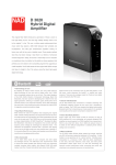
FIELD-READY O R I ON 20 User Manual Z Microsystems Doc# 27-0010UM Issued 02/01 Rev 1.0 Regulatory FCC INFORMATION 1. Use the power and video cables supplied with the Orion to help prevent interference with radio and television reception. The use of cables and adapters may cause interference with electronic equipment in the vicinity of this unit. reasonable protection against harmful interference in when equipment is operated in commercial environments. This equipment generates, uses and can radiate radio frequency energy, and, if not installed and used in accordance with the instruction manual, may cause harmful interference to radio communications. 3. Operation of this equipment in a residential area is likely to cause interference in which case the user will be required to correct the interference at his own expense. Changes or modifications not expressly approved by Z Microsystems could void users authority to operate the equipment. ORION 2. This equipment has been tested and found to comply with the limits for Class A digital devices, pursuant to certain limits imposed by Part 15 of the FCC rules. These limits are designed to provide 20 2 Doc# 27-0010UM Issued 02/01 Rev 1.0 Contents STARTING POINT Shipment Contents User Manual System Requirements Product Description Tools Required Precautions 4 4 4 4 5 6 6 TROUBLESHOOTING SAW Touch Panel 18 20 SPECIFICATIONS Supported Video Modes 23 24 WARRANTY 26 INSTALL ORION Drawings Rear Panel Connectors 7 7 8 SUPPORT Further Help Replacing Parts Providing Feedback 29 29 30 30 MONITOR Controls 9 9 ON-SCREEN MENU 11 Main Menu Navigation 11 Brightness & Contrast Menu 12 Contrast RGB Submenu 12 Color & Gamma Menu 13 Color RGB Submenu 13 Gamma RGB Submenu 14 Position, Size & Focus Menu 14 OSD Position & Language Menu 15 OSD Position Submenu 15 Language Submenu 16 All Reset Submenu 16 Resolution, Hsync & Vsync Menu 17 3 Doc# 27-0010UM Issued 02/01 Rev 1.0 Starting Point Congratulations on selecting a rugged field-ready Orion 20 SHIPMENT CONTENTS USER MANUAL The Orion shipping box contains the following: The User Manual is also available on the Z Microsystems web site (www.zmicro.com). The Orion FPD We recommend you read this manual as follows: User Manual Remember to save your original shipping container and packing material to transport or ship the Orion. Carefully follow the instructions in the Installation chapter for hookup and initial control settings. Refer to the On-Screen Menu chapter for a complete description of all the user controls, and the Troubleshooting chapter for correcting any unforeseen problems with the system. The Specification chapter is provided for quickly finding technical information about the Orion. SYSTEM REQUIREMENTS The Orion works with any computer system that provides industry standard screen formats from 640 x 480 to 1280 x 1024, with up to 85 Hz vertical sync. Required input power is AC 90 - 264 VAC @47 - 440 Hz with a power consumption of 85 Watts. A serial port (COM port) from a host computer will be needed when the touchscreen function is used. 4 Doc# 27-0010UM Issued 02/01 Rev 1.0 Starting Point PRODUCT DESCRIPTION The Orion 20 is a thin, lightweight, rugged direct-mount liquid crystal display. well as weight and size are a driving factor. Each Orion 20 features a transparent SAW TouchScreen over the FPD area, front eight button control panel, and low power usage that extends the life of the monitor as well as emanation protection that make it less susceptible to electromagnetic interference. Designed to replace bulky power guzzling 17 to 21 CRTs. It has a 20.1 diagonal active display area, featuring up to 1280 x 1024 pixel resolution. The Orion 20 display plugs-and-plays with workstations and PCs. Modulated Fan Option In order to maintain proper cooling of the display and its electronics, the Orion 20 monitor includes a variable speed fan that turns on when the monitor control electronics temperature rises to 30o C. The speed of the fan increases gradually, as the temperature rises from 30o C up through 50o C. With active-matrix LCD technology to provide superior color, the lightweight aluminum construction and sharper resolution is perfect for shipboard, airborne, field deployments, industrial or lab applications where high resolution as 5 Doc# 27-0010UM Issued 02/01 Rev 1.0 Starting Point TOOLS REQUIRED Required Tools and Equipment for Mechanical Installation Flat head screwdriver DANGER: To avoid shock hazard: Do not remove the covers around the Orion. Do not connect or disconnect the Orion during an electrical storm. The power cord plug must be connected to a properly wired and grounded power outlet. Any equipment to which the Orion will be attached must also be connected to properly wired and grounded power outlets. PRECAUTIONS In preparation to install the Orion, take the following precautionary steps: Turn off the electrical power to your computer. NOTE: For the fastest and easiest installation of the Orion, follow these steps in the sequence they are presented. 6 Doc# 27-0010UM Issued 02/01 Rev 1.0 DRAWING Install Orion The following drawing shows the Orion 20 from the back, side, top and front. 7 Doc# 27-0010UM Issued 02/01 Rev 1.0 Install Orion Six captive 10-32 screws secure the Raytheon Orion 20 to the rack. REAR PANEL CONNECTORS RGB VGA Connector TouchScreen Connector AC Power Connector AC Power Switch 8 Doc# 27-0010UM Issued 02/01 Rev 1.0 Monitor CONTROLS The Orion features push-button controls on the lower front of the display screen to adjust the brightness of the display, to change the image positioning on the screen, and to refine the screen image. The Orion control buttons allow the user to control image position, clarity and to power on and off the monitor. This section explains how to use the Orion control buttons to adjust the clarity of the display and image position on the screen. In particular it discusses the function of each of the push-button controls. To complete the setup of the Orion, use the following controls to fine tune the image on the screen: There are three LED lights on the right of the control panel. The top two LEDs are not used. The bottom LED is labeled . The lighted functions are: -- Video (green/ orange) Green -- power and signal Orange -- power and no signal Off -- Standby mode 9 Doc# 27-0010UM Issued 02/01 Rev 1.0 Monitor CONTROLS EXIT Exit On-Screen Menu DOWN Move down through menu functions. >>> > > >>> BUTTONS (from left to right) UP Move up through menu functions. Menu MENU Activate On-Screen Menu. Also, use this button to activate the highlighted function. Reset RESET Reset the menu function that is currently selected. < LEFT Move left through menus or adjust value for functions. >>> RIGHT Move right through menus or adjust value for functions. POWER Apply power to the monitor. 10 Doc# 27-0010UM Issued 02/01 Rev 1.0 On Screen Menus MAIN MENU NAVIGATION Use the Right and Left buttons to navigate through the main menus in the heading of the On Screen Menu display. >>> Use the Up and Down button to navigate the various menus or access submenus for each for the five heading menus. >>> <>>> These Heading Menus are: Brightness and Contrast Menu and access point for the Contrast RGB Submenu. Color and Gamma Menu and access point for the Color RGB and Gamma RGB Submenus. Position, Size and Focus Menu. OSD Position and Language Menu and access point for OSD Position, Language, and All Reset Submenus. Resolution, Hsync, Vsync and Input Mode Menu. 11 Doc# 27-0010UM Issued 02/01 Rev 1.0 On Screen Menus BRIGHTNESS AND CONTRAST MENU Brightness < Reduces the Brightness Level > Increases the Brightness Level Contrast < Reduces the Contrast Level > Increases the Contrast Level RGB>> Depress the Menu button to enter the Contrast RGB Submenu. CONTRAST RGB SUBMENU Red < Reduces the Red Contrast Level > Increases the Red Contrast Level Green < Reduces the Green Contrast Level > Increases the Green Contrast Level Blue < Reduces the Blue Contrast Level > Increases the Blue Contrast Level <<BACK Depress the Menu button to go back to the top menu level. 12 Doc# 27-0010UM Issued 02/01 Rev 1.0 On Screen Menus COLOR AND GAMMA MENU Color < Reduces the Color Level > Increases the Color Level RGB>> Depress the Menu button to enter the Color RGB Submenu. Gamma < Reduces the Gamma Level > Increases the Gamma Level RGB>> Depress the Menu button to enter the Gamma RGB Submenu. A.G.C. Depress the Menu button to activate the A.G.C. function. (Automatic Gain Control) COLOR RGB SUBMENU Red < Reduces the Red Color Level > Increases the Red Color Level Green < Reduces the Green Color Level > Increases the Green Color Level Blue < Reduces the Blue Color Level > Increases the Blue Color Level <<BACK Depress the Menu button to go back to the top menu level. 13 Doc# 27-0010UM Issued 02/01 Rev 1.0 On Screen Menus GAMMA RGB SUBMENU Red < Reduces the Red Gamma Level > Increases the Red Gamma Level Green < Reduces the Green Gamma Level > Increases the Green Gamma Level Blue < Reduces the Blue Gamma Level > Increases the Blue Gamma Level <<BACK Depress the Menu button to go back to the top menu level. POSITION, SIZE AND FOCUS MENU H. Position < Moves the image towards the left > Moves the image towards the right V. Position < Moves the image downward > Moves the image upward Size < Compresses the image horizontally > Stretches the image horizontally Focus Use the < button or the > button to adjust the image for maximum clarity. Auto Adjust Depress the Menu button to activate the Auto Adjust function. 14 Doc# 27-0010UM Issued 02/01 Rev 1.0 On Screen Menus OSD POSITION AND LANGUAGE MENU OSD Position Depress the Menu button to enter the OSD Position Submenu. Language Depress the Menu button to enter the Language Submenu. All Reset Depress the Menu button to enter the ALL RESET submenu. [ALL RESET returns all of the On Screen Menu functions to the default settings.] OSD POSITION SUBMENU Use the < button or the > button to adjust the OSD Position. Use the Menu button to save the setting and/or to go back to the top level. 15 Doc# 27-0010UM Issued 02/01 Rev 1.0 On Screen Menus LANGUAGE SUBMENU Use the < button or the > button to change the Language setting. Use the Menu button to save the setting and/or to go back to the top level. ALL RESET SUBMENU Depress the Menu button to activate the ALL RESET function. 16 Doc# 27-0010UM Issued 02/01 Rev 1.0 >>> >>> To return to the top menu level, use the or buttons to highlight CANCEL, then depress the Menu button to go back to the top menu level. On Screen Menus RESOLUTION, HSYNC, VSYNC AND INPUT MODE MENU Displays the current Resolution, Hsync frequency, Vsync frequency, and Input Mode. 17 Doc# 27-0010UM Issued 02/01 Rev 1.0 Troubleshooting 1. Input signal change. Everytime the unit is powered on this message is displayed. ANALOG DIGITAL - NO SIGNAL - 2. NO SIGNAL: NO SIGNAL is displayed for four seconds when there is no video input. SIGNAL SOURCE NO SIGNAL 3. OUT OF RANGE: Each frequency is displayed for four seconds when the Horizontal and Vertical synch signals are outside the range of the monitor. OUT OF RANGE H 9 5. 0 kHz V 6 0. 0 Hz PRESS EXIT KEY 18 Doc# 27-0010UM Issued 02/01 Rev 1.0 Troubleshooting What is the color of the Standby LED? NO IMAGE ON DISPLAY Black -- No power or in Standby mode: Make sure the power cable is plugged in. Connect the power cable to a 110 V outlet, which is turned ON. Wake up the display by pressing the Power button. Orange -- There is power, but no video signal: Make sure the video cable is plugged into the VGA Video connector. Make sure there is a video signal coming out of the computer. Green -- There is power and there is a video signal: Make sure that the video signal coming out from the computer is not a black image. Possible hardware failure. Contact Z Microsystems Customer Support. 19 Doc# 27-0010UM Issued 02/01 Rev 1.0 Troubleshooting SAW TOUCH PANEL OPERATION The SAW (Surface Acoustic Wave) Touch Panel incorporates a glass overlay with transducers that generate ultrasonic waves that are directed over the front surface of the glass. When touched, a portion of the wave traveling across the screen is absorbed. The received signal is compared with a stored digital map, the change recognized and a coordinate calculated. TOUCH PANEL NOT RESPONDING WHEN TOUCHED Verify that the pointing device (if not a finger) is soft enough to absorb the signal. A finger, soft eraser or rubber stylus will work. A hard eraser, pen or metal stylus will not absorb enough of the signal and the touch panel will not respond. Verify that the SAW Panel driver is loaded in the host computer. If loaded, the driver will be found in the Control Panel directory. If not loaded, install the driver. 20 Doc# 27-0010UM Issued 02/01 Rev 1.0 Troubleshooting SAW TOUCH PANEL TOUCH PANEL NOT RESPONDING WHEN TOUCHED After verifying that the ELO Touch Screen driver is installed, verify that the touch panel is responding to the host computer. From the ELO Touch Screen Program, select the Diagnostic tab. If the touch panel is responding, a check mark will be in the Controller Information box next to the COM port menu. If it is not, a red X will appear next to the COM port menu. If a red X appears, verify that the appropriate COM port has been selected and that the serial cable is connected to the touchscreen port of the display unit. If the COM port matches the connection of the host computer and you still get an X when initialized, then verify that the serial cable type is a Straight Connect not Null Modem type. If all of the above is correct then there is something wrong with the touch panel, contact Z Microsystems Customer Service at (858) 657-100 x232 or fill out an RMA Request Form at www.zmicro.com/rma-request.htm 21 Doc# 27-0010UM Issued 02/01 Rev 1.0 Troubleshooting SAW TOUCH PANEL CURSOR NOT RESPONDING If the cursor does not move under the pointer when touched, calibration of the touch panel may be required. Note: whenever the monitor is connected to a new or different host computer, calibration of the touch panel should be performed. Calibration is performed as follows: 1. From the Control Panel Directory, select the ELO Touch Screen Program on the host computer. 2. Select the General tab 3. Press the Align button at bottom of menu. 4. Follow on-screen instructions 22 Doc# 27-0010UM Issued 02/01 Rev 1.0 Specifications RAYTHEON ORION 20 SIZE Display Area 399.36 (H) x 319.49 (V) mm Drive System a-Si TFT active matrix Image Size Pixel Configuration Video Input 1280 pixels by 1024 pixels RGB Vertical Stripe Analog RGB 0.7Vp-p/75 Ohm Separate Sync TTL level Composite Sync TTL level Sync on Green Video 0.3 V Negative Horizontal Sync Positive/Negative Vertical Sync Positive/Negative Horizontal Frequency Vertical Frequency Pixel Frequency Color Palette Contrast Ratio Pixel Pitch Luminance Diagonal Dim. 31 kHz to 80 kHz 60 Hz to 85 Hz 25 MHz to 135 MHz 16.7 million colors 250:1 typical 0.312 mm x 0.312 mm 250 cd/m2 typical 20.1 Horizontal 399.36 mm Vertical 319.49 mm Viewing Angle H. 85o typical, left side, right side Viewing Angle V. 85o typical, up side, down side Optical Resp. Time Backlight 25ms typical, Black to White (0% to 90%) Direct light type: 12 cold cathode florescent lamps with an inverter POWER Power Consumption Power Supply 85 W typical 90 - 264 VAC input @ 47 - 440 Hz 23 Doc# 27-0010UM Issued 02/01 Rev 1.0 Specifications SUPPORTED VIDEO MODES 24 Doc# 27-0010UM Issued 02/01 Rev 1.0 Specifications TOUCHSCREEN SPECIFICATIONS Technology Resolution Conversion Time Serial I/O Interface Surface Acoustic Wave 4096 x 4096 Approximately 10.4 ms per coordinate set RS-232, DCE configuration, 8 Data Bits, 1 Stop Bit, No Parity, Full Duplex CABLING Display Cable Power Cable 6 cable, HD 15 (optional 13W3 or BNC) 6 cable, IEC TOTAL PACKAGING SIZE Size 15.55 H x 20.67 W x 5.08 D WEIGHT Total Assembled Weight 23 lbs. ENVIRONMENTAL Operating Temp. Nonoperating Temp. 0 to +50 Celsius -20 to +60 Celsius Operating Humidity 5% to 95% Non-condensing Non-operating Humidity 5% to 95% Non-condensing Non-operating Altitude 0 to 40,000 ft. Operating Altitude 0 to 10,000 ft. RELIABILITY SPECIFICATIONS MTBF QA Compliance Maintainability 20,000 hrs with backlight change at 10,000 hrs. ISO 9000 <30 minutes REGULATORY EMI/RR MIL-STD-461C (pending); Class A1B Equipment 25 Doc# 27-0010UM Issued 02/01 Rev 1.0 Warranty 1 YEAR STANDARD WARRANTY Extent of Limited Warranty 1. Z Microsystems, Inc. (Z Micro) warrants to the end-user that Z Micro products will be free from defects in materials and workmanship for a specified time after the date of purchase. The duration of this limited warranty is stated above. Certain additional conditions and limitations of Z Micros warranty are stated in the User Guide. The warranty on software products applies only to the media upon which the product is recorded. Z Micro does not warrant the operation of any product to be uninterrupted or error free. 2. Z Micros limited warranty covers only those defects which arise as a result of normal use of the product, and do not apply to any: Improper or inadequate maintenance; Hardware add-in boards, software, or interfacing not supplied by Z Micro; Unauthorized modification or misuse; Operation outside the products environmental specifications; or improper maintenance. 3. If Z Micro receives, during the applicable warranty period, notice of a defect in a hardware product which is covered by Z Micros warranty, Z Micro shall either repair or replace the product, at its discretion. Any replacement product may be either new or like new, provided that it has functionality at least equal to that of the product being replaced. 4. If Z Micro is unable to repair or replace, as applicable, a defective product which is covered by Z Micros warranty, Z Micro shall, within a reasonable time after being notified of the defect, refund the purchase price for the product, provided the product is returned. 5. This Limited Warranty Statement gives the customer specific legal rights. You may also have other rights which vary from state to state in the United States, from province to province in Canada, and from country to country elsewhere in the world. 6. Z Micro offers Extended Warranties and Service Plans. For more information, call Customer Service at 1800-524-7926 x232. Limitations of Warranty 1. To the extent that this Limited Warranty Statement is inconsistent with the law of the locality where the customer uses the Z Micro product, this Limited Warranty Statement shall be deemed modified to be consistent with such local law. Under such local law, certain limitations of this Limited Warranty Statement may not apply to the customer. For example, some states in the United States, as well as some governments outside the United States (including provinces in Canada), may: Preclude the disclaimers and limitations in this Warranty Statement from limiting the statutory rights of a consumer (for example, Australia and the United Kingdom); Otherwise 26 Doc# 27-0010UM Issued 02/01 Rev 1.0 Warranty such limitations; Grant the customer additional warranty rights, specify the duration of implied warranties which the manufacturer cannot disclaim, or not allow limitations on how long an implied warranty lasts. 2. To the extent allowed by local law, the remedies provided in this Warranty Statement are the customers sole and exclusive remedies. Limitations of Liability EXCEPT FOR THE OBLIGATIONS SPECIFICALLY SET FORTH IN THIS WARRANTY STATEMENT, IN NO EVENT SHALL Z MICRO BE LIABLE FOR ANY DIRECT, INDIRECT, SPECIAL, INCIDENTAL, OR CONSEQUENTIAL DAMAGES, WHETHER BASED ON CONTRACT, TORT, OR ANY OTHER LEGAL THEORY AND WHETHER ADVISED OF THE POSSIBILITY OF SUCH DAMAGES. FAQS -- Frequently Asked Questions What equipment is covered? The packing slip that comes with the equipment lists the equipment covered. What failures are covered? Any type of workmanship or equipment hardware failures arising from normal use of the equipment is covered. The only exclusions are for problems related to abuse, acts of god, or acts of war. Software problems are not covered. Telephone or fax the Customer Service Dept. at Z Microsystems: Who do I call? (858) 657-1000 ext. 232 (858) 657-1001 (fax) Please have the equipment serial number and a description of the problem ready when you call. It is also handy to know the version of the operating system you are using. 27 Doc# 27-0010UM Issued 02/01 Rev 1.0 Warranty Your equipment should be returned to you within 30 days of its receipt at the factory. In many cases it will be less (our goal is to have your equipment on its way back within 5 days). However, if the damaged equipment has to be serviced by the original manufacturer (Seagate, NEC, for example), it may take longer. How long does it take? The only per incident cost you will incur is Freight In to return the equipment to the factory. Your standard warranty covers all of the costs associated with the repair and the return shipment of the covered equipment. Are there any extra costs? 28 Doc# 27-0010UM Issued 02/01 Rev 1.0 Support FURTHER HELP If you are unable to correct any problem yourself, contact: Z Microsystems at: (858) 657-1000 x232 Fax: (858) 657-1001 Web Site: http://www.zmicro.com Before calling, please have available as much of the following information as possible: 1. Model and serial number from the label on the monitor. 2. Purchase Order. 3. Description of problem. 4. Computer type and model. NOTE: If possible, stay by the computer. The Z Microsystems Technical Support Representative may wish to go through the problem over the telephone. 5. System configuration (hardware fitted, etc.). 6. System BIOS version number. 7. Operating System and version number. 8. Display driver version number. 9. Video Adapter type. NOTE: More help, late-breaking news and details of the latest accessories for these products may be found on the worldwide web at: http:// www.zmicro.com 29 Doc# 27-0010UM Issued 02/01 Rev 1.0 Support REPLACING PARTS If the Z Microsystems Technical Support Engineer determines that the product needs to be replaced, a Customer Service Representative will issue a Return Material Authorization (RMA) number and return address. A RMA number is required to return a product to Z Microsystems, regardless of the reason for the return. The following information is required when returning Z Microsystems products: 1. Model number 2. Serial number 3. Customer ship-to address and any special shipping requirements 4. Specific and detailed description of the problem 5. P.O. Number if out of warranty PROVIDING FEEDBACK We value your feedback on our products, their performance, any problems and constructive suggestions. Please send any comments regarding our products in writing to: Z Microsystems Customer Service 5945 Pacific Center Blvd. Suite 509 San Diego, CA 92121-4309 or http://www.zmicro.com E-Mail: [email protected] 30 Doc# 27-0010UM Issued 02/01 Rev 1.0 Z Microsystems, Inc. 5945 Pacific Center Blvd., Suite 509 San Diego, CA 92121 Phone: (858) 657-1000 Fax: (858) 657-1001 Web Site: http://www.zmicro.com © 2001 Z Microsystems, Inc. All Rights Reserved 31 Doc# 27-0010UM Issued 02/01 Rev 1.0 Apollo Command Console Quantico StarGate Glider Z Microsystems Gemini The Leader In Rugged Displays Doc# 27-0010UM Issued 02/01 Rev 1.0 www.zmicro.com/products/displays.htm Eclipse 17