1
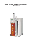
Milli-Q Synthesis and Milli-Q Synthesis A10
User Manual
Notice
The information in this document is subject to change without notice and should not be construed as a commitment
by Millipore Corporation. Millipore Corporation assumes no responsibility for any errors that might appear in this
document. This manual is believed to be complete and accurate at the time of publication. In no event shall
Millipore Corporation be liable for incidental or consequential damages in connection with or arising from the use of
this manual.
Copyright
PRINTED IN FRANCE.
ALL RIGHTS RESERVED.
ã 2002 MILLIPORE CORPORATION.
THIS BOOK OR PARTS THEREOF MAY NOT BE REPRODUCED IN ANY FORM WITHOUT THE WRITTEN
PERMISSION OF THE PUBLISHERS.
Rev. 0 - 06/02
Trademarks
Millipore is a registered trademark of Millipore Corporation.
Elix, Q-Gard, MilliPak and Milli-Q are registered trademarks of Millipore Corporation.
Quantum, RiOs and A10 are trademarks of Millipore Corporation.
Pyrogard is a registered trademark of Millipore Corporation.
Teflon is a registered trademark of E.I. du Pont de Nemours & Co.
Tygon is a registered trademark of the Norton Company.
ASTM is a registered trademark of the American Society for Testing and Materials.
Allen is a registered trademark of the Holo-Krome Technology Corporation.
Santoprene is a registered trademark of Advanced Elastomer Systems.
SLO-BLO is a registered trademark of Littlefuse, Inc.
Windows and EXCEL are registered trademarks of Microsoft Corporation.
All other trademarks are trademarks of their respective manufacturers.
Milli-Q Synthesis/Milli-Q Synthesis A10
Milli-Q Synthesis and Milli-Q Synthesis A10
230V version: European version
DECLARATION OF CONFORMITY
EUROPEAN UNION EC DIRECTIVES
Directive 89/336/CEE
Directive 73/23/CEE
¨ These Lab Water Systems are designed and manufactured in application of the following European Council
directives :
- 89/336/CEE relating to Electromagnetic compatibility.
- 73/23/CEE relating to electrical equipment designed for use within certain voltage limits.
¨ Standards to which conformity is declared as applicable are the following :
-
EN 55022 Classe B: 1998: Limits and method of radio-disturbance characteristics of
information technology equipment.
-
EN 50082-1: 1997: Electromagnetic compatibility: generic immunity standard.
-
EN 61000-3-2 : 1995 / A1 and A2 : 1998 / A14 : 2000 : Electromagnetic compatibility
(EMC) Part 3-2: limits : Limits for harmonic current emissions (equipment input current up to and
including 16A per phase )
-
EN 61000-3-3 : 1995 : Electromagnetic compatibility (EMC) Part 3: limits. Section 3 :
limitation of voltage fluctuation and flicker in low voltage supply systems for equipment with
rated current inferior or equal 6A.
-
EN 61010-1: 1993 /A2: 1995: Safety requirements for electrical equipment for
measurement, control, and laboratory use.
IT IS IMPORTANT TO READ THESE INSTRUCTIONS BEFORE USING THIS EQUIPMENT.
Protection insured by this device could be compromised in case of wrong use. Please follow the provided
information. It is highly recommended not to perform any work or maintenance to the internal parts or equipment of
the system. All internal maintenance or part replacements are to be solely performed by Millipore service
technicians.
Here is some additional information for technical reference.
Electrical specifications:
Milli-Q Synthesis: 230V, 50 Hz, 0.26 Amps
Milli-Q Synthesis A10: 230V, 50 Hz, 0.26 Amps
The rating and the specifications of all fuses used are listed in Chapter 9, Appendix 1 of this manual.
The system must be electrically connected to an earth grounded power supply.
In the event of any problems with this equipment, please do not hesitate to contact your local Millipore Service
Representative.
Milli-Q Synthesis/Milli-Q Synthesis A10
TABLE OF CONTENTS
CHAPTER 1
1-1
INTRODUCTION ........................................................................... 1
USING THIS MANUAL ..................................................................................................................1
Matching this manual with your Milli-Qâ ............................................................................................1
How to use the keypad and the LCD .................................................................................................1
Commonly used abbreviations in this manual ......................................................................................2
1-2
SAFETY INFORMATION ................................................................................................................3
1-3
CONTACTING MILLIPORE .............................................................................................................4
Telephone....................................................................................................................................4
Internet or Email ............................................................................................................................4
CHAPTER 2
2-1
PRODUCT INFORMATION ................................................................ 5
MILLI-Q PRODUCT WATER SPECIFICATIONS .......................................................................................5
Water produced by the Milli-Q Synthesis or Synthesis A10 ...................................................................5
Flowrate......................................................................................................................................................5
Resistivity.....................................................................................................................................................5
Particles ......................................................................................................................................................5
Pyrogens .....................................................................................................................................................5
TOC ..........................................................................................................................................................5
Micro-Organisms .........................................................................................................................................5
Comparison of Milli-Q Water and ASTM Standard Specifications ..........................................................5
2-2
SCHEMATIC OF MAIN COMPONENTS ..............................................................................................6
2-3
DESCRIPTION OF MAIN COMPONENTS .............................................................................................7
Inlet Solenoid Valve .......................................................................................................................7
Pressure Relief Valve.......................................................................................................................7
Pump ..........................................................................................................................................7
Q-Gard ......................................................................................................................................7
What are the different types of Q-Gards ?........................................................................................................7
When do I change the Q-Gard Purification Pack ?.............................................................................................8
UV Lamp......................................................................................................................................8
When do I change the UV Lamp ? ..................................................................................................................8
Quantum .....................................................................................................................................8
What are the different types of Quantum Cartridges ?.........................................................................................8
When do I change the Quantum Ultrapure Cartridge ? .......................................................................................8
Pyrogard 5000 UF Cartridge ..........................................................................................................9
Resistivity Sensor............................................................................................................................9
Resistivity and temperature measurements ..........................................................................................................9
Temperature Compensation / Conductivity Measurements ...................................................................................9
Resistivity/temperature measurements in agreement with USP 24 requirements.........................................................9
Milli-Q Synthesis/Synthesis A10
i
TABLE OF CONTENTS
Point Of Use Valve.........................................................................................................................9
MilliPak .....................................................................................................................................10
What types of MilliPak Filters are there ?........................................................................................................ 10
When do I change the MilliPak ? ................................................................................................................. 10
A10 TOC Monitor.......................................................................................................................12
What does the A10 do ?............................................................................................................................ 12
What maintenance is involved with the A10 ? ................................................................................................ 12
Does the A10 need to be calibrated ? .......................................................................................................... 12
TOC SUITABILITY TEST ............................................................................................................................... 12
2-4
TECHNICAL SPECIFICATIONS .......................................................................................................13
Dimensions (System and Clearance) ................................................................................................13
Weight .....................................................................................................................................13
Electrical....................................................................................................................................13
Measurement Ranges for TOC, Resistivity, Conductivity and Temperature................................................13
Materials of Construction ..............................................................................................................14
Noise Level ................................................................................................................................14
CHAPTER 3
PRE INSTALLATION ......................................................................15
3-1
PRE INSTALLATION CHECKLIST ......................................................................................................15
3-2
PRE INSTALLATION CHECKLIST – “ARMLESS” MILLI-QS ..........................................................................16
3-3
OPTIONAL EQUIPMENT YOU MAY NEED ..........................................................................................17
Wall Mounting Bracket.................................................................................................................17
Pressure Regulator........................................................................................................................17
Ball Valve for shutting off the feedwater supply ..................................................................................17
Remote Point Of Use Dispenser ......................................................................................................17
Remote Point Of Use Dispenser used on a “Production” type Milli-Q ......................................................18
Footswitch..................................................................................................................................18
Printer or Computer Cable.............................................................................................................18
Remote Display with Keypad .........................................................................................................18
“Explore Data” Software ...............................................................................................................18
3-4
INSTALLATION REQUIREMENTS ......................................................................................................20
Consumables needed for installation ...............................................................................................20
Space and Weight Requirements....................................................................................................20
Electrical Requirements..................................................................................................................20
Feedwater Requirements ...............................................................................................................21
Environmental Requirements ...........................................................................................................21
Other Requirements......................................................................................................................21
3-5
UNPACKING THE MILLI-Q BOX – WHAT’S INSIDE ? ............................................................................22
Milli-Q Synthesis/Synthesis A10
ii
TABLE OF CONTENTS
CHAPTER 4
4-1
INSTALLATION ........................................................................... 24
CONNECTING TO A SUPPLY OF FEEDWATER .....................................................................................24
Feedwater is from a reservoir .........................................................................................................24
Feedwater is from a pressurised source such as a pipe (a loop) ............................................................24
4-2
CONNECTION OF TUBING AND THE POWERCORD .............................................................................26
Feedwater Tubing........................................................................................................................26
Feedwater Pressure Relief Tubing ....................................................................................................26
UF Reject tubing ..........................................................................................................................26
Connecting the Power Cord ..........................................................................................................27
4-3
INSTALLATION OF THE Q-GARD....................................................................................................27
4-4
TURNING ON THE SYSTEM POWER ...............................................................................................30
4-5
INSTALLATION OF THE QUANTUM CARTRIDGE ...................................................................................30
4-6
INSTALLATION OF THE TYGON TUBING ...........................................................................................30
4-7
PURGING THE AIR FROM THE SYSTEM ..............................................................................................32
4-8
HYDRATING THE SYSTEM ............................................................................................................33
4-9
INSTALLATION AND RINSING OF THE MILLIPAK ...................................................................................35
4-10 HOW TO CALIBRATE THE FLOWRATE FROM THE MILLI-Q .......................................................................35
4-11 HOW TO CHANGE THE DISPLAYED LANGUAGE ..................................................................................38
4-12 HOW TO SHOW EITHER MW.CM OR mS/CM (RESISTIVITY OR CONDUCTIVITY UNITS) .....................................39
4-13 HOW TO SHOW NON TEMPERATURE COMPENSATED RESISTIVITY OR CONDUCTIVITY VALUES .............................41
What is temperature Compensation ? ............................................................................................................41
Why use non temperature compensated values ? .............................................................................................41
4-14 HOW TO SET THE DATE AND THE TIME OF DAY.................................................................................44
CHAPTER 5
USING THE MILLI-Q.................................................................... 46
5-1
HOW TO GET WATER FROM THE MILLI-Q ........................................................................................46
5-2
STANDBY, PRE OPERATE AND PRODUCT MODE .................................................................................48
What is STANDBY mode ? ..........................................................................................................................48
What is PRE OPERATE mode ? .....................................................................................................................48
What is PRODUCT mode ? ..........................................................................................................................48
5-3
HOW TO VIEW THE RESISTIVITY, TEMPERATURE AND TOC .....................................................................49
Viewing Resistivity........................................................................................................................49
Viewing Temperature ...................................................................................................................49
Viewing TOC .............................................................................................................................49
5-4
HOW TO USE THE FOOTSWITCH (OPTIONAL ACCESSORY).....................................................................50
5-5
HOW TO DISPENSE AN EXACT AMOUNT OF PRODUCT WATER ...............................................................50
5-6
HOW TO VIEW THE AGE OF THE CONSUMABLES ...............................................................................52
5-7
HOW TO UNDERSTAND MILLI-Q MESSAGES.....................................................................................54
Milli-Q Synthesis/Synthesis A10
iii
TABLE OF CONTENTS
CHAPTER 6
MAINTENANCE ...........................................................................57
6-1
MAINTENANCE SCHEDULE .........................................................................................................57
6-2
HOW TO REPLACE THE Q-GARD...................................................................................................58
6-3
HOW TO REPLACE THE QUANTUM CARTRIDGE ..................................................................................59
6-4
HOW TO REPLACE THE MILLIPAK ...................................................................................................64
6-5
HOW TO SANITISE AND CLEAN THE UF CARTRIDGE ............................................................................66
How often would I normally Sanitise and Clean the UF Cartridge ? .......................................................66
Things to know BEFORE you sanitise the UF Cartridge.........................................................................66
Sanitising and Cleaning the UF Cartridge.........................................................................................66
6-6
HOW TO CLEAN THE SCREEN FILTER ..............................................................................................70
6-7
HOW TO TIGHTEN THE POU DISPENSER ARM ..................................................................................71
6-8
HOW TO REPLACE THE A10 UV LAMP ...........................................................................................72
6-9
HOW TO CLEAN THE A10 TOC MONITORING DEVICE ......................................................................72
How long does the A10 Cleaning take ?....................................................................................................... 72
Why would I need to do an A10 Cleaning ? ................................................................................................. 72
Would an A10 Cleaning ever happen automatically ?..................................................................................... 72
How do I do an A10 Cleaning ? ................................................................................................................. 73
How do I cancel the A10 CLEANING once it is started ?................................................................................. 74
6-10 HOW TO CALIBRATE THE A10 TOC MONITORING DEVICE ..................................................................74
6-11 HOW TO PERFORM AN AIR PURGE ................................................................................................75
6-12 HOW TO REPLACE THE UV LAMP ..................................................................................................76
CHAPTER 7
TROUBLESHOOTING .....................................................................77
The problem is Low or No Flowrate from the POU Dispenser ................................................................77
The problem is Low Resistivity of the Product Water ............................................................................78
The problem is there is no power to the Milli-Q system........................................................................79
The problem is there is an “ERROR Number” Alarm displayed ..............................................................79
Continuation of “ERROR Number” Alarm displayed ............................................................................80
The problem is a message is displayed with a Flashing Service or Alarm LED ..........................................81
Other Troubleshooting items...........................................................................................................82
CHAPTER 8
ORDERING INFORMATION .............................................................83
8-1
CATALOGUE NUMBERS FOR CONSUMABLES ....................................................................................83
8-2
CATALOGUE NUMBERS FOR ACCESSORIES ......................................................................................84
8-3
CATALOGUE NUMBERS FOR ALL MILLI-QS ........................................................................................84
CHAPTER 9
APPENDIXES ...............................................................................85
APPENDIX 1
HOW TO REPLACE THE MAIN POWER FUSE .............................................................................85
APPENDIX 2
HOW TO TRANSFER INFORMATION TO A PRINTER .....................................................................86
Milli-Q Synthesis/Synthesis A10
iv
TABLE OF CONTENTS
Requirements needed ..................................................................................................................................87
What to do ...............................................................................................................................................87
What does the Printout look like ?..................................................................................................................88
APPENDIX 3
HOW TO TRANSFER INFORMATION TO A COMPUTER .................................................................89
Requirements needed ..................................................................................................................................89
How to do it..............................................................................................................................................89
APPENDIX 4
HOW TO USE A REMOTE DISPLAY ........................................................................................92
APPENDIX 5
HOW TO USE A REMOTE POU DISPENSER .............................................................................92
APPENDIX 6
COMP MODE 1 AND COMP MODE 2...........................................................................93
Milli-Q Synthesis/Synthesis A10
v
INTRODUCTION
Chapter 1
1-1
INTRODUCTION
USING THIS MANUAL
MATCHING THIS MANUAL WITH YOUR MILLI-Qâ
This manual is intended for use with a Millipore Milli-Q Synthesis or Milli-Q Synthesis A10 Water
Purification System.
This Owner’s Manual is a guide for use during the installation, normal operation and maintenance of a Milli-Q
Synthesis or Milli-Q Synthesis A10 Water Purification System. It is highly recommended to completely read this
manual and to fully comprehend its contents before attempting installation, normal operation or maintenance of the
Water Purification System.
You can easily identify your type of Water Purification System if you do not see the Catalogue Number. The Milli-Q
Synthesis and Synthesis A10 Water Purification Systems have an Orange Door on the front cabinet.
If this manual is not the correct one for your Water Purification System, then please contact Millipore.
HOW TO USE THE KEYPAD AND THE LCD
The Keypad and LCD (liquid crystal display) are located on the front of the Water System Cabinet.
The Keypad buttons sometimes have a slight delay when pressed. As an example, suppose you want to change the
Milli-Q from STANDBY mode to PRE OPERATE mode. This is done by pressing the OPERATE/STANDBY Keypad
button for about two seconds.
There are four Keypad buttons. These are labelled as OPERATE/STANDBY, MEASURE, CLEANING and MENU.
POWER
S T AND B Y
OPERATE / STANDBY
POWER
P RE
MEASURE
CLEANING
OP E RA T E
SERVICE
SERVICE
ALARM
ALARM
MENU
OPERATE / STANDBY
MEASURE
CLEANING
MENU
See the drawing above for their placement.
The LCD is a backlit, dual line 16-character display.
The LEDs are located to the right of the LCD (see above). The POWER LED is green. This is lit when the Water
System microprocessor has electrical power. The SERVICE LED is yellow. This will flash when a service type of LCD
message is displayed (i.e. EXCH. CARTRIDGES. is shown, meaning to change the cartridges in the system). The
ALARM LED is red. This will flash when an alarm condition is indicated on the LCD (i.e. PAK NOT IN PLACE,
meaning a purification pack is not fully in place or is absent).
Milli-Q Synthesis/Synthesis A10
1
INTRODUCTION
COMMONLY USED ABBREVIATIONS IN THIS MANUAL
This manual will use abbreviations for text that is commonly repeated (i.e. Liquid Crystal Display is abbreviated as
LCD).
The table below shows a list of the abbreviations used in this manual.
ABBREVIATION
mm
FULL TEXT
micron (unit of length)
mS/cm
microSiemens per centimeter (a measurement unit
describing the electrical conductivity of water)
A10ä
a Millipore device which measures TOC in
Ultrapure Water
ASTMÒ
American Society for Testing and Materials
CFU/ml
Colony Forming Units per millilitre
EDI
Eu/ml
Electrical Deionisation (referred to as ElixÒ also)
Endotoxin Units per millilitre
LCD
Liquid Crystal Display
LED
Light Emitting Diode
LPM
Litre Per Minute
MW.cm
MW.cm @ 25 °C
Megohm-centimeter
Megohm-centimeter when measured at 25 °C
mm
millimeter
NPT
National Pipe Thread (the type of thread used on
a fitting)
NPTF
National Pipe Thread Female
NPTM
National Pipe Thread Male
OD
Outer Diameter
ppb
part per billion; a microgram per litre (mg/L)
RO
Reverse Osmosis
SANIT.
TOC
Sanitisation
Total Organic Carbon
UF
Ultrafilter Cartridge
UV
Ultraviolet
Milli-Q Synthesis/Synthesis A10
2
INTRODUCTION
1-2
SAFETY INFORMATION
Your Milli-Q Water Purification System should be operated according to the instructions in this manual. In particular,
the hydraulic and electrical specifications should be followed and met. It is important to use this equipment as
specified in this manual; using this equipment in a different manner may impair the safety precautions of the Water
System.
THIS HAZARD symbol is used to
refer to instructions in this manual
that need to be done safely and
carefully
THIS ATTENTION symbol is used to
refer to instructions in this manual
that need to be done carefully
Milli-Q Synthesis/Synthesis A10
3
INTRODUCTION
1-3
CONTACTING MILLIPORE
TELEPHONE
AUSTRALIA
Tel. 1 800 222 111
or (02) 9888 8999
Fax (02) 9878 0788
AUSTRIA
Tel. (01) 877-8926
Fax (01) 877-1654
BALTIC COUNTRIES
Tel. +358 9 804 5110
Fax +358 9 256 5660
BELGIUM AND LUXEMBOURG
Tel. +32 2 726 88 40
Fax +32 2 726 98 84
BRAZIL
Tel. (011) 5548-7011
Fax (011) 5548-7923
CANADA
Tel. 1-800-645-5476
Fax 1-800-645-5439
CHINA, PEOPLE'S
REPUBLIC OF
Beijing:
Tel. (8610) 8519 1250
(8610) 6518 1058
Fax (8610) 8519 1255
Guangzhou:
Tel. (8620) 8755 4049
Fax (8620) 8752 0172
Hong Kong:
Tel. (852) 2803 9111
Fax (852) 2513 0313
Shanghai:
Tel. (8621) 5306 9100
Fax (8621) 5306 0838
CZECH REPUBLIC
Tel. 02-2051 3841
Fax 02-2051 4298
DENMARK
Tel. 70 10 00 23
Fax 70 10 13 14
EASTERN EUROPE, C.I.S.,
AFRICA, MIDDLE EAST
AND GULF
Life Sciences Division:
Tel. +33 3 88 38 9536
Fax +33 3 88 38 9539
BioPharmaceutical Division:
Tel. +43 1 877-8926
Fax +43 1 877-1654
Laboratory Water Division:
Tel. +33 1 30 12 7000
Fax +33 1 30 12 7180
FINLAND
Tel. (09) 804 5110
Fax (09) 256 5660
FRANCE
Tel. 01 30 12 7000
Fax 01 30 12 7180
GERMANY
Tel. (06196) 494-0
Fax (06196) 43901
HUNGARY
Tel. 1-205 9784
Fax 1-205 9792
INDIA
Tel. (91) 80-839 46 57
Fax (91) 80-839 63 45
IRELAND
Life Sciences and Laboratory
Water Divisions:
Tel. +44 1923 816375
Fax +44 1923 818297
BioPharmaceutical Division:
Tel. (021) 883 666
Fax (021) 883 048
ITALY
Vimodrone (Milano):
Tel. (02) 25.07.81
Fax (02) 26.50.324
Roma:
Tel. (06) 52.03.600
Fax (06) 52.95.735
JAPAN
Tel. (03) 5442-9711
Fax (03) 54429736 Life Sciences
9737 BioPharm.
9734 Lab Water
KOREA
Tel. (822) 551-0990
Fax (822) 551-0228
MALAYSIA
Tel. 603-757 1322
Fax 603-757 1711
MEXICO
Tel. (525) 576-9688
Fax (525) 576-8706
THE NETHERLANDS
Tel. 076-5022000
Fax 076-5022436
NORWAY
Tel. 22 67 82 53
Fax 22 66 04 60
POLAND
Tel. 22-669 12 25
22-663 70 31
Fax 22-663 70 33
PUERTO RICO
Tel. (787) 273-8495
Fax (787) 747-6553
SINGAPORE
Tel. (65) 842 1822
Fax (65) 842 4988
SPAIN AND PORTUGAL
Tel. +34 917 283 960
Fax +34 917 292 909
SWEDEN
Tel. 08-628 6960
Fax 08-628 6457
SWITZERLAND
Volketswil:
Tel. (01) 908-30-60
Fax (01) 908-30-80
Lausanne:
Tel. (021) 641 2550
Fax (021) 641 2551
TAIWAN
Taipei:
Tel. (886-2) 700-1742
Fax (886-2) 755-3267
Hsin Chu City:
Tel. (886-3) 571-0178
Fax (886-3) 572-9520
U.K.
Tel. 01923 816375
Fax 01923 818297
U.S.A.
Tel. (781) 533-6000
Fax (781) 533-3110
IN ALL OTHER COUNTRIES
Millipore Intertech (U.S.A.)
Tel. +1 (781) 533-8622
Fax +1 (781) 533-8630
Phone numbers may change. See Millipore’s Internet site at www.millipore.com for updated information.
INTERNET OR EMAIL
Internet Site Address:
www.millipore.com
Email:
[email protected]
www.millipore.com/techservice
Milli-Q Synthesis/Synthesis A10
4
PRODUCT INFORMATION
Chapter 2
2-1
PRODUCT INFORMATION
MILLI-Q PRODUCT WATER SPECIFICATIONS
WATER PRODUCED BY THE MILLI-Q SYNTHESIS OR SYNTHESIS A10
FLOWRATE
TOC
â
0.8 - 1.2 LPM with MilliPak Express 20
RESISTIVITY
minimum 18.0 MW.cm @ 25 °C
typically 18.2 MW.cm @ 25 °C
PARTICLES
£ 1/ml (particle size > 0.22 mm)
maximum 5 ppb (this specification came from test
conditions where a Milli-Q Synthesis was fitted with a
Q-Gardâ 1 Purification Pack and a Quantumä EX
Ultrapure Cartridge and the feedwater came from a
Millipore RiOsä Water System. The feedwater TOC
value was < 50 ppb). The TOC of the Milli-Q
Product Water can vary as a function of the
feedwater TOC.
MICRO-ORGANISMS
PYROGENS
£ 1 CFU/ml
< 0.001 Eu/ml
COMPARISON OF MILLI-Q WATER AND ASTM STANDARD SPECIFICATIONS
Milli-Q Product Water Quality will meet or exceed ASTM Type I Standard Specifications for Reagent Grade Water.
The specifications for ASTM Type I Reagent Grade Water are shown below. Note that the Water Quality
Specifications for a Milli-Q Synthesis (or Milli-Q Synthesis A10) are listed in the section just above.
(From “Standard Specification for Reagent Water” Designation: D 1193 – 99; American Society For Testing And
Materials)
ASTM Type I Standard Specifications for Reagent Grade Water
Parameter
Value
Conductivity @ 25 °C (mS/cm)
0.056
Resistivity @ 25 °C (MW.cm)
18
Total Silica max. value (mg/L)
3
Total Organic Carbon max. value (mg/L)
100
Chlorides max. value (mg/L)
1
Sodium max. value (mg/L)
1
pH
not specified (The measurement of pH has been
eliminated for this standard because this grade of
water does not contain constituents in sufficient
quantity to alter pH)
Milli-Q Synthesis/Synthesis A10
5
PRODUCT INFORMATION
2-2
SCHEMATIC OF MAIN COMPONENTS
The water flow through a Milli-Q Synthesis Water Purification System is shown here in a flow diagram. A
description of each item is in the next section below.
RECIRCULATED
WATER PATH
FEEDWATER
A
MILLI-Q
PRODUCT
WATER
G
B
D
E
H
I
F
C
PRESSURE RELIEF
UF DRAIN
The water flow through a Milli-Q Synthesis A10 is shown here in a flow diagram.
RECIRCULATED
WATER PATH
FEEDWATER
A
G
B
D
E
MILLI-Q
PRODUCT
WATER
H
I
F
C
PRESSURE
RELIEF
UF DRAIN
A-10 TOC MONITOR
A-10 REJECT
WATER PATH
Identification of lettered items in the flow schematic above
A
Inlet Solenoid
Valve
D
UV Lamp and
Housing
G
Resistivity
Sensor
B
Pump
E
Quantum
Ultrapure
Cartridge
H
Electric 2-way
Valve
C
Q-Gard
Purification
Pack
F
PyrogardÒ
5000 UF
Cartridge
I
MilliPak
Membrane
Filter
Milli-Q Synthesis/Synthesis A10
6
PRODUCT INFORMATION
2-3
DESCRIPTION OF MAIN COMPONENTS
INLET SOLENOID VALVE
The Inlet Solenoid Valve is used to control the flow of feedwater into the Milli-Q system. The Inlet Solenoid Valve is
open when the system is delivering water from the Point Of Use Dispenser and during Recirculation mode.
PRESSURE RELIEF VALVE
The Milli-Q system has a Feedwater Pressure Relief Valve inside. The purpose of this is to vent out any Feedwater
that has a pressure higher than 0.75 bar (11 psi). This would prevent any excessive Feedwater pressure that could
build up in the Milli-Q system during Recirculation Mode.
A piece of tubing is included in the Accessories Bag. This tubing is attached to the Milli-Q system and than placed
in a drain or sink. When the incoming Feedwater has a pressure greater than 0.75 bar, the Pressure Relief Valve
will open up and Feedwater will be vented to drain via the attached tubing. The water will stop flowing to drain
when the Feedwater Pressure drops to less than 0.75 bar. If a Pressure Regulator is installed on the Feedwater
Tubing (between the Milli-Q and a Loop), then it is unlikely that the Feedwater Pressure will get this high.
The installation of this tubing is described in more detail in Chapter 4 (Installation).
A Milli-Q fed from a Reservoir will not need the Pressure Relief Valve tubing. A Milli-Q fed from a Pressurised Pipe
(a Loop) should have the Pressure Relief Valve tubing installed during installation. Please note that the Pressure Relief
Valve is factory installed inside all Milli-Q systems and only the tubing needs to be attached during installation.
PUMP
The pump is used to bring water into the Milli-Q and then to send it through the various components such as the QGard Purification Pack and the Quantum Ultrapure Cartridge.
Q-GARD
The Q-Gard Purification Pack is used to remove ions and organic molecules from the feedwater. The Q-Gard is a
consumable device. A consumable device is something that is periodically changed out for a new one during the
maintenance of the Water System.
WHAT ARE THE DIFFERENT TYPES OF Q-GARDS ?
The Q-Gard 1 is used when the feedwater comes from RO, distillation or Electrodeionisation (EDI). An example of
RO or EDI feedwater is the water coming from either a Millipore RiOs or Elix Water Purification System. This type of
feedwater typically has some ions but contains little organic, particulate and colloidal contamination.
The Millipore Catalogue Number for a Q-Gard 1 is QGARD00R1. See Section 8-1 for more information.
The Q-Gard 2 is used whenever the feedwater comes from a source other than those mentioned above. An
example of feedwater requiring a Q-Gard 2 would be Service Deionised Water (this is the process of deionising
water by connecting bottles of ion exchange directly to tap water and deionising the tap water). Deionised Water
produced by multiple regeneration ion exchange resins may have a high level of organic, particulate and colloidal
contamination.
The Millipore Catalogue Number for a Q-Gard 2 is QGARD00D2. See Section 8-1 for more information.
Milli-Q Synthesis/Synthesis A10
7
PRODUCT INFORMATION
WHEN DO I
CHANGE THE
Q-GARD PURIFICATION PACK ?
The decision to change a Q-Gard Pack is based upon time (calendar days) with a Milli-Q Synthesis system.
The Milli-Q Synthesis will indicate a message “EXCH. CARTRIDGES” after 180 Calendar Days.
The Milli-Q Synthesis A10 will never display a message “EXCH. CARTRIDGES”. It is up to the user to change the
Q-Gard, Quantum and MilliPak based upon resistivity (and TOC) values.
UV LAMP
The dual wavelength UV Lamp emits light at 185 nm (for TOC reduction) and 254 nm (Germicidal action). The UV
Lamp is used to kill bacteria and to reduce the levels of organic molecules in the water stream between the Q-Gard
Pack and the Quantum Cartridge. The UV Lamp has a Millipore Catalogue Number of ZMQUVLP01.
WHEN DO I
CHANGE THE
UV LAMP ?
It is recommended to change the UV Lamp every 365 Days (once per year). The Milli-Q LCD will show a message
“EXCHANGE UV” after 365 Calendar Days indicating it is time to replace the UV Lamp.
QUANTUM
The Quantum Ultrapure Cartridge is used to remove trace levels of ions and organic molecules.
WHAT ARE THE DIFFERENT TYPES OF QUANTUM CARTRIDGES ?
The Quantum IX contains only Mixed Bed Ion Exchange resin. This type of Quantum Cartridge is used when
maintaining absolutely trace levels of ions is critical.
The Millipore Catalogue Number for a Quantum IX is QTUM000IX.
information.
See Section 8-1 for more
The Quantum EX contains ion exchange resin and synthetic carbon. These purification media are used when the
Milli-Q Product Water needs to have both trace levels of ions and trace levels of organic species.
The Millipore Catalogue Number for a Quantum EX is QTUM000EX. See Section 8-1 for more
information.
The Quantum VX contains media that removes Volatile Organic Carbon species and maintains trace levels of
ions.
The Millipore Catalogue Number for a Quantum VX is QTUM000VX. See Section 8-1 for more
information.
WHEN DO I
CHANGE THE
QUANTUM ULTRAPURE CARTRIDGE ?
It is recommended to change the Quantum Ultrapure Cartridge when the Q-Gard Purification Pack
is changed. See “When do I change the Q-Gard Purification Pack” (see the section above) for more
information.
Milli-Q Synthesis/Synthesis A10
8
PRODUCT INFORMATION
PYROGARD 5000 UF CARTRIDGE
The Pyrogard 5000 UF Cartridge (called UF Cartridge in the remainder of this manual) is used to remove any
Pyrogens or Endotoxins in the Milli-Q Product Water. The UF Cartridge will also remove bacteria from the water
passing through it.
The maintenance of the UF Cartridge involves sanitising and cleaning it every 4 weeks with Sodium Hydroxide. The
Sanitisation of the UF Cartridge is described in the Maintenance Chapter of this manual.
The UF Cartridge has a Reject Water Stream which is plumbed via a piece of 8 mm OD tubing from the back of the
Milli-Q to a sink or a drain. This stream is used to transport the bacteria, pyrogens, particles, ... that are rejected by
the UF Cartridge. The flow through this piece of tubing is controlled by a solenoid valve. This valve is only open for
30 seconds every 3 hours of PRE OPERATE mode or when the AIR PURGE mode is active. This valve will also open
for portions of the Sanitisation Mode.
RESISTIVITY SENSOR
RESISTIVITY AND TEMPERATURE MEASUREMENTS
The resistivity sensor is used to measure the electrical resistivity of the Milli-Q Product Water. Additionally, a
thermistor (temperature sensor) is located in the resistivity sensor. The temperature displayed on the Milli-Q LCD
during PRODUCT mode is measured by this thermistor.
TEMPERATURE COMPENSATION / CONDUCTIVITY MEASUREMENTS
The resistivity and temperature are measured while water is flowing through the sensor. The Milli-Q microprocessor
will then temperature compensate the resistivity to a 25 °C value. It is possible to use the Milli-Q software to display
non-temperature compensated resistivity. It is also possible to display conductivity (mS/cm) (temp. compensated or
non-temp. compensated) on the LCD by using the Milli-Q software. The software can be changed by using the
Keypad.
RESISTIVITY VERIFICATION ACCORDING TO USP 24 <645>
A Millipore Field Service Representative can perform resistivity and temperature measurement verification of your
Milli-Q system.
Contact Millipore for more information regarding resistivity and temperature measurement verification in accordance
with USP 24 specifications.
POINT OF USE VALVE
The Point Of Use (POU) Dispenser has a 2-way electric valve inside.
This valve is closed when the POU Dispenser Trigger is in the upright position. This also places the Milli-Q into PRE
OPERATE mode after 90 seconds if you were using the Milli-Q in PRODUCT mode.
When the POU Dispenser Trigger is pushed down, the electric valve is powered. This allows water to be dispensed
out of the Milli-Q System instead of being recirculated back to the pump (see flow diagram).
Milli-Q Synthesis/Synthesis A10
9
PRODUCT INFORMATION
MILLIPAK
The MilliPak End Filter is a membrane based filter that removes all particles and bacteria with a size greater than
0.22 mm by a sieving mechanism. All contaminants larger than the filter pore size are retained on its surface. This
essentially will block and retain any bacteria present in the water flowing through it.
WHAT TYPES OF MILLIPAK FILTERS ARE THERE ?
There are 2 types of MilliPak Filters (sometimes called the Final Filter).
The Sterile MilliPak 40 is generally used for some Life Science applications. This has a Millipore
Catalogue Number of MPGL04SK2. See Section 8-1 for more information.
The Non Sterile MilliPak Express 20 is generally used for Analytical Science Applications including
applications where trace levels of Volatile Organic Compounds are desired or with Life Science
Applications where Endocrine Disrupter Analysis is being done. The Non Sterile MilliPak Express 20
has a Millipore Catalogue Number of MPGP02001. See Section 8-1 for more information.
WHEN DO I
CHANGE THE
MILLIPAK ?
The MilliPak is changed when the Q-Gard Purification Pack and the Quantum Ultrapure Cartridge are changed.
However, it may be necessary to change the MilliPak if it becomes clogged with particles or bacteria and reduces
the flowrate of Milli-Q Product Water.
Milli-Q Synthesis/Synthesis A10
10
PRODUCT INFORMATION
Q-GARD
QUANTUM
MILLIPAK
Milli-Q Synthesis/Synthesis A10
11
PRODUCT INFORMATION
A10 TOC MONITOR
WHAT DOES THE A10
DO
?
The A10 TOC Monitor (called A10 in this manual) is used to measure the TOC of the Milli-Q Product Water. The
A10 is located inside the Milli-Q System Cabinet. Any Milli-Q system with an A10 inside will have ‘A10’
on the end of the name of the Milli-Q (i.e. Milli-Q Synthesis A10 vs. Milli-Q Synthesis).
An A10 TOC measurement is initiated every time the Milli-Q is brought from PRE OPERATE to PRODUCT mode
(when the POU Dispenser Trigger is brought forward). A single TOC Measurement will take approximately
5 minutes. It is possible to have a TOC analysis time of either 9 or 12 minutes when the TOC levels are high. The
A10 will continuously perform TOC measurements while the Milli-Q is in PRODUCT mode. The A10 will perform a
TOC measurement once per hour while the Milli-Q is in PRE OPERATE mode. The A10 will not perform any TOC
measurements when the Milli-Q is in STANDBY mode.
WHAT MAINTENANCE IS INVOLVED WITH THE A10 ?
The A10 uses a small UV light during its TOC analysis mode. The A10 UV Lamp needs to be replaced
periodically. The normal useful lifetime of the A10 UV Lamp is 1 year. The Milli-Q system uses a calendar day
timer to record the age of the A10 UV Lamp.
A service message is prompted after 365 Days
(“EXCHANGE A10 UV”) to remind you to change the A10 UV Lamp. The Catalogue Number for the A10 UV
Lamp is ZFA10UV01.
There is a Cleaning Mode for the A10. This Cleaning Mode can be initiated with the Milli-Q software. The
A10 Cleaning mode does not use a chemical reagent of any kind. The A10 Cleaning is explained in further detail
in the Maintenance Section of this manual.
DOES THE A10
NEED TO BE CALIBRATED
?
It is recommended to calibrate the A10 once per year. The A10 can not be calibrated “on-site” – it needs to be
calibrated by Millipore. The accuracy claims of the TOC measurement are valid for 1 year from calibration. The
A10 UV Lamp is replaced as part of the calibration procedure.
An annual verification can be performed instead of a complete calibration depending on your requirements.
Contact Millipore for further information regarding a calibration or verification of the A10 TOC
Monitor Device.
TOC SUITABILITY TEST ACCORDING TO USP 24 <643>
It is possible to perform a TOC Suitability Test with the A10 TOC Monitor.
Contact Millipore for further information on how to perform a TOC Suitability Test with an A10 TOC
Monitor.
Milli-Q Synthesis/Synthesis A10
12
PRODUCT INFORMATION
2-4
TECHNICAL SPECIFICATIONS
DIMENSIONS (SYSTEM AND CLEARANCE)
The height, width and depth of a Milli-Q Synthesis (and Synthesis A10) are shown here:
256 mm
190 mm
336 mm
74 mm
20 mm
445 mm
296 mm
778 mm
WEIGHT
§
Milli-Q Synthesis:
Operating weight (wetted Q-Gard, Quantum and MilliPak): 16 kg.
§
Milli-Q Synthesis A10:
Operating weight: 16.8 kg.
ELECTRICAL
§
The electrical requirements for a Milli-Q Synthesis (or Milli-Q Synthesis A10) are:
120 VAC ± 10%, 50/60 Hz. 0.5 amp source, 2 amp SLO BLOÒ fuse used
230 VAC ± 10%, 50/60 Hz. 0.26 amp source, 1 amp SLO BLO fuse used
§
The source of electrical power should be within 1 meter of the Milli-Q. The source of electrical power must be
earth grounded.
MEASUREMENT RANGES FOR TOC, RESISTIVITY, CONDUCTIVITY AND TEMPERATURE
The Milli-Q can display various Product Water quality parameters. The range of measurement of each parameter is
written below.
Resistivity Measurement Range:
2.4 – 18.2 MW.cm (compensated to 25 °C values)
Conductivity Measurement Range:
0.055 – 0.294 mS/cm
Temperature Measurement Range:
0 – 45 °C (not the system temperature operating range)
TOC Measurement Range:
1 – 999 ppb
Milli-Q Synthesis/Synthesis A10
13
PRODUCT INFORMATION
MATERIALS OF CONSTRUCTION
The compositions of the components that contact water are shown in the table below.
Component
Material of Construction
Check Valve
PE, EPDM, Stainless Steel
Fittings
Inlet Solenoid Valve
Manifold
PE, PA, PVDF
Stainless Steel, POM, NBR
PPO
PE = Polyethylene
PA = Polyamide
PVDF = Polyvinylidene Fluoride
MilliPak 40
PC Housing, PVDF
Membrane
EPDM = Ethylene Propylene
Terpolymer Rubber
MilliPak Express 20
SAN Housing, PES
Membrane
ABS = Poly(Acrylonitrile
Butadiene Styrene)
O-rings
Pack Adapter (where Q-Gard
plugs in)
EPDM
ABS
POM = Polyoxymethylene
NBR = Nitrile Rubber
(Acrylonitrile-Butadiene Rubber)
POU Valve
POM, NBR Seal, Stainless
Steel, PTFE
Pump
Diaphragm =
SantopreneÒ/PTFE, Valves
= EPDM
PP = Polypropylene
PP (tubes), PE (endcaps),
EPDM O-rings
SAN = Poly(Styrene Acrylonitrile)
Q-Gard Pack
Quantum Cartridge
Polypropylene (tube +
endcaps), EPDM O-rings
Resistivity Cell
Stainless Steel
Screen Filter
Stainless Steel
Tubing
Tubing Inserts
UF Cartridge Membrane
UF Cartridge Housing
UV Lamp
UV Lamp Housing
PC = Polycarbonate
PTFE = Polytetrafluoroethylene
PES = Polyethersulfone
PPO = Polyphenylene Oxide
PE
Rubber O-ring, stainless
steel collar, PA insert
Polysulphone
ABS
Ultrapure Quartz Glass
316 Stainless Steel
NOISE LEVEL
The Milli-Q has a noise level of 42 dB at a distance of 1 meter away.
Milli-Q Synthesis/Synthesis A10
14
PRE INSTALLATION
Chapter 3
3-1
PRE INSTALLATION
PRE INSTALLATION CHECKLIST
The installation of your Milli-Q will go much easier if certain pre installation requirements are met and followed.
The checklist below can be used to facilitate the pre installation of your Milli-Q system. You can refer back to this
checklist as you read the sections on Optional Equipment, Installation Requirements and Unpacking the Milli-Q Box.
q
Do you have a Q-Gard Purification Pack ?
q
Do you have a Quantum Ultrapure Cartridge ?
q
Do you have a MilliPak ?
q
Do you have a Milli-Q and all items in its Accessories Bag?
q
Do you have a source of electrical power close enough to the Milli-Q ?
q
Is the electrical source earth grounded ?
q
Are you feeding with a Reservoir ? (if feeding from a pressurised pipe, see below)
q
q
q
Is the reservoir full of water ?
q
Is the source of water filling the reservoir fully operational ?
q
Does the reservoir have an 8 mm tubing connection on one of its valves ?
Are you feeding the Milli-Q from a pressurised pipe (loop) ?
q
Do you have a pressure regulator ready to connect between the pipe and the Milli-Q ?
q
Is the water system feeding the pipe fully operational ?
q
Does the pipe have a valve ending with a 1/2 inch NPTM connection ? If not, do you have a fitting or
connection that will attach to the pipe and will end in a 1/2 inch NPTM connection?
q
Is there a way to shut off water from the pipe to the Milli-Q ? If not, did you order a ball valve from
Millipore to install on the Feedwater Tubing ?
Are you mounting the Milli-Q on a wall ?
q
A wall mounting bracket may be needed in specific conditions
q
Will the wall support the weight of the Milli-Q (plus full reservoir, ...) ?
q
Is the Milli-Q accessible at this height (viewing the LCD, using the keypad) ?
q
Did you include space on the right side of the Milli-Q to remove and replace the Q-Gard ?
q
Did you want a location so as to dispense water over a sink ?
q
Is the Milli-Q located within 2.5 meters of a drain (for the UF Reject tubing) ?
q
Is the Milli-Q located within 2.5 meters of a drain (for the Feedwater Pressure Relief Valve tubing) ?
q
Are the room environmental conditions adequate (humidity, temperature) ?
q
If you are going to connect a printer or computer to the Milli-Q later, did you leave room for this ?
q
If you are using a footswitch accessory to control the Milli-Q, did you leave room for this ?
Milli-Q Synthesis/Synthesis A10
15
PRE INSTALLATION
3-2
PRE INSTALLATION CHECKLIST – “ARMLESS” MILLI-Q
Milli-Q Systems can be ordered from Millipore without the Front Arm and without the Front Point Of Use Dispenser.
These are called “Production” or “Armless” Milli-Q Systems. These Milli-Q Systems always begin with ZMQP
instead of ZMQS.
When a “Production” Milli-Q is ordered (you ordered Millipore Catalogue Number ZMQP ... for example), the
Milli-Q arrives in a box without a Front Arm and without a Front Point Of Use Dispenser.
It is necessary to have a Remote Point Of Use Dispenser with these types of Milli-Qs. Section 3-3 of this manual has
more information regarding the Remote Point Of Use Dispenser.
It may be desired to have Remote Display with the “Production” Milli-Q System. An example of when this would be
needed is when the Milli-Q System is being mounted underneath a Lab Bench. In this instance, the Remote Display
(and Remote Point Of Use Dispenser) could be mounted on top of the Lab Bench.
When you have a “Production” type of Milli-Q System, use the same Pre Installation Checklist on the
previous page. Additionally, you should review the items below also.
q
Do you have a Remote Point Of Use Dispenser (this item is not part of a ZMQP Millipore Catalogue Number) ?
q
Do you have a Remote Display ? (this item is not part of a ZMQP Millipore Catalogue Number) ?
q
Will the Milli-Q System Cabinet and the Remote POU Dispenser be located within 2.5 meters of each other?
q
Will the Milli-Q System Cabinet and the Remote Display be located within 2.4 meters of each other?
Milli-Q Synthesis/Synthesis A10
16
PRE INSTALLATION
3-3
OPTIONAL EQUIPMENT YOU MAY NEED
WALL MOUNTING BRACKET
The Millipore Catalogue Number for the Wall Mounting Bracket is SYSTFIX01. The mounting hardware
for attaching the bracket to a wall is not included and must be supplied. The bracket is attached with at least 2
bolts (or screws).
Width of bracket = 23 cm
Height of bracket = 5.4 cm
Thickness of bracket = 0.4 cm
Diameter of holes in the bracket for bolts or screws = 0.7 cm
Mounting holes on bracket are approximately 5.4 cm from either edge
PRESSURE REGULATOR
The Millipore Catalogue Number for a Pressure Regulator (with Pressure Gauge and 8 mm tubing connections) is
ZFMQ000PR.
ATTENTION
It is important that the Pressure Regulator is adjusted while water is
flowing through it. A range between 0.1 bar and 0.3 bar (1.5 to
4.5 psi) is the normal setting of the Pressure Regulator while water
is being dispensed from the Milli-Q. The Pressure Regulator is
factory pre-set to 0.3 bar while water at 80 LPH is flowing through
it.
BALL VALVE FOR SHUTTING OFF THE FEEDWATER SUPPLY
It is highly recommended to use a ball valve on the Feedwater Tubing. The Ball Valve will be used to shut off the
Feedwater Supply if necessary.
Contact Millipore for information regarding the Ball Valve. It is usually necessary to have fittings installed on both
ends of the Ball Valve to be able to connect it to the Feedwater Tubing.
REMOTE POINT OF USE DISPENSER
A Remote POU Dispenser can be added to the Milli-Q. This allows you to dispense water a maximum distance of
2.5 meters away from the Milli-Q. The Remote POU Dispenser is rested on a moveable arm that allows 180°
rotation.
The Millipore Catalogue Number for a Remote POU Dispenser (plus arm and weighted base) is
ZMQSP0UR1. It is also necessary to order an installation kit with the Remote POU Dispenser. This
Installation Kit has a Millipore Catalogue Number of ZMQSP0U01.
The Remote POU Dispenser can be either wall mounted or set on a benchtop. The Installation Instructions for the
Remote POU Dispenser are included with it.
Milli-Q Synthesis/Synthesis A10
17
PRE INSTALLATION
REMOTE POINT OF USE DISPENSER USED ON A “PRODUCTION”
TYPE MILLI-Q
A “Production” type Milli-Q System needs to have a Remote Point Of Use Dispenser added to it. Without one, you
would not be able to dispense water from the Milli-Q.
All of the information in the above section (“Remote Point Of Use Dispenser”) applies to a “Production” type of
Milli-Q System. You will not need to order the Installation Kit however. The items in the Installation Kit are Factory
installed on “Production” Milli-Q Systems.
ATTENTION
Do not order Installation Kit Catalogue Number ZMQSP0U01 when
you have a Milli-Q System beginning with a ZMQP Catalogue
Number.
FOOTSWITCH
The Millipore Catalogue Number for the Footswitch (plus cable) is ZMQSFTS01. The Footswitch allows
you a ‘hands free’ operation where you could change the Milli-Q from PRE OPERATE mode to PRODUCT mode.
The length of the Footswitch Cable is 5 meters. You will use about 0.3 meters of the Footswitch Cable inside the
Milli-Q.
PRINTER OR COMPUTER CABLE
The Millipore Catalogue Number for the Printer Cable is PRNTCBL01. Its length is 2.79 meters.
The Millipore Catalogue Number for the Computer Cable is C0MPCBL01. Its length is 1.65 meters.
You will use about 0.6 meters of either cable for its connection inside the Milli-Q cabinet.
REMOTE DISPLAY WITH KEYPAD
The Millipore Catalogue Number for a Remote Display is ZMQSRMDS1. The Remote Display allows you
to view the LCD and to use the Keypad Buttons remotely.
The dimensions of the Remote Display are length = 204 mm, height = 112 mm and depth = 48 mm. Its weight is
613 g.
The Remote Display comes with a 3 meter cable that plugs into the Milli-Q System inside. You will use about
0.6 meters of the cable inside the Milli-Q.
The Remote Display can be wall mounted. There are 2 Stainless Steel Brackets that are attached to either side of
the Remote Display. These brackets can be fastened to the wall. The Hardware necessary to attach these brackets
to a wall (i.e. screws, bolts) does not come with the Remote Display.
The instructions for installing the Remote Display are inside its shipping box. The instructions for installing a Remote
Display are not inside this manual. Contact Millipore for these instructions if you would like to see them before
obtaining the Remote Display.
“EXPLORE DATA” SOFTWARE
It is possible to download data from the Milli-Q to a computer. The data can be graphed and presented on the
computer. An example of this would be to display the resistivity of the Milli-Q Product Water for the last 20 days.
Millipore sells, as an accessory (not supplied with the Milli-Q), software that can used to download data from the
Milli-Q. This software can then be used to process the data in different ways.
The Millipore Catalogue Number for the “Explore Data” Software is S0FT000A1.
You will also need a computer cable to be used between the Milli-Q and a computer. This cable is not supplied
with the software or with the Milli-Q. The Millipore Catalogue Number for this cable is C0MPCBL01. See the
Section above labelled “Printer or Computer Cable” for more information.
Milli-Q Synthesis/Synthesis A10
18
PRE INSTALLATION
FOOTSWITCH
WALL MOUNTING BRACKET
BALL VALVE
PRESSURE REGULATOR
REMOTE DISPLAY
REMOTE POU DISPENSER
Milli-Q Synthesis/Synthesis A10
19
PRE INSTALLATION
3-4
INSTALLATION REQUIREMENTS
CONSUMABLES NEEDED FOR INSTALLATION
You will need one Q-Gard Pack, Quantum Cartridge and MilliPak for installation. These items do not come with
the Milli-Q system. These items need to be ordered separately. The Catalogue Numbers and options for these
items are written below.
Some of the items below can be ordered as part of a kit. An example might be a kit consisting of a particular type
of Quantum Cartridge plus a MilliPak Express 20. See Chapter 8, Section 8-1 for the catalogue numbers and
descriptions of various kits.
See Section 2-3 for technical information regarding the Consumables for a Milli-Q system.
Q-Gard Purification Pack
Þ
Q-Gard 1
QGARD00R1
1/box (RO,Elix,distilled,Milli-RX,Milli-RO feedwater)
Þ
Q-Gard 2
QGARD00D2
1/box (DI, Service DI feedwater)
Quantum Ultrapure Cartridge
Þ
Quantum IX
QTUM000IX
1/box (100% Ion Exchange Resin)
Þ
Quantum EX
QTUM000EX
1/box (Ion Exchange Resin + media for Organics removal)
Þ
Quantum VX
QTUM000VX
1/box (Volatile Organics removal + ion exchange resin)
Quantum Ultrapure Cartridge with 1 non sterile MilliPak 20 Express
Þ
Quantum IX
QTUMMPEIX
1/box
Þ
Quantum EX
QTUMMPEEX
1/box
MilliPak 40 Final Filter
Þ
MilliPak 40 (sterile) MPGL04SK2
2/box
MilliPak Express 20 Final Filter
Þ
MilliPak Express 20 (non sterile)
MPGP02001
1/box
SPACE AND WEIGHT REQUIREMENTS
See Section 2-4 for a drawing showing the dimensions of a Milli-Q.
§
Total Height needed (includes POU Dispenser being fully upright):
53 cm
§
Total Width needed (includes room needed to remove Q-Gard):
45 cm
§
Total Depth needed (includes POU when it is fully upright):
53 cm
§
Operating weight for a ‘wet’ Milli-Q Synthesis (Synthesis A10):
16 kg (16.8 kg)
ELECTRICAL REQUIREMENTS
§
The electrical requirements for a Milli-Q Synthesis (or Milli-Q Synthesis A10) are:
120 VAC ± 10%, 50/60 Hz. 0.5 amp source, 2 amp SLO BLO fuse used
230 VAC ± 10%, 50/60 Hz. 0.26 amp source, 1 amp SLO BLO fuse used
§
The source of electrical power should be within 1 meter of the Milli-Q. The source of electrical power must be
earth grounded.
Milli-Q Synthesis/Synthesis A10
20
PRE INSTALLATION
FEEDWATER REQUIREMENTS
Feedwater Conductivity:
< 100 mS/cm @ 25 °C
Feedwater Flowrate:
The source of feedwater should deliver ³ 1.5 LPM
Maximum Feedwater Pressure:
£ 0.3 bar (use a Pressure Regulator if necessary)
Minimum Feedwater Pressure:
³ 0.1 bar (i.e. reservoir Û same level as the Milli-Q)
Feedwater temperature:
Between 5 °C and 35 °C
Items to note about feedwater:
§
The ion exchange capacity of the Q-Gard Purification Pack and the Quantum Ultrapure Cartridge are a strong
function of the conductivity and the dissolved CO2 gas level of the Feedwater Source.
§
The Fouling Index (Silt Density Index) of the Feedwater, when > 5, can effect the ability of the Ion Exchange
Resin to remove ions.
§
The TOC level of the Milli-Q Product Water could be affected by the type of feedwater.
Contact Millipore for additional information regarding the 3 items noted just above.
It is highly recommended to use a feedwater source treated by RO or EDI. Millipore RiOs or Elix Water Purification
Systems are examples of RO or EDI feedwater sources respectively.
ENVIRONMENTAL REQUIREMENTS
Ambient Storage Temperature of the Milli-Q:
Between 5 °C and 40 °C
Ambient Operating Temperature (air temp):
Between 5 °C and 25 °C
Relative Humidity
Between 20% and 80% without condensation
Operating Altitude
Less than 2000 Meters
OTHER REQUIREMENTS
Reservoir is the feedwater source
If you are using a reservoir as the feedwater source, then you will need a ball valve on the reservoir. This ball valve
is normally supplied on the standard Millipore 30 L or 60 L or 100 L Reservoirs.
The end of the ball valve should terminate with a fitting that accepts 8 mm tubing. This fitting is not supplied on the
standard Millipore 30 L or 60 L or 100 L Reservoirs. You can order a fitting from Millipore with a 1/4 inch NPTM
connection on one end and an 8 mm tubing insert on the other.
Contact Millipore if your reservoir has another thread size on the port you want to use for the feedwater connection
to the Milli-Q.
Milli-Q Synthesis/Synthesis A10
21
PRE INSTALLATION
3-5
UNPACKING THE MILLI-Q BOX – WHAT’S INSIDE ?
Open the Milli-Q Shipping Box. Use the checklist and illustrations below to make sure all items were shipped and
are accounted for. It is highly suggested to become familiar with the items that are shipped in the Accessories Bag
since these will be used in the Installation Section of this manual.
Check the box ❑ if the item is present.
Contact Millipore if an item is missing.
Do you have … ?
q
Milli-Q Water Purification System
q
Electrical Power Cord
Inside the Accessories Bag:
q
Black Tubing (8 mm OD) about 5 meters in length. An Assembly of Blue Fittings is attached to one end of
this tubing. The Assembly of Blue Fittings has a Screen Filter inside. The term ‘Screen Filter’ will be used for
the remainder of this manual to refer to the Assembly of Blue Fittings.
q
Fitting (1/4 inch NPTM on one end and a hose barb on the other end)
q
Clear Tygon Tubing
q
Roll of Teflon Tape
q
3 Elbow shaped fittings (black with yellow coloured collar) (one fitting will be smaller than the other two
fittings)
q
‘Allen’ Wrench (6-sided black wrench)
q
Removal Tool (used to remove the Sanitisation Port on top of the system cabinet)
q
Clear tubing (6 mm OD) about 2.5 meters in length
Milli-Q Synthesis/Synthesis A10
22
PRE INSTALLATION
ACCESSORIES
SAN. PORT REMOVAL TOOL
Milli-Q Synthesis/Synthesis A10
23
INSTALLATION
Chapter 4
4-1
INSTALLATION
CONNECTING TO A SUPPLY OF FEEDWATER
FEEDWATER IS FROM A RESERVOIR
q
Make sure the Reservoir is full of purified water (i.e. RO or Elix water). Make sure the Milli-Q is located either
beside or lower than the Reservoir. It is not advisable to locate the Reservoir below the Milli-Q.
q
If you are using a 30 or 60 or 100 Litre Reservoir from Millipore, then install a connector fitting which is
1/4 inch NPTM on one end and has an 8 mm tubing insert collar on the other end. This connector fitting
should be installed on the middle valve located on the bottom side of the 30/60/100 Litre Reservoir. The
Millipore fitting referenced above has an O-ring on its thread. You will not need to use Teflon Tape on this
fitting. Simply screw this connector into place.
q
Measure the distance between the Reservoir and the back of the Milli-Q. Allow some extra distance so the
Milli-Q could be rotated or moved without stretching the tubing. Cut an appropriate sized length of the black
8 mm OD tubing. The remainder of the length of the black 8 mm OD tubing will be used for the UF Reject
tubing.
q
Install one end of this tubing to the Reservoir. Push one end of the tubing into the collar of the fitting until it will
go no further. Pull on it slightly to insure it is fully seated inside the collar.
FEEDWATER IS FROM A PRESSURISED SOURCE SUCH AS A PIPE (A LOOP)
q
Get the roll of Teflon Tape and the 8 mm tubing (plus Screen Filter) from the Accessories Bag. Make sure that
the pipe end is a 1/2 inch NPTM connection. If this connection is not ready, then you will need to obtain the
proper fittings to be able to attach the fittings from the Milli-Q Accessories Bag.
q
Wind about 3 to 4 turns of Teflon Tape on the end of the pipe connection. The tape should be wound in a
clockwise direction (same direction the fittings will be turned).
q
Screw the Screen Filter to the end of the pipe. You may want to remove the attached 8 mm tubing to facilitate
the turning of the Screen Filter Assembly.
q
Measure the distance needed for the Feedwater Tubing. This is the distance between the Screen Filter and the
back of the Milli-Q. Allow some extra distance so the Milli-Q could be rotated or moved without stretching the
tubing.
q
Cut the appropriate length of 8 mm tubing as determined above. The remainder of the length of the black 8 mm
tubing will be used for the UF Reject tubing.
q
You will now need to install the Feedwater Pressure Regulator (Millipore Catalogue Number ZFMQ000PR).
Locate the Pressure Regulator. Turn it over so you can see the arrow that indicates the direction of water flow
through the Pressure Regulator. It is important not to reverse the water flow through the Pressure
Regulator.
q
The Pressure Regulator is installed between the Screen Filter (now attached to the pipe end) and the back of the
Milli-Q.
q
You will check and/or set the Pressure Regulator later (see Section 4-7 below).
Pressure Regulator is pre-set to 0.3 bar and will not need adjustment.
q
You may want to flow some feedwater through the tubing and Pressure Regulator to check for leaks.
Milli-Q Synthesis/Synthesis A10
Normally, the Millipore
24
INSTALLATION
CONNECTION TO A PRESSURIZED PIPE
Milli-Q Synthesis/Synthesis A10
25
INSTALLATION
4-2
CONNECTION OF TUBING AND THE POWERCORD
FEEDWATER TUBING
q
Rotate the Milli-Q so you can see the back of the system cabinet.
q
Look below the place where the Power Cord would be plugged in. You will see some holes (‘ports’) where
tubing can be plugged in. The large ports are 8 mm in OD. The smaller ports are 6 mm in OD. Locate the left
side 8 mm Port labelled as FEED 1 (this lettering is located just above the collar of the port). It may be difficult
to see unless you are close to the system.
ATTENTION
Make sure the Feedwater Tubing is connected to the FEED 1 Port.
Make sure the Feedwater Tubing is not connected to the DRAIN 3 Port
(the right side 8 mm OD Port).
q
Remove the red plug that is in the FEED 1 Port. To do this, push in on the collar that holds the plug in-place. At
the same time pull the Red Plug out.
q
Locate the elbow shaped fitting from the Accessories Bag. Install it into the FEED 1 Port. Push it in all the way.
The use of this elbow fitting will allow the tubing to fit better especially if the system is wall mounted.
q
Plug the Feedwater Tubing into the elbow fitting installed in the FEED 1 Port. If your feedwater is from a
reservoir, then plug in the end of the tubing that is originally attached to the bottom of the Reservoir. If your
feedwater is from a Pressurised Pipe, then plug in the end of the tubing that is initially attached to the outlet of
the Pressure Regulator.
FEEDWATER PRESSURE RELIEF TUBING
This procedure does not need to be done if the Milli-Q is being fed from a Reservoir. It is highly recommended to
perform this procedure if the Milli-Q is being from a pressurised source such as a loop.
q
Locate the roll of clear 6 mm OD tubing that came in the Accessories Bag.
q
Locate the smallest elbow shaped fitting from the Accessories Bag.
q
Locate the OUT 5 Port on the back of the Milli-Q Synthesis (or Milli-Q Synthesis A10) system.
q
Install the 6 mm Elbow into the OUT 5 Port. Push it in all the way. The use of this elbow fitting will allow the
tubing to fit better especially if the system is wall mounted.
q
Plug the clear 6 mm OD tubing into the elbow fitting.
q
Place the other end of the clear 6 mm OD tubing into a sink or drain. Shorten the tubing if necessary.
UF REJECT TUBING
q
Read the steps above concerning the installation of the Feedwater Tubing.
q
Locate the DRAIN 3 Port on the back of the Milli-Q Synthesis (or Milli-Q Synthesis A10) system.
q
Measure the distance between this port and a sink or drain.
2.5 meters.
q
Remove the red plug that is in the DRAIN 3 Port. To do this, push in on the collar that holds the red plug in
place. At the same time pull the red plug out.
q
Locate another elbow shaped fitting from the Accessories Bag. Install it into the DRAIN 3 Port. Push it in all the
way. The use of this elbow fitting will allow the tubing to fit better especially if the system is wall mounted.
q
Install a length of black 8 mm OD tubing into this elbow fitting.
q
Place the other end of the UF Reject tubing into a sink or drain.
Milli-Q Synthesis/Synthesis A10
The maximum recommended distance is
26
INSTALLATION
CONNECTING THE POWER CORD
q
Locate the Milli-Q Power Switch. It is located on the back of the system cabinet. It is located just above the
Feedwater Tubing connection.
q
Make sure your Milli-Q System Power Switch is in the ‘OFF’ position. The Power Switch is off when the ‘0’
position is selected.
q
Plug the Power Cord into the Milli-Q. It plugs in next to the Power Switch.
q
Plug the other end of the Power Cord into an appropriate source of electrical power (i.e. wall outlet).
4-3
INSTALLATION OF THE Q-GARD
q
Make sure the electrical power is off to the Milli-Q system.
q
The Q-Gard is installed on the Milli-Q front right side. Locate the white Q-Gard Pack Adapter Lid. Look
below the lid and locate the 2 yellow plastic inserts. Pull them out and remove them.
q
Remove the Q-Gard from its shipping box. Verify the Millipore Catalogue Number by looking at the sticker on
top of the Q-Gard. The sticker should be blue. Remove the plastic covers on the 2 ports of the Q-Gard Pack.
Look inside the ports to locate the black rubber O-rings. Make sure these are pushed in so they are firmly in
place.
q
Wet the Q-Gard O-rings with water. It is preferable to wet them with ultrapure water. DO NOT WET THE
O-RINGS WITH A LUBRICANT SUCH AS OIL OR SILICON GREASE.
q
Locate the small protruding piece of plastic near the bottom of the Q-Gard. Push this into the small hole in the
Milli-Q Cabinet. This will aid in holding the Q-Gard Pack upright.
q
Push the Q-Gard Pack onto the Pack Adapter. The Q-Gard Pack rubber O-rings will be making a water tight
seal. It is important that the Q-Gard is pushed in fully. The notch on the end of the metal rod on the
Pack Adapter should come through the hole on the Q-Gard Pack.
q
Locate the metal clip that is attached to the Pack Adapter with a piece of filament wire. Push the metal clip onto
the notch of the metal rod (see the step above). The top of the Metal clip should bend towards you. This will
allow you to easily remove it when the Q-Gard is replaced later.
The Q-Gard is now installed.
Milli-Q Synthesis/Synthesis A10
27
INSTALLATION
FEEDWATER TUBING CONNECTION
UF REJECT TUBING CONNECTION AND PRESSURE RELIEF TUBING CONNECTION
POWER CORD CONNECTION
Milli-Q Synthesis/Synthesis A10
28
INSTALLATION
INSTALLATION OF THE Q-GARD PACK
Milli-Q Synthesis/Synthesis A10
29
INSTALLATION
4-4
TURNING ON THE SYSTEM POWER
q
Turn on the Milli-Q system electrical power. The Power Switch is located on the rear of the Milli-Q system
cabinet. The ‘ ê‘ is the ‘on’ position of the Power Switch.
q
Make sure the POU Dispenser Trigger is in the upright position.
When the system power is on but the Quantum Cartridge is not installed, the LCD should look like:
NOTE:
The display messages may be in english on your Milli-Q system (go to chapter 4-11 to change your
display language).
S YNTHE S I S
V3 . 03
S R . NO
F 1 P N6 45 3 7
P R E OP E R A T E
R E C I R C U L A T I ON
System type, software version
and serial number displayed for
about 10 seconds
P R E OP E R A T E
C A R T R I DG E OU T
The RECIRCULATION
display appears for
only 5 minutes
The Red ALARM LED will be
flashing
4-5
INSTALLATION OF THE QUANTUM CARTRIDGE
q
Locate the 2 latches on the front door of the Milli-Q Cabinet. Push each latch to the left and then open the
door.
q
Remove the 2 yellow plastic inserts that are inside. Pull them out and remove them.
q
Remove the Quantum Cartridge from its shipping box. Confirm that you have the desired type of Quantum
Cartridge by viewing the label on the top of the Quantum Cartridge.
q
Remove the 2 plastic covers on the ports of the Quantum Cartridge. There should be a black rubber O-ring in
each port. Make sure these are pushed firmly in place.
q
Wet the Quantum Cartridge O-rings with water. It is preferable to wet them with ultrapure water. DO NOT
WET THE O-RINGS WITH A LUBRICANT SUCH AS OIL OR SILICON GREASE.
q
Push the Quantum firmly into place. Both the top and bottom ports of the Quantum Cartridge have to be fully
seated.
q
Close the door.
ATTENTION
Make sure that both the top latch and the bottom latch of the door
are fully closed. Each latch should ‘click’ when it is fully closed.
The Quantum Cartridge is now installed.
4-6
INSTALLATION OF THE TYGON TUBING
q
Locate the clear Tygon Tubing and the Barbed Fitting from the Accessories Bag.
q
Screw the Barbed Fitting onto the bottom end of the POU Dispenser.
ATTENTION
q
Do not use any Teflon Tape on the threads of the Barbed Fitting.
An O-ring is located inside the POU Dispenser to insure water tightness
between the threads of the POU Dispenser and the Barbed Fitting.
Push one end of the Tygon Tubing onto the end of the Barbed Fitting. Place the other end of the Tygon Tubing
in a sink.
Milli-Q Synthesis/Synthesis A10
30
INSTALLATION
INSTALLATION OF THE QUANTUM CARTRIDGE
Milli-Q Synthesis/Synthesis A10
31
INSTALLATION
4-7
PURGING THE AIR FROM THE SYSTEM
q
At this time you should have installed the Q-Gard Pack, Quantum Cartridge, Barbed Fitting and the Tygon
Tubing. The system power should be on. The POU Dispenser Trigger should be upright. The LCD should be
showing PRE OPERATE.
q
Verify that you have several litres (> 15 litres) of feedwater (i.e. full Reservoir or full Distribution Loop).
q
Open any valves on the feedwater supply (i.e. valve on the bottom of the Reservoir).
q
Bring the POU Dispenser Trigger down (towards you). You should hear a sharp ‘click’ noise. This is the
opening of the Inlet Solenoid Valve. Water will start flowing out of the UF Reject tubing.
q
The LCD will change and will look like:
P R E OP E R A T E
O P E N T H E V A L VE
P R ODU C T
A I R PURGE
5
mn
S T AND B Y
C LOS E THE
VA LV E
q
Let the AIR PURGE continue for its 5 minute duration. It will count down to 0 minutes (5, 4, .., 0 mn).
q
Pressurised Feedwater Only:
Check the Pressure Gauge on the Pressure Regulator. While water is
flowing through it, the Pressure Gauge should show 0.3 bar. If it is not set to 0.3 bar, then turn the round
handle on the Pressure Regulator clockwise until the pressure gauge (on the regulator) shows 0.3 bar. Check
this again when water is flowing through the Pressure Regulator.
ATTENTION
The setting of the Pressure Regulator should not exceed 0.3 bar.
The feedwater pressure reaching the Milli-Q in PRODUCT mode
should not exceed 0.3 bar. The Pressure Regulator should only be
set while water is flowing through it. It is perfectly normal to see an
increase in the Pressure Regulator setting while water is not flowing
through it (i.e. STANDBY or PRE OPERATE mode).
q
The Milli-Q will now go to STANDBY mode and will remind you to close the POU Dispenser Valve.
q
Move the POU Dispenser Trigger back (its upright position). The Milli-Q will now go to PRE OPERATE mode.
S T AND B Y
C LOS E THE
q
OP E R A T E
Milli-Q Synthesis A10 only: When you ‘Close The Valve’, the Milli-Q will go to PRE OPERATE
mode and then will start an automatic 60 minute A10 CLEANING. The A10 CLEANING is a way of
flushing out any particles that may have been present.
S T AND B Y
C LOS E THE
q
PRE
VA LV E
VA LV E
PRE
A10
OP E R A T E
C L E A N I NG :
60
Milli-Q Synthesis A10 only: Allow the A10 CLEANING to count down to 0 minutes.
The remaining steps of this section apply to both the Milli-Q Synthesis and the Milli-Q Synthesis A10.
q
Any remaining air in Quantum Cartridge can be ‘hand purged’ out now.
q
Get a screwdriver with a very thin shaft and small head.
q
Locate the small hole on the top part of the Quantum Cartridge Door.
Milli-Q Synthesis/Synthesis A10
32
INSTALLATION
q
Gently insert the screwdriver into the Quantum Cartridge. This will open a small vent that will expel any air in
the Quantum Cartridge.
ATTENTION
q
Be very careful when pushing the tip of the screwdriver into the
Vent Hole of the Quantum Cartridge. The Vent Hole only needs to
be opened a very small amount.
If all of the air does not expel out, do not worry. You can repeat this step later after more water has flowed
through the Milli-Q. Remember to have the Milli-Q in STANDBY or PRE OPERATE mode while you are
expelling air out of the Quantum Cartridge.
4-8
HYDRATING THE SYSTEM
q
At this time, the MilliPak is not installed. The Barbed Fitting and Tygon Tubing should still be attached to the end
of the POU Dispenser.
q
Leave the Milli-Q in PRE OPERATE mode overnight or for several hours. This will aid in rinsing off the
purification media inside the Q-Gard Pack and the Quantum Cartridge. Do not leave the Milli-Q in STANDBY
mode.
q
(The next morning) Bring the POU Dispenser Trigger forward to put the Milli-Q into PRODUCT mode.
q
Allow about 10 to 15 litres (about 7 to 10 minutes) of water to be dispensed from the Milli-Q.
q
Bring the POU Dispenser Trigger upright. The Milli-Q will finsih dispensing water. The Milli-Q will continue to
operate for 90 seconds after which it will go into PRE OPERATE mode.
q
Leave the Milli-Q in PRE OPERATE mode.
Milli-Q Synthesis/Synthesis A10
33
INSTALLATION
INSTALLATION OF BARBED FITTING AND TYGON TUBING
PURGING AIR FROM THE QUANTUM CARTRIDGE
INSTALLATION AND AIR PURGE OF THE MILLIPAK
Milli-Q Synthesis/Synthesis A10
34
INSTALLATION
4-9
INSTALLATION AND RINSING OF THE MILLIPAK
q
Obtain a MilliPak.
q
Remove the Tygon Tubing and the Barbed Fitting from the POU Dispenser.
q
Screw the MilliPak onto the POU Dispenser. Do not use any Teflon Tape on the threads of the
MilliPak. The MilliPak should be turned until it is handtight. Do not overtighten the MilliPak.
ATTENTION
Do not use Teflon Tape on the threads of the MilliPak. The POU
Dispenser has an O-ring inside which provides a watertight seal.
q
Move the POU Dispenser Trigger forwards. This will bring the Milli-Q system into PRODUCT mode.
q
Locate the air vent valve on the top side (clear side) of the MilliPak. Open this slowly but do not remove it
from the MilliPak. Allow any air on the clear side of the MilliPak to be vented out.
q
Dispense about 5 litres of water. Make sure all air is purged out.
ATTENTION
q
Air will not pass through the membrane filter in the MilliPak. If there
is trapped air in the MilliPak, then a reduction in Product Water flowrate can
result.
Move the POU Dispenser Trigger back to the upright position. The Milli-Q should now be in PRE OPERATE
mode 90 seconds later. Leave the Milli-Q in PRE OPERATE mode.
ATTENTION
It is highly recommended not to put Tygon Tubing or any other type
of tubing on the end of the MilliPak. This can compromise the Product
Water quality (bacteria can grow in the Tygon Tubing).
The MilliPak is now installed and rinsed out.
4-10
HOW TO CALIBRATE THE FLOWRATE FROM THE MILLI-Q
It is possible to calibrate the flowrate of Product Water from the POU Dispenser.
q
Make sure the MilliPak is vented of all trapped air.
q
Make sure the Quantum Cartridge is vented of all trapped air.
q
Pressurised Feedwater only: Make sure the Feedwater Pressure Regulator is set correctly between 0.1 bar and
0.3 bar.
q
Make sure the Milli-Q is in PRE OPERATE mode. If it is in STANDBY mode, then press the OPERATE/STANDBY
Keypad Button for about 2 seconds to go to PRE OPERATE mode. If the Milli-Q is in PRODUCT mode
(dispensing water), then move the POU Dispenser Trigger back to the upright position.
q
Press the MENU Keypad button for about 2 seconds. The LCD will change as shown here:
PRE
OP E R A T E
POWER
SERVICE
P R E S E T V O L UM E
0 . 00 l
ALARM
OPERATE / STANDBY
MEASURE
CLEANING
MENU
Press MENU for
about 2 seconds
Milli-Q Synthesis/Synthesis A10
35
INSTALLATION
You have entered the ‘Customer Service Software’ of the Milli-Q.
If you do not see this display, then turn off, then on the system power.
When the LCD shows PRE OPERATE and RECIRCULATION, press the
STANDBY/OPERATE Keypad Button for about 2 seconds. This will place
the Milli-Q into STANDBY mode. Then press the STANDBY/OPERATE
Keypad Button again. The Milli-Q will now be in PRE OPERATE mode.
Press the MENU Keypad Button again for 2 seconds to enter the Customer
Service Software.
q
Press the MENU Keypad Button 4 times. Stop when you see the FLOW MEASURE display.
P R E S E T V O L UM E
. 0
l
S 0E R
V 0I C E
P R I NT ER
POWER
SERVICE
S ERV I CE :
ALARM
OPERATE / STANDBY
MEASURE
CLEANING
AG E
S E R V I CE : CA L I B
MENU
F L OW M E A S U R E
P R E S S «ME A SUR E«
Press MENU
each time
q
Place a 2 L Graduated Cylinder under the MilliPak. If you do not have a 2 L Graduated Cylinder, then use a
container which could hold up to 2 L of water. Use an accurate measuring device to measure the total water
that was dispensed from the Milli-Q.
q
Bring the POU Dispenser Trigger down.
q
Press the MEASURE Keypad Button.
F L OW M E A S U R E
P R E S S «ME A SUR E«
POWER
SERVICE
F L OW M E A S U R E
D I S P E N S I NG : 1
S
ALARM
OPERATE / STANDBY
MEASURE
CLEANING
MENU
q
The Milli-Q will dispense water for 60 seconds. Wait until this is finished. The timer will count up from 1
second to 60 seconds.
q
When the 60 second timer is finished, the Flow Calibration Factor display will be shown. Measure the total
volume of water (in liters) dispensed from the Milli-Q. Use the Arrow Keypad Buttons (the MEASURE and
CLEANING Keypad Buttons) to change the FLOW value to the amount of dispensed water.
Milli-Q Synthesis/Synthesis A10
36
INSTALLATION
In the example below, you measured 1.15 LPM. The flow measured during the manufacturing of the Milli-Q was
1.00 LPM.
S E R V I C E : CA L I B
F L OW : 1 . 0 0 l / m n
S E R V I C E : CA L I B
F L OW : 1 . 1 5 l / m n
POWER
SERVICE
ALARM
OPERATE / STANDBY
MEASURE
CLEANING
Flow Calibration
from Factory
MENU
Flow you measured
Use arrow keypad
buttons
q
Move the POU Dispenser Trigger back (to its upright position).
q
Escape the Customer Service Software by pressing the MENU Keypad Button for about 2 seconds. You should
be back to PRE OPERATE mode.
S E R V I C E : CA L I B
F L OW : 1 . 1 5 l / m n
POWER
PRE
OP E R A T E
SERVICE
ALARM
OPERATE / STANDBY
MEASURE
CLEANING
MENU
Press MENU for
about 2 seconds
You have finished calibrating the Product Water Flowrate from the Milli-Q.
See the MAINTENANCE Chapter (see Chapter 6) of this manual to see when to perform a Flow
Calibration.
Milli-Q Synthesis/Synthesis A10
37
INSTALLATION
4-11
HOW TO CHANGE THE DISPLAYED LANGUAGE
It is possible to have different languages displayed. These include English, French, Spanish, German, Italian,
Japanese and Portuguese. If you change the displayed language, remember that the Customer Service Software
remains in English.
Follow the steps below to change the displayed language.
q
Press the MENU Keypad button for about 2 seconds. The LCD will change as shown here:
PRE
OP E R A T E
P R E S E T V O L UM E
0 . 00 l
POWER
SERVICE
ALARM
OPERATE / STANDBY
MEASURE
CLEANING
MENU
Press MENU for
about 2 seconds
q
You have entered the ‘Customer Service Software’ of the Milli-Q.
If you do not see this display, then turn off, then on the system power.
When the LCD shows PRE OPERATE and RECIRCULATION, press the
STANDBY/OPERATE Keypad Button for about 2 seconds. This will place
the Milli-Q into STANDBY mode. Then press the STANDBY/OPERATE
Keypad Button again. The Milli-Q will now be in PRE OPERATE mode.
Press the MENU Keypad Button again for 2 seconds to enter the Customer
Service Software.
q
Press the MENU Keypad Button 5 times (6 times for a Milli-Q Synthesis A10).
LANGUAGE (under SERVICE OPTIONS) display.
P R E S E T V O L UM E
. 0
S0
ER
V 0I C El
P R I NT ER
POWER
SERVICE
S ERV I CE :
ALARM
OPERATE / STANDBY
MEASURE
CLEANING
Stop when you see the
AG E
S E R V I CE : CA L I B
MENU
F L OW M E A S U R E
S E R V I C E : O P T I ON S
L A NGU A G E : E NG L I S H
Press MENU
each time
q
Use the Arrow Keypad Buttons to change the language.
q
Press the MENU Keypad Button for about 2 seconds to return to PRE OPERATE mode.
S E R V I C E : O P T I ON S
L AN G U E : F R ANC A I S
POWER
P AU S E
SERVICE
ALARM
i.e. you want to see French
OPERATE / STANDBY
MEASURE
CLEANING
MENU
PRE OPERATE in French
Press MENU each
time
You have finished changing the displayed language.
Milli-Q Synthesis/Synthesis A10
38
INSTALLATION
4-12
HOW TO SHOW EITHER MW.CM OR mS/CM (RESISTIVITY OR
CONDUCTIVITY UNITS)
It is possible to display Conductivity Units on the Milli-Q LCD. Conductivity (mS/cm) is the reciprocal of Resistivity
(MW.cm).
Follow the steps below to change from a Resistivity Display to a Conductivity Display.
q
Press the MENU Keypad button for about 2 seconds. The LCD will change as shown here:
PRE
OP E R A T E
P R E S E T V O L UM E
0 . 00 l
POWER
SERVICE
ALARM
OPERATE / STANDBY
MEASURE
CLEANING
MENU
Press MENU for
about 2 seconds
q
You have entered the ‘Customer Service Software’ of the Milli-Q.
If you do not see this display, then turn off, then on the system power.
When the LCD shows PRE OPERATE and RECIRCULATION, press the
STANDBY/OPERATE Keypad Button for about 2 seconds. This will place
the Milli-Q into STANDBY mode. Then press the STANDBY/OPERATE
Keypad Button again. The Milli-Q will now be in PRE OPERATE mode.
Press the MENU Keypad Button again for 2 seconds to enter the Customer
Service Software.
q
Press the MENU Keypad Button 5 times (6 times for a Milli-Q Synthesis A10). You should press the MENU
Keypad button each time. Stop when you see the LANGUAGE (under SERVICE OPTIONS) display.
P R E S E T V O L UM E
. 0
l
S 0E R
V 0I C E
P R I NT ER
POWER
SERVICE
S ERV I CE :
ALARM
OPERATE / STANDBY
MEASURE
CLEANING
AG E
S E R V I CE : CA L I B
MENU
F L OW M E A S U R E
S E R V I C E : O P T I ON S
L A NGU A G E : E NG L I S H
Press MENU each
time
q
Press the OPERATE/STANDBY Keypad once. The PROD. UNIT choice will be shown.
S E R V I C E : O P T I ON S
L AN G UAG E : E NG L I SH
POWER
SERVICE
S E R V I C E : O P T I ON S
P R O D . UN I T MW . c m
ALARM
OPERATE / STANDBY
MEASURE
CLEANING
MENU
Press
OPERATE/STANDBY
Milli-Q Synthesis/Synthesis A10
39
INSTALLATION
q
Press the CLEANING Keypad Button to change the PROD. UNIT from MW.cm to mS/cm.
S E R V I C E : O P T I ON S
P R O D . U N I T MW . c m
S E R V I C E : O P T I ON S
P R OD . UN I T m S / c m
POWER
SERVICE
ALARM
OPERATE / STANDBY
MEASURE
CLEANING
MENU
Press CLEANING
q
Press the MENU Keypad Button to return to PRE OPERATE mode.
S E R V I C E : O P T I ON S
P R O D . UN I T m S / c m
PRE
POWER
OP E R A T E
SERVICE
ALARM
OPERATE / STANDBY
MEASURE
CLEANING
MENU
Press MENU for
about 2 seconds
q
When the Milli-Q is put into PRODUCT mode, the LCD will look like :
PRE
OP E RA T E
0 . 0 5 5 m S / c m @2 5 ° C
T OC : 4 p p b
Note that a Conductivity Measurement of 0.055 mS/cm is the same as a Resistivity Measurement of
18.2 MW.cm.
You have finished changing to units of Conductivity.
Milli-Q Synthesis/Synthesis A10
40
INSTALLATION
4-13
HOW TO SHOW NON TEMPERATURE COMPENSATED RESISTIVITY
OR CONDUCTIVITY VALUES
It is possible to show non temperature compensated Resistivity or non temperature compensated Conductivity Product
Water values on the LCD.
WHAT IS TEMPERATURE COMPENSATION ?
Suppose the feedwater to a Milli-Q is 15 °C. The Milli-Q Resistivity Sensor will measure a Resistivity Value of
31.756 MW.cm (or a Conductivity of 0.032 mS/cm). This is the actual Resistivity of the Milli-Q Product Water at
15 °C.
The Milli-Q will perform a temperature compensation for the Resistivity measurement. It will be compensated to a
measurement that would be seen at 25 °C.
When a Resistivity measurement of 31.756 MW.cm @ 15 °C is temperature compensated to a measurement at
25 °C, then the Milli-Q will display ‘18.2 MW.cm @ 25 °C’.
Temperature compensation is a way of ‘standardising’ Resistivity or Conductivity to measurements
that would be seen if the water temperature was 25 °C.
WHY USE NON TEMPERATURE COMPENSATED VALUES ?
USP 24 Water Quality Standards require a non temperature compensated conductivity value to be measured and
reported.
Follow the steps below to display non temperature compensated Resistivity or Conductivity values.
q
Choose whether you want to display Resistivity (MW.cm) or Conductivity (mS/cm). See Section 4-12 in this
Chapter for information on how to change between these types of measurement units.
q
Press the MENU Keypad button for about 2 seconds. The LCD will change as shown here:
PRE
OP E R A T E
POWER
SERVICE
P R E S E T V O L UM E
0 . 00 l
ALARM
OPERATE / STANDBY
MEASURE
CLEANING
MENU
Press MENU for
about 2 seconds
You have entered the ‘Customer Service Software’ of the Milli-Q.
If you do not see this display, then turn off, then on the system power.
When the LCD shows PRE OPERATE and RECIRCULATION, press the
STANDBY/OPERATE Keypad Button for about 2 seconds. This will place
the Milli-Q into STANDBY mode. Then press the STANDBY/OPERATE
Keypad Button again. The Milli-Q will now be in PRE OPERATE mode.
Press the MENU Keypad Button again for 2 seconds to enter the Customer
Service Software.
Milli-Q Synthesis/Synthesis A10
41
INSTALLATION
q
Press the MENU Keypad Button 5 times (6 times for a Milli-Q Synthesis A10).
LANGUAGE (under SERVICE OPTIONS) display.
P R E S E T V O L UM E
. 0
S0
ER
V 0I C El
P R I NT ER
POWER
SERVICE
S ERV I CE :
ALARM
OPERATE / STANDBY
MEASURE
CLEANING
Stop when you see the
AG E
S E R V I CE : CA L I B
MENU
F L OW M E A S U R E
S E R V I C E : O P T I ON S
L A NGU A G E : E NG L I S H
Press for 1 second
each time
q
Press the OPERATE/STANDBY Keypad twice (2 times). The RES. COMP choice will be shown.
S E R V I C E : O P T I ON S
L AN G UAG E : E NG L I SH
POWER
SERVICE
S E R V I C E : O P T I ON S
P R O D . UN I T MW . c m
ALARM
OPERATE / STANDBY
MEASURE
CLEANING
MENU
S E R V I C E : O P T I ON S
R E S . C OM P : M O D E 1
Press OPERATE/STANDBY
2 times
q
Press the CLEANING Keypad Button twice to change from MODE 1 to OFF.
Compensation will now be off.
S E R V I C E : O P T I ON S
R E S . C OM P : MO D E 1
POWER
SERVICE
The Resistivity Temperature
S E R V I C E : O P T I ON S
R E S . C OM P : O F F
ALARM
OPERATE / STANDBY
MEASURE
CLEANING
MENU
Press CLEANING
Milli-Q Synthesis/Synthesis A10
42
INSTALLATION
q
Press the MENU Keypad Button for about 2 seconds to return to PRE OPERATE mode.
S E R V I C E : O P T I ON S
R E S . C OM P : O F F
PRE
POWER
OP E R A T E
SERVICE
ALARM
OPERATE / STANDBY
MEASURE
CLEANING
MENU
Press MENU for
about 2 seconds
When the Milli-Q is in PRODUCT mode (POU Dispenser Trigger forward), the Display will look like:
PRE
OP E R A T E
3 1 . 8 MW . c m
15 ° C
Note that ‘@ 25 °C’ is missing in
a non temperature compensated
display mode.
You have finished changing to non temperature compensated Resistivity or non temperature
compensated Conductivity Displays.
Milli-Q Synthesis/Synthesis A10
43
INSTALLATION
4-14
HOW TO SET THE DATE AND THE TIME OF DAY
The date (day-month-year) can be printed out or downloaded to a computer along with other operating data
pertinent to the Milli-Q. The date is changed at midnight of each day. The time of day is not printed out or
downloaded to a computer; it is used only to advance the date.
Follow the steps below to change the Date or the Time Of Day.
q
Press the MENU Keypad button for about 2 seconds. The LCD will change as shown here:
PRE
OP E R A T E
P R E S E T V O L UM E
0 . 00 l
POWER
SERVICE
ALARM
OPERATE / STANDBY
MEASURE
CLEANING
MENU
Press MENU for
about 2 seconds
q
You have entered the ‘Customer Service Software’ of the Milli-Q.
If you do not see this display, then turn off, then on the system power.
When the LCD shows PRE OPERATE and RECIRCULATION, press the
STANDBY/OPERATE Keypad Button for about 2 seconds. This will place
the Milli-Q into STANDBY mode. Then press the STANDBY/OPERATE
Keypad Button again. The Milli-Q will now be in PRE OPERATE mode.
Press the MENU Keypad Button again for 2 seconds to enter the Customer
Service Software.
q
Press the MENU Keypad Button 7 times (8 times for a Milli-Q Synthesis A10). Stop when you see the
CALENDAR display.
P R E S E T V O L UM E
. 0
S0
ER
V 0I C El
P R I NT ER
POWER
SERVICE
S ERV I CE :
ALARM
OPERATE / STANDBY
MEASURE
CLEANING
AG E
S E R V I CE : CA L I B
MENU
F L OW M E A S U R E
S E R V I C E : O P T I ON S
Press MENU
each time
S ERV I CE : UF
C A L E ND A R : 0 9 : 0 7
WE D / A U G - 1 / 0 1
q
The Hour will be flashing.
Hour is flashing
C A L E ND A R : 0 9 : 0 7
WE D / A U G - 1 / 0 1
Milli-Q Synthesis/Synthesis A10
44
INSTALLATION
q
Change the Hour by using the MEASURE or CLEANING Keypad Buttons.
C A L E ND A R : 0 9 : 0 7
WE D / A U G - 1 / 0 1
POWER
SERVICE
C A L E ND A R : 1 0 : 0 7
WE D / A U G - 1 / 0 1
ALARM
OPERATE / STANDBY
MEASURE
CLEANING
MENU
Press CLEANING to
increase the Hour
q
Press the OPERATE Keypad Button to validate (select) the Hour. The Minutes will now be flashing.
C A L E ND A R : 1 0 : 0 7
WE D / A U G - 1 / 0 1
POWER
SERVICE
C A L E ND A R : 1 0 : 0 7
WE D / A U G - 1 / 0 1
ALARM
OPERATE / STANDBY
MEASURE
CLEANING
MENU
Minutes flashing
q
Repeat the two steps above to change the Day-Of-Week, the Month, the Day and the Year.
q
When you are finished, press MENU for more than 2 seconds to go back to PRE OPERATE mode.
C A L E ND A R : 1 0 : 0 7
WE D / A U G - 1 / 0 1
POWER
PRE
OP E RA T E
SERVICE
ALARM
OPERATE / STANDBY
MEASURE
CLEANING
MENU
You have finished setting the Date and the Time Of Day.
Milli-Q Synthesis/Synthesis A10
45
USING THE MILLI-Q
Chapter 5
5-1
USING THE MILLI-Q
HOW TO GET WATER FROM THE MILLI-Q
These instructions are written for the Milli-Q user who already has completed all of the installation steps in
Chapter 4.
1. Make sure the Milli-Q is in PRE OPERATE mode. If the Milli-Q is in STANDBY mode, then press the
OPERATE/STANDBY Keypad Button for about 2 seconds. This will change the Milli-Q from STANDBY mode
to PRE OPERATE mode. See the drawing below for more information.
S T AND B Y
POWER
SERVICE
PRE
T OC
OP E RA T E
ALARM
OPERATE / STANDBY
MEASURE
CLEANING
Press for about
2 seconds
MENU
‘TOC’ is shown below
PRE OPERATE on MilliQ systems with an A10
2. Move the POU Dispenser Trigger forward and then back up. This will place the Milli-Q in PRODUCT
mode but water will not be dispensed at the moment. A very small amount of water (i.e. 5 ml) may be
dispensed out.
3. It is recommended to dispense about 150 to 200 ml of Product Water to the drain (or into a sink) every
morning. After this, use the Milli-Q Product Water for your specific application.
NOTE:
If you are using the Milli-Q frequently (i.e. a few times an hour), then you will not have to dispense
150 to 200 ml of Product Water to the drain.
4. When the green LED stops blinking, move the POU Dispenser Trigger forward to dispense water.
It will stop blinking when the Product Water Resistivity (compensated to 25 °C) is greater than the Resistivity
Setpoint and less than the TOC setpoint (A10 system only). Normally, the Resistivity Setpoint is 16.0 MW.cm.
It is recommended, but not necessary, to wait until the green LED stops blinking on the POU Dispenser.
5. The Milli-Q will dispense water continuously for a maximum of 30 minutes. After 30 continuous
minutes, the Milli-Q will stop dispensing water and will go into STANDBY mode. Contact Millipore if you need
to dispense water for more than 30 continuous minutes.
6. When you are finished dispensing water, move the POU Dispenser Trigger back to the upright
position. The Milli-Q will continue to operate (but will not dispense water) for 90 seconds. After 90 seconds,
the Milli-Q will automatically go to PRE OPERATE mode.
7. Leave the Milli-Q in PRE OPERATE mode. Do not leave it in STANDBY mode unless you are going to
perform some sort of maintenance (i.e. changing the Q-Gard and Quantum).
Milli-Q Synthesis/Synthesis A10
46
USING THE MILLI-Q
POU DISPENSER IN PRE-OPERATE MODE POSITION
POU DISPENSER IN PRODUCT MODE POSITION
Milli-Q Synthesis/Synthesis A10
47
USING THE MILLI-Q
5-2
STANDBY, PRE OPERATE AND PRODUCT MODE
WHAT IS STANDBY
MODE
?
STANDBY mode is selected before attempting maintenance on the system. For example, you would
select STANDBY mode before removing the Q-Gard Pack. The Inlet Solenoid Valve is closed in STANDBY mode.
The Milli-Q will not have an hourly 5 minute recirculation of water in STANDBY mode.
Milli-Q Synthesis A10 will not perform a TOC analysis during STANDBY mode.
A
In STANDBY mode, you can move the POU Dispenser Trigger forward and then close it. This will open the POU
Dispenser Electric Valve for 10 seconds. This will allow the system to depressurise. An example of when this would
be needed is when you are about to remove a Q-Gard Pack.
WHAT IS PRE OPERATE
MODE
?
PRE OPERATE mode is selected when the system is not dispensing water. For example, the Milli-Q
would be left in PRE OPERATE mode during the evenings and weekends and during other periods of non use. The
Inlet Solenoid Valve is closed during PRE OPERATE mode.
The Milli-Q will have an hourly 5 minute recirculation of water in PRE OPERATE mode. This will
enhance the quality of the Product Water delivered from the Milli-Q. A Milli-Q Synthesis A10 will perform a single
TOC analysis immediately following the hourly 5 minute recirculation of water. The Inlet Solenoid Valve is open
during RECIRCULATION mode.
The Milli-Q will have a 30 second FAST FLUSH mode every 3 hours of PRE OPERATE mode. The FAST FLUSH
mode cleans the feedwater side of the UF Cartridge. This aids in reducing any built up layers of bacteria, pyrogens
and colloids.
WHAT IS PRODUCT
MODE
?
PRODUCT mode is selected when you want to dispense water or when you want to get ready to
dispense water from the Milli-Q. Product mode is when you can see the resistivity and temperature of the MilliQ product water. This is when you can see the Resistivity and Temperature of the Milli-Q Product Water. This is
when you would see the TOC values with Milli-Q Synthesis A10 systems.
PRODUCT mode occurs because the POU Dispenser Trigger was moved forward. The Inlet Solenoid Valve is open
in PRODUCT mode.
The Milli-Q will dispense for a maximum of 30 continuous minutes in PRODUCT mode. Contact Millipore if you
need to dispense for more than 30 continuous minutes.
During PRODUCT mode, there is no water coming out of the UF Reject tubing on the back of the Milli-Q system.
Milli-Q Synthesis/Synthesis A10
48
USING THE MILLI-Q
5-3
HOW TO VIEW THE RESISTIVITY, TEMPERATURE AND TOC
VIEWING RESISTIVITY
The Resistivity (MW.cm @ 25 °C) of the Milli-Q Product Water is seen while the Milli-Q is in PRODUCT mode.
1 8 . 2 MW . c m
POWER
@2 5 ° C
SERVICE
1 8 . 2 MW . c m
T OC : 3 p p b
@2 5 ° C
ALARM
OPERATE / STANDBY
MEASURE
CLEANING
MENU
Milli-Q Synthesis in PRODUCT
mode
Milli-Q
Synthesis
PRODUCT mode
A10
in
VIEWING TEMPERATURE
Press the MEASURE Keypad Button while the Milli-Q is in PRODUCT mode.
1 8 . 2 MW . c m
TOC : 4 p p b
@2 5 ° C
POWER
SERVICE
T EMP :
T OC :
19 . 1 ° C
4
ppb
ALARM
OPERATE / STANDBY
Milli-Q Synthesis (or Milli-Q
Synthesis A-10) in PRODUCT
mode
MEASURE
CLEANING
MENU
Milli-Q Synthesis (or Milli-Q
Synthesis A10) showing the
temperature
PRESS MEASURE
The temperature will be displayed for about 10 seconds. The LCD will return to the resistivity display.
VIEWING TOC
The TOC is only displayed if you have a Milli-Q Synthesis A10 system.
The TOC of the Milli-Q Product Water is measured about every 5 minutes. When you go from PRE OPERATE mode
to PRODUCT mode, a TOC Analysis is started.
The displayed TOC will not change until the next TOC Analysis is completed.
The TOC measurements will be repeated continuously during PRODUCT mode.
The range of TOC values is from 1 ppb to 999 ppb in 1 ppb increments. A display of xxx ppb means that the
TOC value measured is out of range.
1 8 . 2 MW . c m
TOC : 4 p p b
@2 5 ° C
1 8 . 2 MW . c m
TOC : 6 p p b
@2 5 ° C
ABOUT 5 MINUTES
This is the previously measured
TOC value.
It was just
measured in PRODUCT mode
or it was measured in the last
hour of PRE OPERATE mode.
Milli-Q Synthesis/Synthesis A10
AFTER ENTERING
PRODUCT MODE
A new TOC value is displayed after
an A10 TOC Analysis Cycle. This
cycle will continue while the Milli-Q
is in PRODUCT mode.
49
USING THE MILLI-Q
5-4
HOW TO USE THE FOOTSWITCH (OPTIONAL ACCESSORY)
The Footswitch is an optional accessory for the Milli-Q system. The instructions for installing the Footswitch are
inside the shipping box of the Footswitch and are not in this manual.
The Footswitch can be installed so that you can have either:
‘Hands Free’ operation of the POU Dispenser that comes with the Milli-Q system.
‘Hands Free’ operation of a Remote POU Dispenser (another accessory).
It is not possible to have one Footswitch controlling 2 different POU Dispensers.
It is not possible to have two different Footswitches on a single Milli-Q System.
The Milli-Q will go from PRE OPERATE mode to PRODUCT mode when the Footswitch is depressed.
The Milli-Q will remain in PRODUCT as long as the Footswitch is depressed. When the Footswitch is released, the
Milli-Q will go back to PRE OPERATE mode after 90 seconds.
5-5
HOW TO DISPENSE AN EXACT AMOUNT OF PRODUCT WATER
It is possible to dispense pre-set volumes of water from the Milli-Q (0.00 L to 63.75 L in 0.25 L
increments). The accuracy of this is dependent upon the accuracy of the Flow Calibration performed in
Section 4-10.
q
Make sure the Milli-Q POU Dispenser Flowrate is calibrated.
q
Make sure the MilliPak is vented of air.
q
Make sure the Quantum Cartridge is vented of air
q
Make sure you are in PRE OPERATE mode.
q
Move the POU Dispenser Trigger forward and then back up. This will place the Milli-Q into PRODUCT mode
but water will not be dispensed at the moment. A very small amount of water (i.e. 5 ml) may be dispensed out.
q
The green LED on the side of the POU Dispenser will begin to blinking. It will stop blinking when the Product
Water Resistivity (compensated to 25 °C) is greater than the Resistivity Setpoint and less than the TOC setpoint
(A10 system only). Normally, the Resistivity Setpoint is 16.0 MW.cm. It is recommended, but not necessary, to
wait until the green LED stops blinking on the POU Dispenser.
q
Press MENU for about 2 seconds. The LCD should change as shown below.
PR E
OP E RA T E
POWER
SERVICE
PRESET
0 . 00
VO L UM E
l
ALARM
OPERATE / STANDBY
MEASURE
CLEANING
MENU
Press MENU for
about 2 seconds
q
Use the Keypad Arrow Keys (MEASURE or CLEANING) to set the volume of water you want to dispense from
the Milli-Q.
1 8 . 2 MW . c m
T OC : 4 p p b
@2 5 ° C
POWER
SERVICE
PRESET
6 . 50
VO L UM E
l
ALARM
OPERATE / STANDBY
MEASURE
CLEANING
MENU
6.50 L is the desired
volume to be dispensed.
Use the Arrow Keypad
Buttons to change the
PRE-SET VOLUME value
Milli-Q Synthesis/Synthesis A10
50
USING THE MILLI-Q
q
Press the OPERATE/STANDBY Keypad Button to ‘validate’ your volume selection. The Milli-Q will now go to
PRE OPERATE mode.
PRESET
6 . 50
VO L UM E
l
POWER
PRE
OP E RA T E
SERVICE
ALARM
OPERATE / STANDBY
MEASURE
CLEANING
MENU
Press
OPERATE/STANDBY
q
Move the POU Dispenser Trigger forward. The Milli-Q will go from PRE OPERATE mode to PRODUCT mode.
The LCD will show (lower right corner) the amount of water being dispensed.
PRE
1 8 . 2 MW . c m
T OC : 4 p p b
OP E RA T E
@2 5 ° C
0 . 02 l
A counter shows the total volume being
dispensed (0.02 liters at this time).
q
Allow the water to be dispensed.
q
You can cancel the dispensing of water by moving the POU Dispenser Trigger upright (back to
the PRE OPERATE position).
q
When the pre-set total volume of water has been dispensed from the Milli-Q, the system will automatically go to
STANDBY mode. The LCD will prompt you to ‘CLOSE THE VALVE’.
q
Bring the POU Dispenser Trigger to the upright position.
q
The Milli-Q will now be in PRE OPERATE mode.
1 8 . 2 MW . c m
T OC : 4 p p b
@2 5 ° C
6 . 50 l
S T AND B Y
C LOS E THE
PRE
OP E RA T E
VA LVE
If you want to automatically dispense the same volume of water again, then follow all of the steps
above. You will not need to change the selected volume. It will remain the same from the prior
selection.
Milli-Q Synthesis/Synthesis A10
51
USING THE MILLI-Q
5-6
HOW TO VIEW THE AGE OF THE CONSUMABLES
The Milli-Q Synthesis has 4 consumable items. These include the Q-Gard Pack, the Quantum Cartridge, MilliPak
and the UV Lamp.
The Milli-Q Synthesis A10 has 5 consumable items. These include the A10 UV Lamp plus the Q-Gard Pack, the
Quantum Cartridge, MilliPak and the UV Lamp.
The age of these consumables can be viewed. The age of a consumable is the number of calendar days that have
passed since the consumable was installed. The age is displayed as a number of days. The number of days will
increase by 1 every 24 hours.
The maximum recommended age of the Q-Gard, Quantum and MilliPak is 180 days. The maximum
recommended age of the A10 UV Lamp is 365 days.
The maximum recommended age of the UV Lamp is 365 Days (1 year).
Follow the steps below to view the age of the consumable items.
q
Press the MENU Keypad button for about 2 seconds. The LCD will change as shown here:
PRE
OP E R A T E
POWER
SERVICE
P R E S E T V O L UM E
0 . 00 l
ALARM
OPERATE / STANDBY
MEASURE
CLEANING
MENU
Press MENU for
about 2 seconds
You have entered the ‘Customer Service Software’ of the Milli-Q.
If you do not see this display, then turn off, then on the system power.
When the LCD shows PRE OPERATE and RECIRCULATION, press the
STANDBY/OPERATE Keypad Button for about 2 seconds. This will place
the Milli-Q into STANDBY mode. Then press the STANDBY/OPERATE
Keypad Button again. The Milli-Q will now be in PRE OPERATE mode.
Press the MENU Keypad Button again for 2 seconds to enter the Customer
Service Software.
q
Press the MENU Keypad Button 2 times.
P R E S E T V O L UM E
. 0
S0
ER
V 0I C El
P R I NT ER
POWER
SERVICE
S ERV I CE :
CAR T R . :
ALARM
OPERATE / STANDBY
MEASURE
CLEANING
MENU
AG E
0 DA Y S
Press MENU
each time
Milli-Q Synthesis/Synthesis A10
52
USING THE MILLI-Q
q
Stop when you see the AGE display.
q
In the example above, the AGE of the Cartridges (CART.) is 0 Days (installed in the last 24 hours). This is
referring to both the Q-Gard and the Quantum. It is being assumed that the MilliPak was changed when the
Q-Gard and Quantum were changed.
q
Press the OPERATE/STANDBY Keypad Button once to change to the age of the UV Lamp.
The AGE of the UV Lamp is 0 Days in the display below.
SERV I CE :
CAR T R . :
AG E
0 DA Y S
POWER
SERVICE
SERV I CE :
U V L AM P :
AG E
0 DA Y S
ALARM
OPERATE / STANDBY
MEASURE
CLEANING
MENU
Press OPERATE/STANDBY once
q
Milli-Q Synthesis A10 only: Press the OPERATE/STANDBY Keypad Button once to change to the age of
the A10 UV Lamp.
The AGE of the A10 UV (the small UV Lamp on the A10 device) is 0 Days in the display below.
SERV I CE :
U V L AM P :
AG E
0 DA Y S
POWER
SERVICE
SERV I CE :
UV A1 0 :
AG E
0 DA Y S
ALARM
OPERATE / STANDBY
MEASURE
CLEANING
MENU
Press OPERATE/STANDBY once
q
Escape the Customer Service Software by pressing the MENU Keypad Button for about 2 seconds. You should
be back to PRE OPERATE mode.
You have finished viewing the age of the consumable items
Milli-Q Synthesis/Synthesis A10
53
USING THE MILLI-Q
5-7
HOW TO UNDERSTAND MILLI-Q MESSAGES
It is possible for various messages to be displayed on the Milli-Q LCD while you are using the Milli-Q. While a
message is being displayed, either the Yellow Service LED or the Red Alarm LED can be blinking.
The table below provides a summary of these messages, what they mean and what to do when you see them. You
may also refer to Chapter 7 (Troubleshooting) for more information about these messages and other
troubleshooting items.
Please contact Millipore if you desire more information regarding what to do when a message appears on the
Milli-Q.
Message and System
Status
What it means
What to do
Milli-Q Synthesis: The Q-Gard and
Quantum have been installed for more
than 180 Calendar Days.
Replace the Q-Gard and the Quantum
(and the MilliPak).
START SANIT.
A sanitisation of the UF Cartridge
should be performed. This message
appears because of a timer. This
message normally appears 4 weeks
after the previous UF Cartridge
Sanitisation.
Perform a Sanitisation of the
UF Cartridge. See the Maintenance
Chapter of this Manual (See Chapter
6, Section 6-5 for information on how
to do this).
EXCH. UF
The age of the UF Cartridge is greater
than the UF Cartridge timer established
in the software.
Contact Millipore
UF Cartridge.
TOC > SETPOINT
The displayed TOC (Milli-Q Synthesis
A10 only) is greater than the TOC
Setpoint established in the software.
A TOC value above the TOC Setpoint
can have many causes.
Contact
Millipore.
Either the Q-Gard Pack or the
Quantum Cartridge is not installed
correctly or one of them is absent.
Reinstall either or both the Q-Gard
Pack or the Quantum Cartridge.
An optional accessory has detected
that there is no feedwater going to the
Milli-Q. This accessory is not factory
installed and needs to be installed in
the system.
Make sure the Reservoir or the
Pressurised Pipe feeding the Milli-Q
has a supply of feedwater that can be
delivered to the Milli-Q.
EXCH. CARTRIDGES
You can still use the system if the water
quality (resistivity) is ok.
You can still use the system if the water
quality (resistivity and TOC) is fine for
your application.
CARTRIDGE OUT
The Milli-Q will not operate. This
message must be resolved before the
Milli-Q can operate.
NO FEED WATER
The Milli-Q will not operate. This
message must be resolved before the
Milli-Q can operate.
Milli-Q Synthesis/Synthesis A10
to
replace
the
54
USING THE MILLI-Q
Message and System
Status
What it means
What to do
Milli-Q Synthesis A10 only: The
A10 has tried for > 15 minutes to
process a TOC value but was not
successful.
Turn off the electrical power. Turn it
on 20 to 30 seconds later. If the
message appears again, then contact
Millipore.
EXCHANGE UV
The UV Lamp has been installed for
365 days.
Replace the UV Lamp.
EXCHANGE A10 UV
Milli-Q Synthesis A10 only: The A10
has a small UV Lamp inside. It has
been installed for 365 calendar days.
Replace the A10 UV Lamp.
The Motor Voltage
(> 49 VDC).
Contact Millipore.
REBOOT SYSTEM
You can continue to use the Milli-Q.
You may continue to use the Milli-Q.
SYSTEM ERROR 1
You may continue to use the Milli-Q.
SYSTEM ERROR 2
is
too
high
The measured temperature is < 0 °C.
Contact Millipore.
The measured temperature is > 45 °C.
Check the feedwater temperature –
lower if necessary. Contact Millipore
if the measured temperature is
incorrect.
The measured resistivity value (@
25 °C) is between 3.5 and
2.5 MW.cm.
Contact Millipore for assistance.
The measured resistivity is too high (>
65.5 MW.cm).
The displayed
resistivity may not show any higher
than 18.2 MW.cm.
Dispense water from the Milli-Q to
remove any air bubbles that could be
trapped in the Resistivity Sensor Cell.
Contact Millipore if the message
continues.
The voltage being sent to the UV
Ballast Power Supply on the Interface
PC Board is < 5 VDC or > 39 VDC.
This is also the Power Supply for the
Solenoid Valve in the POU Dispenser.
Contact Millipore.
You may continue to use the Milli-Q.
SYSTEM ERROR 3
You may use the Milli-Q if the
temperature reading is incorrect.
SYSTEM ERROR 4
The ionic levels in the Milli-Q Product
Water are elevated and it is the
decision of the Milli-Q user whether to
use the water or not.
SYSTEM ERROR 5
You may continue to use the Milli-Q.
SYSTEM ERROR 7
The POU Dispenser will not dispense
water.
You will not be able to
dispense water.
Milli-Q Synthesis/Synthesis A10
55
USING THE MILLI-Q
Message and System
Status
SYSTEM ERROR 8
What it means
What to do
The electrical intensity being sent to the
UV Ballast Power Supply on the
Interface PC Board is < 5 mA or
> 950 mA. This is also the Power
Supply for the Solenoid Valve in the
POU Dispenser.
Contact Millipore.
You may continue to use the Milli-Q.
An error occurred with data transfer to
or from the Milli-Q microprocessor
(E2Prom).
Turn off the Milli-Q. Turn it back on
about 20 to 30 seconds later. If the
message continues, then contact
Millipore.
A10 ERROR 0
A10 PCB E2Prom defective.
Turn off/on the Milli-Q and dispense
water for > 6 minutes. If the message
continues contact Millipore.
A10 ERROR 1
A10 PCB A/D converter defective.
Turn off/on the Milli-Q and dispense
water for > 6 minutes. If the message
continues contact Millipore.
A10 ERROR 2
A10 Thermistor defective.
Turn off/on the Milli-Q and dispense
water for > 6 minutes. If the message
continues contact Millipore.
A10 ERROR 3
Problem occured
compensation.
A10 ERROR 4
The water entering the A10 is < 4 °C.
Contact Millipore.
The water
> 41 °C.
is
Contact Millipore.
The conductivity of the water entering
the A10 is > 1.1 mS/cm.
Contact Millipore.
The temperature inside the A10 during
its analysis mode reached > 55 °C.
Contact Millipore.
The TOC is very low or a problem
occured with the A10.
Contact Millipore.
The POU Dispenser will not dispense
water.
You will not be able to
dispense water.
SYSTEM ERROR 10
with
temperature
Turn off/on the Milli-Q and dispense
water for > 6 minutes. If the message
continues contact Millipore.
You may continue to use the Milli-Q.
A10 ERROR 5
You may continue to use the Milli-Q.
A10 ERROR 6
You may continue to use the Milli-Q.
A10 ERROR 7
You may continue to use the Milli-Q.
A10 ERROR 9
You may continue to use the Milli-Q.
Milli-Q Synthesis/Synthesis A10
entering
the
A10
56
MAINTENANCE
Chapter 6
6-1
MAINTENANCE
MAINTENANCE SCHEDULE
See the Maintenance Guide below for the typical maintenance that needs to be performed on your
Milli-Q Synthesis or Milli-Q Synthesis A10. The Catalogue Numbers and other ordering information can be found
in Sections 8-1 and 8-2. Detailed information about the various consumable items can be found in Sections 2-2
and 2-3.
Item or action
Maintenance
needed
When ?
How to ?
Q-Gard Pack
Replacement
When the system resistivity or
TOC values are outside of
specification or the EXCH.
CARTRIDGE message is
displayed.
See Section 6-2
Quantum Cartridge
Replacement
Replace when the Q-Gard Pack
is replaced.
See Section 6-3
MilliPak
Replacement
Replaced when the Quantum
Cartridge and Q-Gard Pack are
replaced or when the Product
Water Flowrate drops.
See Section 6-4
Sanitisation and cleaning of
the UF Cartridge
Cleaning
Every 4 weeks.
See Section 6-5
Screen Filter
Cleaning
2 times a year or as necessary.
See Section 6-6
Flow Calibration
Perform a calibration
·
·
·
·
When the MilliPak is
replaced.
After an AIR PURGE
After a ‘dirty’ UF Cartridge
is cleaned
Periodically.
See Section 4-11
POU Dispenser Arm
Tightening
As necessary.
See Section 6-7
A10 UV
Replacement
Every 365 Days.
See Section 6-8
A10 Cleaning
Perform a cleaning
Automatic when the Quantum is
replaced.
See Section 6-9
---------------------------------As necessary.
A10 Calibration
Having it calibrated
Every 365 Days
See Section 6-10
Air Purge of UF Cartridge
Perform an Air Purge
Automatic when the Quantum is
replaced.
See Section 6-11
---------------------------------As necessary.
UV Lamp
Milli-Q Synthesis/Synthesis A10
Replacement
Every 365 Days
See Section 6-12
57
MAINTENANCE
6-2
HOW TO REPLACE THE Q-GARD
The Q-Gard is normally replaced every 180 Days or when the Product Water quality is not optimal (i.e. drop in
Resistivity, increase in TOC, ionic breakthrough,...).
For Milli-Q Synthesis Systems: A Service Message, EXCH. CARTRIDGES, will be shown after 180 Calendar
Days.
For Milli-Q Synthesis A10 Systems: The Milli-Q Synthesis A10 systems will not display a message EXCH.
CARTRIDGES. It is up to the user of the Milli-Q system to verify that the Resistivity and TOC values of the Product
Water are still within specification.
When the Q-Gard is replaced, the 180-Day Age is reset to 0 Days. This will remove the EXCH. CARTRIDGES
message from the LCD.
Follow the steps below to replace the Q-Gard Pack.
Removing the used Q-Gard
q
Place the Milli-Q into STANDBY mode. See Section 5-1 for more information if necessary.
q
While in STANDBY mode, move the POU Dispenser Trigger forward. This will open the electric valve inside
the POU Dispenser. Any residual water pressure will be released. Allow any water to flow from the
POU Dispenser in STANDBY mode. Move the POU Dispenser Trigger back to the upright position.
q
Locate the Q-Gard on the front right side of the Milli-Q. Locate the Pack Adapter Lid at the top of the Q-Gard.
q
Lift up the Pack Adapter Lid and remove the Metal clip from the metal rod.
q
Gently pull the Q-Gard from the metal rod.
Installing the new Q-Gard
q
Remove the Q-Gard from its shipping box. Verify the Millipore Catalogue Number by looking at the sticker on
top of the Q-Gard. Remove the plastic covers on the 2 ports of the Q-Gard Pack. Look inside the ports to
locate the black rubber O-rings. Make sure these are pushed in so they are firmly in-place.
q
Wet the Q-Gard O-rings with water. It is preferable to wet them with Ultrapure Water. DO NOT WET THE
O-RINGS WITH A LUBRICANT SUCH AS OIL OR SILICON GREASE.
q
Locate the small protruding piece of plastic near the bottom of the Q-Gard. Push this into the small hole in the
Milli-Q Cabinet. This will aid in holding the Q-Gard Pack upright.
q
Push the Q-Gard Pack onto the Pack Adapter. The Q-Gard rubber O-rings will be making a water tight seal.
It is important that the Q-Gard is pushed in fully. The notch on the end of the metal rod on the Pack
Adapter should come through the hole on the Q-Gard Pack.
q
Locate the metal clip that is attached to the Pack Adapter with a piece of filament wire. Push the metal clip onto
the notch of the metal rod (see the step above). The top of the metal clip should bend towards you. This will
allow you to easily remove it when the Q-Gard is replaced later.
The Q-Gard is now installed.
Since the Quantum Cartridge is replaced whenever a Q-Gard Pack is replaced,
proceed to Section 6-3 ‘How to replace the Quantum Cartridge’.
Milli-Q Synthesis/Synthesis A10
58
MAINTENANCE
INSTALLATION OF THE Q-GARD PACK
Milli-Q Synthesis/Synthesis A10
59
MAINTENANCE
6-3
HOW TO REPLACE THE QUANTUM CARTRIDGE
The Quantum Cartridge is replaced whenever the Q-Gard Pack is replaced. This is important for maintaining
optimum water quality.
Follow the steps below to replace the Quantum Cartridge.
Removing the Quantum Cartridge from the Milli-Q
q
Make sure the Milli-Q is in STANDBY mode. See Section 5-1 for more information if necessary.
q
Since the Q-Gard was just replaced (see Section 6-2), it is not necessary to release the residual water pressure
in STANDBY mode.
q
Open the top and bottom latches of the door on the front of the Milli-Q system cabinet. Fully open the door.
q
Remove the Quantum Cartridge from the Milli-Q.
Installing a new Quantum Cartridge
q
Remove the Quantum Cartridge from its shipping box. Confirm that you have the desired type of Quantum
Cartridge by viewing the label on the Quantum Cartridge.
q
Remove the 2 plastic covers on the ports of the Quantum Cartridge. There should be a black rubber O-ring in
each port. Make sure these are pushed firmly in place.
q
Wet the Quantum Cartridge O-rings with water. It is preferable to wet them with Ultrapure Water. DO NOT
WET THE O-RINGS WITH A LUBRICANT SUCH AS OIL OR SILICON GREASE.
q
Push the Quantum firmly into place. Both the top and bottom ports of the Quantum Cartridge have to be fully
seated.
q
Close the door.
ATTENTION
Make sure that both the top latch and the bottom latch of the door
are fully closed. Each latch should ‘click’ when it is fully closed.
The Quantum Cartridge is now installed.
You now need to perform an AIR PURGE with the Milli-Q system in order to remove
all air from the newly installed Q-Gard and Quantum.
q
Remove the used MilliPak from the POU Dispenser.
q
Locate the clear Tygon Tubing and the Barbed Fitting from the Accessories Bag.
q
Screw the Barbed Fitting onto the bottom end of the POU Dispenser.
ATTENTION
Do not use any Teflon Tape on the threads of the Barbed Fitting.
An O-ring is located inside the POU Dispenser to insure water tightness
between the threads of the POU Dispenser and the Barbed Fitting.
q
Push one end of the Tygon Tubing onto the end of the Barbed Fitting. Place the other end of the Tygon Tubing
into a sink.
q
At this time you should have installed the Q-Gard Pack, Quantum Cartridge, Barbed Fitting and the Tygon
Tubing. The system power should be on. The POU Dispenser Trigger should be upright. The LCD should be
showing STANDBY.
Milli-Q Synthesis/Synthesis A10
60
MAINTENANCE
q
Put the Milli-Q into PRE OPERATE mode. Press the OPERATE/STANDBY Keypad Button for about
2 seconds. This will change the Milli-Q from STANDBY mode to PRE OPERATE mode. See the drawing below
for more information.
S T AND B Y
P R E OP E RA T E
O P E N T H E V A L VE
POWER
SERVICE
ALARM
OPERATE / STANDBY
MEASURE
CLEANING
MENU
Press for about
2 seconds
q
Move the POU Dispenser Trigger forward. This will place the Milli-Q in PRODUCT mode.
q
Verify that you have several litres of feedwater (i.e. full Reservoir or full Distribution Loop).
q
Bring the POU Dispenser Trigger down (towards you). You should hear a sharp ‘click’ noise. This is the
opening of the Inlet Solenoid Valve.
q
The LCD will change and will look like:
P R E OP E R A T E
O P E N T H E V A L VE
P R ODU C T
A I R PURGE
5
mn
S T AND B Y
C LOS E THE
VA LV E
q
Let the AIR PURGE continue for its 5 minute duration. It will count down to 0 minutes (5, 4, .., 0 mn).
q
Pressurised Feedwater Only: Check the Pressure Gauge on the Pressure Regulator. While water is flowing
through it, the Pressure Gauge should show 0.3 bar. If it is not set to 0.3 bar, then turn the round handle on the
Pressure Regulator clockwise until the pressure gauge (on the regulator) shows 0.3 bar. Check this again when
water is flowing through the Pressure Regulator.
ATTENTION
The setting of the Pressure Regulator should not exceed 0.3 bar.
The feedwater pressure reaching the Milli-Q in PRODUCT mode
should not exceed 0.3 bar. The Pressure Regulator should only be
set while water is flowing through it. It is perfectly normal to see an
increase in the Pressure Regulator setting while water is not flowing
through it (i.e. STANDBY or PRE OPERATE mode).
q
The Milli-Q will now go to STANDBY mode and will remind you to close the POU Dispenser Valve.
q
Move the POU Dispenser Trigger back (its upright position). The Milli-Q will now go to PRE OPERATE mode.
S T AND B Y
C LOS E THE
PRE
OP E R A T E
VA LV E
Milli-Q Synthesis/Synthesis A10
61
MAINTENANCE
q
Milli-Q Synthesis A10 only: When you ‘Close The Valve’, the Milli-Q will go to PRE OPERATE
mode and then will start an automatic 60 minute A10 CLEANING. The A10 CLEANING is a way of
flushing out any particles from the A10 that may have been present.
q
Milli-Q Synthesis A10 only: Allow the A10 CLEANING to count down to 0 minutes.
The remaining steps of this section apply to both the Milli-Q Synthesis and the Milli-Q Synthesis A10.
q
Any remaining air in Quantum Cartridge can be ‘hand purged’ out now.
S T AND B Y
C LOS E THE
VA LV E
PRE
A10
OP E R A T E
C L E A N I NG :
60
q
Get a screwdriver with a very thin shaft and small head.
q
Locate the small hole on the top part of the Quantum Cartridge Door.
q
Gently insert the screwdriver into the Quantum Cartridge. This will open a small vent that will expel any air in
the Quantum Cartridge.
ATTENTION
q
Be very careful when pushing the tip of the screwdriver into the
Vent Hole of the Quantum Cartridge. The Vent Hole only needs to
be opened a very small amount.
If all of the air does not expel out, do not worry. You can repeat this step later after more water has flowed
through the Milli-Q. Remember to have the Milli-Q in STANDBY or PRE OPERATE mode.
You now need to allow the Q-Gard Pack and the Quantum Cartridge to hydrate
overnight. This helps to produce high quality Product Water.
q
At this time, the MilliPak is not installed. The Barbed Fitting and Tygon Tubing should still be attached to the end
of the POU Dispenser.
q
Leave the Milli-Q in PRE OPERATE mode overnight or for several hours. This will aid in rinsing off
the purification media inside the Q-Gard Pack and the Quantum Cartridge.
q
(The next morning) Bring the POU Dispenser Trigger forward to put the Milli-Q into PRODUCT mode.
q
Allow about 10 to 15 litres (7 to 10 minutes of PRODUCT mode) of water to be dispensed from the Milli-Q.
q
Bring the POU Dispenser Trigger upright. The Milli-Q will go into PRE OPERATE mode after 90 seconds.
q
Leave the Milli-Q in PRE OPERATE mode.
The Q-Gard Pack and Quantum Cartridge are now fully air purged and hydrated.
Proceed to Section 6-4 for instructions on installing the MilliPak.
Milli-Q Synthesis/Synthesis A10
62
MAINTENANCE
INSTALLATION OF THE QUANTUM CARTRIDGE
Milli-Q Synthesis/Synthesis A10
63
MAINTENANCE
INSTALLATION OF BARBED FITTING AND TYGON TUBING
PURGING AIR FROM THE QUANTUM CARTRIDGE
INSTALLATION AND AIR PURGE OF THE MILLIPAK
Milli-Q Synthesis/Synthesis A10
64
MAINTENANCE
6-4
HOW TO REPLACE THE MILLIPAK
The MilliPak is normally replaced when the Q-Gard Pack and Quantum Cartridge are replaced. The MilliPak may
need to be replaced at an earlier time if it becomes clogged. A clogged MilliPak will considerably reduce the
Milli-Q Product Water flowrate.
Follow the steps below to replace the MilliPak.
q
Make sure the Q-Gard Pack and Quantum Cartridge have been air purged.
hydrated overnight.
q
Remove the Barbed Fitting and Tygon Tubing from the POU Dispenser.
q
Screw the MilliPak onto the POU Dispenser. Turn it until it is handtight. Do not overtighten the MilliPak.
ATTENTION
Make sure they have been
Do not use Teflon Tape on the threads of the MilliPak. The
POU Dispenser has an O-ring inside which provides a watertight
seal.
q
Move the POU Dispenser Trigger forwards. This will bring the Milli-Q system into PRODUCT mode.
q
Locate the air vent valve on the top side (clear side) of the MilliPak. Open this slowly but do not remove the
air vent from the MilliPak. Allow any air on the clear side of the MilliPak to be vented out.
q
Dispense about 5 litres of water. Make sure all air is purged out.
ATTENTION
q
Air will not pass through the membrane filter in the MilliPak. If there
is trapped air in the MilliPak, then a reduction in Product Water flowrate can
result.
Move the POU Dispenser Trigger back to the upright position. The Milli-Q will go into PRE OPERATE mode
after 90 seconds. Leave the Milli-Q in PRE OPERATE mode.
ATTENTION
It is highly recommended not to put Tygon Tubing or any other type
of tubing on the end of the MilliPak. This can compromise the Product
Water quality.
The MilliPak is now installed and rinsed out.
At this time, it is highly recommended to recalibrate the Product Water flowrate from
the Milli-Q. See Section 4-10 ‘How to calibrate ...’ for more information.
Remember to leave the Milli-Q in PRE OPERATE mode during times of non use (i.e. evenings,
weekends, holidays, ...).
Milli-Q Synthesis/Synthesis A10
65
MAINTENANCE
6-5
HOW TO SANITISE AND CLEAN THE UF CARTRIDGE
HOW OFTEN WOULD I
NORMALLY
SANITISE AND CLEAN THE UF CARTRIDGE ?
The Milli-Q Synthesis and Milli-Q Synthesis A10 will show an LCD message ‘START SANIT.’ every 4 weeks (once
per month). The yellow Service LED will be blinking also. This message is based on a day-to-day timer.
THINGS TO KNOW BEFORE YOU SANITISE THE UF CARTRIDGE
1. You will need a minimum of a full 30 L Reservoir fed at 3 LPH (i.e. a full 30 L Reservoir fed with an Elix 3 or
RiOs 3).
2. You will need 3 grams of Sodium Hydroxide (NaOH) every time you sanitise the system. Do not use any
type of chlorine for the sanitisation. Millipore does not sell NaOH but it is readily available through most
Scientific Apparatus Supply Companies.
3. You will need the Barbed Fitting and clear Tygon Tubing from the Accessories Bag (the same items you used
when the Q-Gard Pack and Quantum Cartridge were air purged and hydrated).
4. The Milli-Q system will not be able to make Product Water for a minimum of 421 minutes while the UF is
sanitised and cleaned. It is best to plan to perform the Sanitisation of the UF Cartridge during an overnight or
weekend time frame.
!
HAZARD
Sodium Hydroxide will form a caustic (high pH)
solution when mixed with water. This solution can be
very dangerous for your eyes and for your skin. Wear
Eye Safety Glasses and Laboratory Gloves and other
appropriate safety equipment when working with
Sodium Hydroxide.
SANITISING AND CLEANING THE UF CARTRIDGE
q
Place the Milli-Q into STANDBY mode. See Section 5-1 if you need further instructions on how to do this. A
click will be heard and water will flow for a few seconds out of the UF Reject tubing.
q
While in STANDBY mode, move the POU Dispenser Trigger forward. This will open the electric valve inside
the POU Dispenser. Any residual water pressure will be released. Allow any water to flow from the
POU Dispenser in STANDBY mode. Move the POU Dispenser Trigger back to the upright position.
q
Locate the Removal Tool from the Accessories Bag.
q
Locate the Sanitisation Port Cap on the top of the Milli-Q system. It is located towards the back top end of the
system cabinet.
q
Unscrew the cap using the Sanitisation Port Removal Tool found in the Accessories Bag. Place 3 grams of
Sodium Hydroxide crystals (pellets) in the Sanitisation Port.
q
Screw the cap back on. Do not use the Removal Tool to tighten the Sanitisation Port Cap. It may overtighten it.
There are 2 rubber O-rings which provide a seal to prevent water leakage. Handtighten the cap until it
will not turn any further. If the cap is overtightened, then it may become very difficult to remove it later for
the next Sanitisation. If the cap is not tight enough, then there may be a leakage of caustic NaOH solution out
of the Sanitisation Port.
Milli-Q Synthesis/Synthesis A10
66
MAINTENANCE
!
HAZARD
Make sure the Sanitisation Port Cap is tightened after putting in the
Sodium Hydroxide Pellets. Additionally, make sure that the UF Reject
Tubing is in a sink or drain and that it is fastened securely in place.
q
Remove the MilliPak from the POU Dispenser.
q
Screw the Barbed Fitting onto the end of the POU Dispenser. Attach the clear Tygon Tubing to the Barbed
Fitting. Place the other end of the Tygon Tubing into a sink or drain.
q
While in STANDBY mode, press the CLEANING Keypad button for about 2 seconds. The display will change
as shown here:
S T AND B Y
S AN . C Y C L E :
POWER
SERVICE
ALARM
OPERATE / STANDBY
MEASURE
CLEANING
MENU
Press for about
2 seconds
q
Wait about 10 seconds. The LCD will now prompt you to ‘OPEN THE VALVE’.
S AN . C Y C L E :
S AN . C Y C L E :
O P E N T H E V A L VE
q
Open the valve by moving the POU Dispenser Trigger forward. Water will come out of the Tygon Tubing for
a while. A 421 minute timer will be shown.
q
Make sure the POU Dispenser Trigger is pulled forward. If this is not done, then the timer will not move from the
421 mn position.
S AN . C Y C L E :
O P E N T H E V A L VE
q
S AN . C Y C L E :
4 2 0mn
Wait until the timer has reached 400 minutes. When the timer is at 400 mn it will ask you to ‘Close The
Valve’. Bring the POU Dispenser Trigger back to the upright position (the PRE OPERATE position if you were
using the system to get Product Water). The ‘Close The Valve’ message will go away and the timer will count
down from 400 mn.
S AN . C Y C L E : 4 0 0mn
C LOS E THE VA LV E
Milli-Q Synthesis/Synthesis A10
S AN . C Y C L E :
3 9 9mn
67
MAINTENANCE
It is very important that the POU Dispenser is closed now. The Sanitisation
timer will not count down from 400 minutes until the valve is kept closed.
ATTENTION
q
When the timer reaches 1 mn, the Milli-Q will automatically go into PRE OPERATE mode.
S AN . C Y C L E :
1mn
PRE
OP E R A T E
The Sanitisation and Cleaning of the UF Cartridge is now finished.
The water inside the Milli-Q will be recirculated for 5 minutes every hour of PRE OPERATE mode.
When you use the system (i.e. the morning after the UF was Sanitised), dispense enough water until the Resistivity
(and TOC) values are satisfactory.
Remember to leave the Milli-Q in PRE OPERATE mode during times of non use (i.e. evenings,
weekends, holidays, ...).
Milli-Q Synthesis/Synthesis A10
68
MAINTENANCE
SANITISATION OF THE UF
Milli-Q Synthesis/Synthesis A10
69
MAINTENANCE
6-6
HOW TO CLEAN THE SCREEN FILTER
The Screen Filter is located in the Assembly of Blue Fittings that came in the Accessories Bag (from the Shipping
Box).
The purpose of the Screen Filter is to prevent a large particle or other debris from entering the Inlet Solenoid Valve of
the Milli-Q System. This will allow the Inlet Solenoid Valve to open and close correctly. If the Screen Filter becomes
blocked with debris (’clogged’), then feedwater will not flow freely to the Milli-Q.
It is recommended to clean the Screen Filter twice a year or whenever it may have become clogged. An example
of this would be if there was a large amount of debris introduced into the feedwater supply (i.e. plumbing work
done on the feedwater pipe).
Follow the instructions below for cleaning the Screen Filter.
q
Make sure the Milli-Q is in PRE OPERATE mode.
q
Locate the Shut Off Valve on the feedwater supply. Turn off the valve.
q
Bring the POU Dispenser Trigger forward for about 5 seconds. The Milli-Q will go into PRODUCT mode. This
will depressurise the Feedwater Tubing. Bring the POU Dispenser Trigger back.
q
Place the Milli-Q into STANDBY mode.
q
Locate the Screen Filter. This will be located where the feedwater 8 mm OD tubing originates (i.e. where the 8
mm tubing meets a pressurised pipe).
q
Unscrew the collar that holds the Feedwater Tubing to the barbed end of the fittings. Pull the tubing off of the
fitting.
q
Unscrew the Screen Filter from the Feedwater Pipe (Loop).
q
Go to a sink and flush tap water backwards through the Screen Filter. The water would flow through the
barbed end first. Any trapped debris on the Screen Filter would be flushed out.
q
Stop flushing the Screen Filter. View inside to make sure it is now clear of debris.
q
Locate the Roll of Teflon Tape from the Milli-Q Accessories Bag( from the Shipping Box).
q
Apply 3-4 turns of new Teflon Tape to the threads of the Feedwater Pipe. Apply the tape in a clockwise
direction.
q
Screw the Screen Filter back onto the Feedwater Supply Pipe.
q
Attach the Feedwater Tubing back onto the Barbed Fitting. Make sure the tubing is securely fastened.
q
Open the Feedwater Supply Valve.
q
Place the Milli-Q into PRODUCT mode to dispense some water from it. See Section 5-1 for more information
on how to do this. During this time, check the setting of the Feedwater Pressure Regulator. It should be set to a
value between 0.1 bar and 0.3 bar.
q
Leave the Milli-Q in PRE OPERATE mode when you are done dispensing water.
You have finished cleaning the Screen Filter.
Milli-Q Synthesis/Synthesis A10
70
MAINTENANCE
SCREEN FILTER CLEANING
TIGHTENING OF THE POU DISPENSER ARM
Milli-Q Synthesis/Synthesis A10
71
MAINTENANCE
6-7
HOW TO TIGHTEN THE POU DISPENSER ARM
The POU Dispenser Arm is moved up and down during the times that water is dispensed from the Milli-Q System.
Follow these instructions to tighten the POU Dispenser Arm
q
Locate the ‘Allen’ Wrench (6-sided black wrench) from the Accessories Bag (from the Shipping Box).
q
Locate the 2 bolts that hold the various pieces of the Dispenser Arm in place.
q
Tighten these bolts until the arm is secure.
You have finished tightening the POU Dispenser Arm.
6-8
HOW TO REPLACE THE A10 UV LAMP
The A10 UV Lamp is normally replaced once a year (every 365 Days).
A message, EXCHANGE A10 UV, will appear after 365 Calendar Days indicating that the A10 UV Lamp needs to
be replaced.
It is recommended to have a Millipore Field Service Representative change the A10 UV Lamp. The replacement of
the A10 UV Lamp involves removing the cover of the system. The instructions for replacing the A10 UV Lamp are
not included in this manual. The instructions are included with the replacement A10 UV Lamp.
Contact Millipore for a copy of these instructions if you would like to see them before ordering a replacement
A10 UV Lamp.
6-9
HOW TO CLEAN THE A10 TOC MONITORING DEVICE
The A10 TOC Monitoring Device may need to be cleaned sometimes. This cleaning does not involve any chemical
reagents. This cleaning is initiated with the Milli-Q software and is simple to perform.
HOW LONG DOES THE A10 CLEANING TAKE ?
The A10 Cleaning takes 60 minutes to complete. The LCD will show a countdown timer indicating the
remaining time until the A10 Cleaning is finished.
WHY WOULD I
NEED TO DO AN
A10 CLEANING ?
The A10 Cleaning is recommended when:
1. the Q-Gard and Quantum have been replaced (see the next question below).
2. the displayed TOC values are fluctuating.
3. the displayed TOC values are higher then normally seen.
4. the Milli-Q has been in STANDBY mode or powered off for more than 12 hours.
WOULD AN A10 CLEANING EVER HAPPEN AUTOMATICALLY ?
An A10 Cleaning will occur automatically after the Q-Gard Pack and Quantum Cartridge are exchanged.
Normally, a 5 minute AIR PURGE mode is started after the Quantum Cartridge is replaced. When the AIR PURGE is
finished, the 60 minute A10 CLEANING mode is started.
See Section 4-7 for more information about the AIR PURGE and the automatic A10 CLEANING mode.
Milli-Q Synthesis/Synthesis A10
72
MAINTENANCE
HOW DO I
DO AN
A10 CLEANING ?
Follow these steps below to perform an A10 CLEANING.
q
If the Milli-Q is in STANDBY mode, then press the OPERATE/STANDBY Keypad Button for about 2 seconds.
This will change the Milli-Q from STANDBY mode to PRE OPERATE mode. See the drawing below for more
information.
S T AND B Y
PRE
POWER
OP E RA T E
SERVICE
ALARM
OPERATE / STANDBY
MEASURE
CLEANING
MENU
Press for about
2 seconds
q
Press the MENU Keypad button for about 2 seconds. The LCD will change as shown here:
PRE
OP E R A T E
P R E S E T V O L UM E
0 . 00 l
POWER
SERVICE
ALARM
OPERATE / STANDBY
MEASURE
CLEANING
MENU
Press MENU for
about 2 seconds
q
You have entered the ‘Customer Service Software’ of the Milli-Q.
If you do not see this display, then turn off, then on the system power.
When the LCD shows PRE OPERATE and RECIRCULATION, press the
STANDBY/OPERATE Keypad Button for about 2 seconds. This will place
the Milli-Q into STANDBY mode. Then press the STANDBY/OPERATE
Keypad Button again. The Milli-Q will now be in PRE OPERATE mode.
Press the MENU Keypad Button again for 2 seconds to enter the Customer
Service Software.
q
Press the MENU Keypad Button 5 times. Stop when you see the SERVICE: A10 A10 CLEANING display.
P R E S E T V O L UM E
. 0
l
S 0E R
V 0I C E
P R I NT ER
POWER
SERVICE
S ERV I CE :
ALARM
OPERATE / STANDBY
MEASURE
CLEANING
AG E
S E R V I CE : CA L I B
MENU
F L OW M E A S U R E
Press MENU
each time
Milli-Q Synthesis/Synthesis A10
S ERV I CE : A10
A 1 0 C L E A N I NG
73
MAINTENANCE
q
WAIT. Do not press the Keypad. The A10 CLEANING mode will start automatically after 5 seconds. The
60 minute timer will be shown.
S ERV I CE : A10
A 1 0 C L E A N I NG
S ERV I CE : A10
A 1 0 C L E A N I NG : 5 9
S ERV I CE : A10
A 1 0 C L E AN I NG : 6 0
q
Wait for the A10 CLEANING mode to finish.
q
The Milli-Q will automatically go to PRE OPERATE mode at the end of the A10 CLEANING mode.
You have finished performing an A10 CLEANING.
HOW DO I
CANCEL THE
A10 CLEANING
ONCE IT IS STARTED
?
Press the MENU Keypad Button for about 2 seconds during the A10 CLEANING mode to cancel it.
The Milli-Q will return to PRE OPERATE mode.
S ERV I CE : A10
A 1 0 C L E A N I NG : 4 3
POWER
PRE
OP E RA T E
SERVICE
ALARM
OPERATE / STANDBY
MEASURE
CLEANING
MENU
Press MENU for
about 2 seconds
6-10
HOW TO CALIBRATE THE A10 TOC MONITORING DEVICE
It is recommended to recalibrate or at least to re-verify the A10 TOC Monitoring Device once a year.
The Milli-Q will not display any type of message indicating that the A10 needs to be recalibrated or verified.
The A10 TOC Monitoring Device can not be recalibrated on-site. It is necessary to contact Millipore when you
need to have the A10 recalibrated.
Please note that if the A10 is sent to Millipore for recalibration, then the A10 UV Lamp will also be replaced by
Millipore as part of the recalibration procedure.
Milli-Q Synthesis/Synthesis A10
74
MAINTENANCE
6-11
HOW TO PERFORM AN AIR PURGE
An Air Purge is performed when there is trapped air in the UF Cartridge. Trapped air will reduce the Product Water
flowrate from the Milli-Q. An Air Purge will allow the trapped air to be sent out of the Milli-Q system via the
UF Reject tubing.
An Air Purge is also useful in flushing out any trapped Pyrogens, bacteria, particles, ... from the feedwater side of
the UF Cartridge Membrane. This may help when the Product Water resistivity is low.
Follow the steps below to perform an AIR PURGE.
q
If the Milli-Q is in STANDBY mode, then go to PRE OPERATE mode. It is not possible to access the AIR PURGE
mode from STANDBY mode.
q
Press the MENU Keypad button for about 2 seconds. The LCD will change as shown here:
PRE
OP E R A T E
P R E S E T V O L UM E
0 . 00 l
POWER
SERVICE
ALARM
OPERATE / STANDBY
MEASURE
CLEANING
MENU
Press MENU for
about 2 seconds
q
You have entered the ‘Customer Service Software’ of the Milli-Q.
If you do not see this display, then turn off, then on the system power.
When the LCD shows PRE OPERATE and RECIRCULATION, press the
STANDBY/OPERATE Keypad Button for about 2 seconds. This will place
the Milli-Q into STANDBY mode. Then press the STANDBY/OPERATE
Keypad Button again. The Milli-Q will now be in PRE OPERATE mode.
Press the MENU Keypad Button again for 2 seconds to enter the Customer
Service Software.
q
Press the MENU Keypad Button 6 times (7 times for a Milli-Q Synthesis A10). Stop when you see the
AIR PURGE display.
P R E S E T V O L UM E
. 0
l
S 0E R
V 0I C E
P R I NT ER
POWER
SERVICE
S ERV I CE :
ALARM
OPERATE / STANDBY
MEASURE
CLEANING
AG E
S E R V I CE : CA L I B
MENU
F L OW M E A S U R E
Press MENU
each time
q
S E R V I C E : O P T I ON S
S ERV I CE : UF
A I R PURGE :
5
mn
Wait about 10 seconds. The 5 minute AIR PURGE will start automatically.
Milli-Q Synthesis/Synthesis A10
75
MAINTENANCE
q
The LCD will show a message “OPEN THE VALVE” alternating with “AIR PURGE 5 mn”.
S ERV I CE : UF
O P E N T H E V A L VE
S ERV I CE : UF
A I R PURGE :
5
mn
q
Bring the POU Dispenser Trigger down. The AIR PURGE will begin. A sharp click will be heard. This is the
opening of a UF Cartridge Reject Solenoid Valve. Water will begin to flow through the UF Cartridge Reject
tubing.
q
The AIR PURGE will last for 5 minutes. When the timer reaches 0 minutes, the Milli-Q will go into STANDBY
mode. The LCD will prompt you to “CLOSE THE VALVE”.
S ERV I CE : UF
A I R PURGE :
q
0
mn
S T AND B Y
C LOS E THE
VALV E
“Close The Valve” by bringing the POU Dispenser Trigger back to the upright position. The Milli-Q will now go
to PRE OPERATE mode.
S T AND B Y
C LOS E THE
PRE
OP E RA T E
VA LV E
You have finished performing an AIR PURGE.
6-12
HOW TO REPLACE THE UV LAMP
The UV Lamp is normally replaced once a year (every 365 Days).
A message, EXCHANGE UV, will appear after 365 Calendar Days indicating that the UV Lamp needs to be
replaced.
It is recommended to have a Millipore Field Service Representative change the UV Lamp. The replacement of the
UV Lamp involves removing the cover of the system. The instructions for replacing the UV Lamp are not included in
this manual. The instructions are included with the replacement UV Lamp.
Contact Millipore for a copy of these instructions if you would like to see them before ordering a replacement
UV Lamp.
Milli-Q Synthesis/Synthesis A10
76
TROUBLESHOOTING
Chapter 7
TROUBLESHOOTING
THE PROBLEM IS LOW OR NO FLOWRATE FROM THE POU DISPENSER
CAUSE
REMEDY
System is in PRE OPERATE mode.
Place Milli-Q into PRODUCT mode. See Section 5-1.
No feedwater to the Milli-Q from the Reservoir.
Remove the Feedwater Tubing from the Milli-Q.
Confirm that there is water coming to the Milli-Q.
·
·
·
·
·
No feedwater to the Milli-Q from Pressurised Pipe
(Loop). Remove the Feedwater Tubing from the Milli-Q.
Confirm there is water coming to the Milli-Q.
·
·
·
·
Reservoir is empty.
Fitting on bottom of Reservoir is too tight; gasket on
fitting is flattened and restricts water flow.
Reservoir is located lower than the Milli-Q.
Kink in Feedwater Tubing.
Valve on bottom of Reservoir is closed by mistake.
No water in Loop.
Water is not pressurised in Loop.
Pressure Regulator on Feedwater Tubing is not
adjusted to between 0.1 and 0.3 bar while water
is flowing through it (Milli-Q in PRODUCT mode).
See Section 4.7.
Pressure Regulator is installed backwards. See
Section 4-1.
MilliPak is airlocked.
·
Vent air out while system is in PRODUCT mode.
See Section 4-9
MilliPak is clogged and will not allow water through it.
·
Measure water flow with and without MilliPak
installed. Change MilliPak and vent air out. See
Section 4-9.
Screen Filter Clogged.
·
Clean the Screen Filter. See Section 6-6.
Problem with internal component (motor not operating;
Inlet Solenoid Valve not opening; etc).
·
Contact Millipore.
Remote POU Dispenser connected wrong or not
plugged into the Milli-Q.
·
Check tubing connections on back of Milli-Q. See
instructions that came with Remote POU Dispenser.
Milli-Q Synthesis/Synthesis A10
77
TROUBLESHOOTING
THE PROBLEM IS LOW RESISTIVITY OF THE PRODUCT WATER
CAUSE
REMEDY
Ion Exchange Capacity of Q-Gard Pack and Quantum
Cartridge exhausted (used up).
·
Replace Q-Gard and Quantum at the same time.
Non Temperature Compensated Resistivity
shown and water temperature is > 25 °C.
·
Check the Temperature Compensated Resistivity
Value. See Section 4-13.
Conductivity values (mS/cm) displayed.
·
Nothing wrong. Change to a Resistivity Display to
check values. See Section 4-12.
Something other than a Q-Gard Pack is installed by
mistake.
·
Check Catalogue Number of installed Pack. See
Section 8-1.
Ion Exchange Resin was fouled by high levels of
Colloidal Species in Feedwater.
Occurs with
Deionised Feedwater (i.e. Service Deionised
Feedwater).
·
Switch to a feedwater such as RO or Elix.
Problem with internal component.
·
Contact Millipore
UF Cartridge is ‘dirty’.
·
Perform a SAN. CYCLE Sanitisation and Cleaning
of the UF Cartridge. See Section 6-5 for more
information.
UF Cartridge is slightly ‘dirty’.
·
Perform an AIR PURGE.
more information.
Resistivity is low immediately following the completion
of a Sanitisation and Cleaning of the UF.
·
Perform an AIR PURGE and then go to PRODUCT
mode for several minutes to rinse the UF Cartridge.
Repeat the AIR PURGE if necessary.
Milli-Q Synthesis/Synthesis A10
values
See Section 6-11 for
78
TROUBLESHOOTING
THE PROBLEM IS THERE IS NO POWER TO THE MILLI-Q
CAUSE
SYSTEM
REMEDY
No voltage at Wall Electrical Outlet.
·
Check Voltage at Wall Electrical Outlet.
Power cord not plugged into Milli-Q.
·
Confirm that the Power Cord is plugged in.
System not turned on.
·
Confirm Power Switch is turned on.
Main Power Fuse blown.
·
Replace Main Power Fuse.
Appendix A.
Problem with internal component.
·
Contact Millipore
See Chapter 9
THE PROBLEM IS THERE IS AN “ERROR NUMBER” ALARM DISPLAYED
CAUSE
SYSTEM ERROR 1 displayed
The Milli-Q can still be used.
SYSTEM ERROR 2 displayed
The Milli-Q can still be used.
SYSTEM ERROR 3 displayed
REMEDY
·
The voltage going to the Motor is > 49 VDC.
·
CONTACT MILLIPORE
·
The measured temperature is 0 °C.
·
Is the feedwater very cold ?
·
CONTACT MILLIPORE
·
The measured temperature is > 45 °C. The
system will still produce high quality water if the
water is not really this warm (i.e. Error coming from
a Thermistor problem).
·
Is the feedwater really this warm ?
·
CONTACT MILLIPORE
·
The measured Resistivity Value (@ 25 °C) is
between 3.5 MW.cm and 2.5 MW.cm.
·
See the Section above “The problem is Low
Resistivity of the Product Water” for further
information.
The Milli-Q can still be used.
SYSTEM ERROR 4 displayed
Milli-Q Synthesis/Synthesis A10
79
TROUBLESHOOTING
CONTINUATION OF “ERROR NUMBER” ALARM DISPLAYED
CAUSE
SYSTEM ERROR 5 displayed
REMEDY
·
The measured Resistivity Value (@ 25 °C) is
> 65.5 MW.cm. The displayed Resistivity
may not show > 18.2 MW.cm.
·
Air in the Product Water tubing near the
Resistivity Sensor can cause this. Make sure
the Quantum Cartridge is Air Purged. See Section
4-7 for more information.
·
Contact Millipore.
·
Contact Millipore.
·
There was a problem reading or writing
data to the Data Storage Prom (E2Prom).
·
Placing the system into STANDBY mode then back
to PRE OPERATE mode will erase this message for
a few days.
·
The system will still produce high quality
water. Continue to use the system. Contact
Millipore to have this error fixed.
The Milli-Q can still be used.
SYSTEM ERROR 7 displayed
The POU Dispenser will not dispense water. You will
not be able to dispense water.
SYSTEM ERROR 8 displayed
The POU Dispenser will not dispense water. You will
not be able to dispense water.
SYSTEM ERROR 10 displayed
The Milli-Q can still be used.
A10 ERROR 0
A10 PCB E2Prom defective. Turn off/on the Milli-Q and
dispense water for > 6 minutes. If the message continues
contact Millipore.
A10 ERROR 1
A10 PCB A/D converter defective. Turn off/on the Milli-Q
and dispense water for > 6 minutes. If the message
continues contact Millipore.
A10 ERROR 2
A10 Thermistor defective. Turn off/on the Milli-Q and
dispense water for > 6 minutes. If the message continues
contact Millipore.
A10 ERROR 3
Problem occured with temperature compensation. Turn off/on
the Milli-Q and dispense water for > 6 minutes. If the
message continues contact Millipore.
A10 ERROR 4
The water entering the A10 is < 4 °C.
Millipore.
Contact
The water entering the A10 is > 41 °C.
Millipore.
Contact
You may continue to use the Milli-Q.
A10 ERROR 5
You may continue to use the Milli-Q.
A10 ERROR 6
You may continue to use the Milli-Q.
A10 ERROR 7
You may continue to use the Milli-Q.
A10 ERROR 9
You may continue to use the Milli-Q.
Milli-Q Synthesis/Synthesis A10
The conductivity of the water entering the A10 is > 1.1
mS/cm. Contact Millipore.
The temperature inside the A10 during its analysis
mode reached > 55 °C. Contact Millipore.
The TOC is very low or a problem occured with the
A10. Contact Millipore.
80
TROUBLESHOOTING
THE PROBLEM IS A MESSAGE IS DISPLAYED WITH A FLASHING SERVICE OR ALARM LED
LCD MESSAGE DISPLAYED
REMEDY
EXCH. CARTRIDGES
·
The Milli-Q can still be used if the water quality
(resistivity and TOC values) is within
specifications.
The Q-Gard Pack and Quantum Cartridge have
been installed for 180 Calendar Days or the
Resistivity is < 16 MW.cm (the Resistivity Setpoint).
·
Replace the
Cartridge.
·
Check the value of the Calendar Day timer and the
Resistivity Setpoint – Contact Millipore to do this.
·
Perform a Sanitisation of the UF Cartridge. See
Section 6-5 for information on how to do this.
·
The displayed TOC value is greater than the TOC
Setpoint. Contact Millipore about changing the
TOC Setpoint.
CARTRIDGE OUT
·
Either the Q-Gard Pack or the Quantum Cartridge
is not pushed in far enough or is absent.
NO FEED WATER
·
Someone has installed a level sensor device to the
Milli-Q.
The level of Feedwater is too low
according to the level sensor device.
REBOOT SYSTEM
·
The A10 has been trying to process
TOC Analysis unsuccessfully for 15 minutes.
·
Turn off then on the electrical power to the Milli-Q.
·
Contact Millipore if this frequently occurs.
·
The small UV Lamp on the A10 TOC Monitoring
Device has been installed for 365 Days.
·
You can continue to use the system to produce high
quality water until the A10 UV Lamp is replaced.
·
You can continue to use the system to produce high
quality water. Contact Millipore.
START SANIT.
The Milli-Q can still be used.
TOC > SETPOINT
The Milli-Q can still be used.
The Milli-Q can still be used.
EXCHANGE A10 UV
The Milli-Q can still be used.
EXCH. UF CARTR.
Milli-Q Synthesis/Synthesis A10
Q-Gard
Pack
and
Quantum
a
81
TROUBLESHOOTING
OTHER TROUBLESHOOTING ITEMS
WHAT HAPPENED ?
Nothing shows up on the Printer.
REMEDY
·
The Printer will not print out Temperature and
Resistivity values unless the system is in PRODUCT
mode.
·
Wrong Baud Setting on Milli-Q – Contact
Millipore.
·
The Printer is not plugged into the Milli-Q system.
·
Perfectly normal. The Milli-Q will stop dispensing
water from the POU after 30 continuous minutes.
·
Contact Millipore if you want to dispense water for
more than 30 continuous minutes.
Water drips out of the MilliPak when you go
back to PRE OPERATE mode from PRODUCT
mode.
·
There is air in the MilliPak. Vent the air out.
You have used the automatic volume dispenser
feature (see Section 5-5). The dispensed volume
is not accurate.
·
Calibrate the Flowrate of Product Water.
·
Purge air from the Quantum Cartridge.
·
Vent the MilliPak of trapped air.
·
The measured TOC value is out of range
(> 999 ppb) or the last measured TOC value is not
stored in the system’s memory.
System stops dispensing water after 30 minutes.
The displayed TOC is xxx ppb.
Milli-Q Synthesis/Synthesis A10
82
ORDERING INFORMATION
Chapter 8
8-1
ORDERING INFORMATION
CATALOGUE NUMBERS FOR CONSUMABLES
Consumable Item
Catalogue Number
Comments
Q-Gard 1 Purification Pack
QGARD00R1
1/box, used for RO, Elix, Milli-RX,
Milli-RO, distilled Feedwaters.
Q-Gard 2 Purification Pack
QGARD00D2
1/box, used
Feedwaters.
Q-Gard B1 Purification Pack
Q-GARD00B1
1/box, used specifically for Boron
Removal.
Q-Gard VX Purification Pack
Q-GARD00VX
1/box, used specifically for volatile
organic species removal.
Quantum IX Cartridge
QTUM000IX
1/box, MilliPak not included, used for
applications needing trace levels of
ions.
Quantum EX Cartridge
QTUM000EX
1/box, MilliPak not included, used for
applications needing trace levels of ions
and trace levels of organic species.
Quantum VX Cartridge
QTUM000VX
1/box, MilliPak not included, used for
applications needing trace levels of
volatile organic species and ions.
Quantum ICP Cartridge
QTUM00ICP
1/box, MilliPak not included, used for
sub ppt level elemental analysis.
Quantum IX Cartridge with Non-sterile
MilliPak Express 20
QTUMMPEIX
1 Quantum Cartridge + 1 Non-sterile
MilliPak Express 20 per box.
Quantum EX Cartridge with Non-sterile
MilliPak Express 20
QTUMMPEEX
1 Quantum Cartridge + 1 Non-sterile
MilliPak Express 20 per box.
MilliPak 40 (Sterile)
MPGL04SK2
2/box,
used
Applications.
MilliPak 20 Express (Non-sterile)
MPGP02001
1/box, see Section 2-3 for more
information.
A10 UV Lamp
ZFA10UV01
1/box.
UV Lamp
ZMQUVLP01
1/box (gloves included)
Milli-Q Synthesis/Synthesis A10
for
DI,
for
Service
Life
DI
Science
83
ORDERING INFORMATION
8-2
CATALOGUE NUMBERS FOR ACCESSORIES
See Section 3-2 for information about the various accessories that can be used with a Milli-Q.
Accessory
Catalogue Number
Wall Mounting Bracket
SYSTFIX01
Pressure Regulator
ZFMQ000PR
Remote POU Dispenser (see below also)
ZMQSP0UR1
Installation Kit for Remote POU Dispenser
ZMQSP0U01
Footswitch
ZMQSFTS01
Remote Display
ZMQSRMDS1
Computer Cable
C0MPCBL01
Printer Cable
PRNTCBL01
“Explore Data” Software
S0FT000A1
A10 TOC Monitor Upgrade Kit
ZMQUPGA11
8-3
CATALOGUE NUMBERS FOR ALL MILLI-QS
Z
M
Q
1
S = with Front Arm
5 = 230 VAC System
V = with UV Lamp
F = with UF
T = with A-10
P = without Front Arm
6 = 120 VAC System
0 = without UV
0 = without UF
0 = without A-10
7 = 100 VAC System
E = Milli-Q Element
NOTE:
1. A Milli-Q System with a Front Arm comes with a POU Dispenser.
2. A Milli-Q System without a Front Arm does not come with a POU Dispenser. A Remote POU Dispenser would
be needed.
3. Milli-Q Synthesis / Synthesis A10 / Gradient and Gradient A10 Systems have a UV Lamp inside.
4. Milli-Q Synthesis / Synthesis A10 / Biocel / Biocel A10 Systems have a UF inside.
Milli-Q Synthesis/Synthesis A10
84
APPENDIXES
Chapter 9
APPENDIX 1
APPENDIXES
HOW TO REPLACE THE MAIN POWER FUSE
Follow the steps below to replace the main Power Fuse.
Place the Milli-Q into STANDBY mode if it is in PRE OPERATE or PRODUCT mode. See Section 5-1 for more
information.
1. Turn off the Milli-Q Power Switch. It is located on the back of the Milli-Q cabinet just above the location where
the Power Cord is plugged into the Milli-Q.
2. Unplug the Power Cord from the Milli-Q System.
3. Obtain the correct replacement fuse. There is a spare fuse located in the fuse holder. See step 4.
It is very important to use the correctly sized replacement fuse.
replacement fuse could result in system damage or an electrical fire.
Failure to use the correct
System Voltage
Main Power Fuse Size
120 VAC ± 10%
2 Amp. SLO BLO 250 VAC 5 mm x 20 mm
230 VAC ± 10%
1 Amp. SLO BLO 250 VAC 5 mm x 20 mm
1. Use a small flathead screwdriver to open the Fuse Holder. This is located immediately above the point where
the Power Cord plugs in.
2. Remove the entire fuse holder. Replace the blown fuse (you can check the fuse for electrical continuity with an
Ohmmeter).
3. Place the Fuse Holder back into the Milli-Q System. Put the Power Cord back in. Turn on the Power Switch.
4. The LCD will show the type of system, the system serial number and software version for a few seconds. Wait
about 10 seconds for this to go away.
5. Place the system back to PRE OPERATE mode or whatever mode it was previously in.
CONTACT MILLIPORE IF THE MAIN POWER FUSE BLOWS AGAIN.
ATTENTION
Milli-Q Synthesis/Synthesis A10
85
APPENDIXES
REPLACEMENT OF MAIN POWER FUSE
Milli-Q Synthesis/Synthesis A10
86
APPENDIXES
APPENDIX 2
HOW TO TRANSFER INFORMATION TO A PRINTER
It is possible to transfer (‘download’) information to a printer from the Milli-Q.
REQUIREMENTS NEEDED
A cable is needed to connect between the Milli-Q and a printer. The Millipore Catalogue number
for this cable is PRNTCBL01. This Printer Cable is an accessory for the Milli-Q and needs to be ordered
separately.
A Printer with a Serial Port is necessary. It is not possible to use Parallel Transmission from the Milli-Q. Any
20/24 Column Serial Port Printer can be used.
An example of a Serial Port Printer that has been used with Milli-Q systems is the Epson LX-300.
WHAT TO DO
q
Make sure the Printer Cable is installed between the Milli-Q and the Printer. The installation instructions for this
cable are not provided in this manual. The installation instructions come with the Printer Cable.
q
Make sure the Printer is ‘on-line’ and has paper and so forth.
q
Make sure the Milli-Q is in PRODUCT mode. It is not possible to print while the Milli-Q is in PRE OPERATE or
STANDBY mode.
q
Press the MENU Keypad Button for about 2 seconds. The LCD will change as shown here.
1 8 . 2 MW . c m
T OC : 4 p p b
@2 5 ° C
P R E S E T V O L UM E
0 . 00 l
POWER
SERVICE
ALARM
OPERATE / STANDBY
MEASURE
CLEANING
MENU
Press MENU for
about 2 seconds
q
Press the MENU Keypad Button one more time. The LCD will change as shown here.
P R E S E T V O L UM E
0 . 00 l
S E RV I CE P R I NT E R
P R E S S «ME A S URE «
POWER
SERVICE
ALARM
OPERATE / STANDBY
MEASURE
CLEANING
MENU
Press MENU
q
Press the MEASURE Keypad Button. The Printer will start to print. The Milli-Q will return to PRODUCT mode
automatically.
S E RV I CE P R I NT E R
P R E S S «ME A S URE «
POWER
SERVICE
1 8 . 2 MW . c m
T OC : 4 p p b
@2 5 ° C
ALARM
OPERATE / STANDBY
MEASURE
CLEANING
MENU
Press MEASURE
Milli-Q Synthesis/Synthesis A10
87
APPENDIXES
WHAT DOES THE PRINTOUT LOOK LIKE ?
An example Printout is shown here.
*************************
*
MILLIPORE
*
*************************
SYSTEM: SYNTHESIS A10
SERIAL N°: F1JW8765A
PROGR.VERSION: V3.01
* QUALITY REPORT *
DATE: JUL-13/01
USER NAME:
TEMPERATURE: 17.8°C
@25°C CORRECTION ON
PRODUCT:
18.2 MW.cm
TOC:
Milli-Q Synthesis/Synthesis A10
3ppb
88
APPENDIXES
APPENDIX 3
HOW TO TRANSFER INFORMATION TO A COMPUTER
It is possible to transfer (‘download’) information to a computer from the Milli-Q.
REQUIREMENTS NEEDED
A cable is needed to connect between the Milli-Q and a computer. The Millipore Catalogue number
for this cable is C0MPCBL01. This Computer Cable is an accessory for the Milli-Q and needs to be ordered
separately.
The computer end of this cable has a 9 pin connection. It installs into either the COM1 or COM2 Port of your
computer.
HOW TO DO IT
q
Connect the Computer Cable (COMPCBL01) between the Water System and the Computer. The installation
instructions are not in this manual. The installation instructions come with the Computer Cable.
q
Using WindowsÒ 95 or 98, click on START, then PROGRAMS, then ACCESSORIES, then HYPERTERMINAL.
q
Double Click on the HYPERTRM.EXE icon.
q
Enter a name (example: MQ) and then choose an icon. You can use this later for future downloads.
q
Choose ‘Direct to COM 1 (or COM 2)’ , then click on OK.
q
For the COM properties, change the settings to be:
Milli-Q Synthesis/Synthesis A10
89
APPENDIXES
Bits Per Second: 9600
Data bits:
8
Parity:
none
Stop bits:
1
Flow Control:
none
q
Click OK
q
Open the TRANSFER menu and click on CAPTURE TEXT. Choose a file name for the data to be downloaded.
By default, the data will be saved in the directory:
C:\ProgramFiles\Accessories\Hyperterminal\.txt
q
Now click on START
Elixdata.txt is an example file
name shown below
q
Make sure the Milli-Q is in PRODUCT mode. It is not possible to download to a computer while the Milli-Q is
in PRE OPERATE or STANDBY mode.
q
Press the MENU Keypad Button for about 2 seconds. The LCD will change as shown here.
1 8 . 2 MW . c m
T OC : 4 p p b
@2 5 ° C
POWER
SERVICE
P R E S E T V O L UM E
0 . 00 l
ALARM
OPERATE / STANDBY
MEASURE
CLEANING
MENU
Press MENU for
about 2 seconds
Milli-Q Synthesis/Synthesis A10
90
APPENDIXES
q
Press the MENU Keypad Button one more time. The LCD will change as shown here.
P R E S E T V O L UM E
0 . 00 l
S E RV I CE P R I NT E R
P R E S S «ME A S URE «
POWER
SERVICE
ALARM
OPERATE / STANDBY
MEASURE
CLEANING
MENU
Press MENU
q
Press the MEASURE Keypad Button.
PRODUCT mode automatically.
Information will be sent to the Computer.
S E RV I CE P R I NT E R
P R E S S «ME A S URE «
POWER
SERVICE
The Milli-Q will return to
1 8 . 2 MW . c m
T OC : 4 p p b
@2 5 ° C
ALARM
OPERATE / STANDBY
MEASURE
CLEANING
MENU
Press MEASURE
q
When the data transfer is complete, open the TRANSFER menu and then click on CAPTURE TEXT STOP.
To transfer this data into an EXCELÒ file:
1. Open Microsoft EXCEL. Open the file you downloaded (it will have a .txt file extension).
2. Choose DELIMITED for the FILE TYPE of your data. Press NEXT. TAB is the Delimiter.
3. Press NEXT and then FINISH.
4. Save the new file as a Microsoft Excel Workbook if you want to graph the data or do any calculations with the
data.
You may also purchase the “EXPLORE DATA” Software from Millipore. Contact Millipore for further details of this
accessory.
Milli-Q Synthesis/Synthesis A10
91
APPENDIXES
APPENDIX 4
HOW TO USE A REMOTE DISPLAY
The Remote Display is an accessory that allows you to have the LCD and Keypad and LEDs located up to
2.4 meters away from the Milli-Q System.
The Millipore Catalogue Number for the Remote Display is ZMQSRMDS1.
The Remote Display Installation Instructions are not included with this Owner’s Manual. These Installation Instructions
are included with the Remote Display. Please contact Millipore if you would like a copy of these instructions ahead
of time.
All of the instructions given in this manual will work with the Remote Display. For example, suppose
you wanted to use the Volumetric Dispenser Function of the Milli-Q (See Section 5-5). The use of the Keypad is
exactly the same when using the Remote Display.
APPENDIX 5
HOW TO USE A REMOTE POU DISPENSER
The Remote POU Dispenser is an accessory that allows you to dispense Milli-Q Product Water up to 2.5 meters
away from the Milli-Q system. The Remote POU Dispenser uses the same POU Device found on the front of the
Milli-Q. The Remote POU Dispenser Arm is fixed to a Base. The Base can be wall mounted or the Base can be
fitted with a metal weight for placement on a table or countertop.
The Millipore Catalogue Number for a Remote POU Dispenser is ZMQSP0UR1.
It is also necessary to have an Installation Kit for the Remote POU Dispenser. This kit allows an interface between
the Remote POU Dispenser and the Milli-Q. The Millipore Catalogue Number for the Remote POU
Dispenser Installation Kit is ZMQSP0U01.
The installation instructions for the Remote POU Dispenser are not included with this manual. These instructions are
included with the Remote POU Dispenser. Please contact Millipore if you would like a copy of these instructions
ahead of time.
The use of the Remote POU Dispenser is exactly the same as one mounted on the Front of the Milli-Q Cabinet.
It is suggested to recalibrate the flowrate from the Milli-Q if you are using the Remote POU Dispenser more often
than the Front POU Dispenser. The flowrate from the Remote POU Dispenser may be slightly lower than from the
Front POU Dispenser.
Milli-Q Synthesis/Synthesis A10
92
APPENDIXES
APPENDIX 6
COMP MODE 1 AND COMP MODE 2
Section 4-13 in this manual explains how to display Non Temperature Compensated Resistivity or Non Temperature
Compensated Conductivity Displays. When you are using the Milli-Q Software to make this change, you may
notice the terms COMP MODE 1, COMP MODE 2 and OFF.
What do these mean ?
OFF means that the Temperature Compensation is off. The displayed Resistivity or Conductivity will not be
temperature compensated. The temperature of the water will be shown at the same time as the non temperature
compensated Resistivity or Conductivity value.
COMP MODE 1 is the normal setting. This setting will display Resistivity or Conductivity values that are temperature
compensated to 25 °C. The values are normalised. The Software of the Milli-Q eliminates small fluctuations of
temperature compensated Resistivity or Conductivity due to the fact that these two parameters are not measured at
the same time.
COMP MODE 2 is a setting that gives the actual temperature compensated Resistivity or Conductivity values. In
some operating conditions the feed water can be warmer or cooler than the water temperature inside the Milli-Q.
This can cause small fluctuations of the resistivity and Conductivity values. Resistivity values could fluctuate between
18.0 MW.cm and 18.4 MW.cm @ 25 °C while the actual resistivity value is 18.2 MW.cm @ 25 °C. The
COMP 2 setting should be used in applications that require the detection of trace ionic levels or when performing
the verification of the Milli-Q Resistivity Meter Operation with an independent calibrated Resistivity Meter.
Milli-Q Synthesis/Synthesis A10
93