1
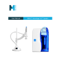
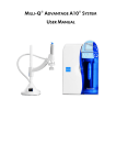
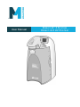
User Manual DIRECT-Q® 3 SYSTEM DIRECT-Q 3 UV SYSTEM Notice The information in this document is subject to change without notice and should not be construed as a commitment by Millipore Corporation. Millipore Corporation assumes no responsibility for any errors that might appear in this document. This manual is believed to be complete and accurate at the time of publication. In no event shall Millipore Corporation be liable for incidental or consequential damages in connection with or arising from the use of this manual. We manufacture and sell water purification systems designed to produce pure or ultrapure water with specific characteristics (μS/cm, T, TOC, CFU/ml, Eu/ml) when it leaves the water purification system provided that the Direct-Q Systems are fed with water quality within specifications, and properly maintained as required by the supplier. We do not warrant these systems for any specific applications. It is up to the end user to determine if the quality of the water produced by our systems matches his expectations, fits with norms/legal requirements and to bear responsibility resulting from the usage of the water. Copyright © 2006 MILLIPORE CORPORATION. PRINTED IN FRANCE. ALL RIGHTS RESERVED. THIS BOOK OR PARTS THEREOF MAY NOT BE REPRODUCED IN ANY FORM WITHOUT THE WRITTEN PERMISSION OF THE PUBLISHERS. FTPF09550 REV. 3 – 12/08 Trademarks Millipore and Direct-Q are registered trademarks of Millipore Corporation. Millipak, Millex and BioPak are registered trademarks of Millipore Corporation. The “M” Mark and SmartPak DQ3 are a trademark of Millipore Corporation. Tygon is a registered trademark of Norton Co. Velcro is a registered trademark of Velcro Industries, B.V. All other trademarks are trademarks of their respective manufacturers. Millipore’s Standard Warranty Millipore Corporation (“Millipore”) warrants its products will meet their applicable published specifications when used in accordance with their applicable instructions for a period of one year from shipment of the products. MILLIPORE MAKES NO OTHER WARRANTY, EXPRESSED OR IMPLIED. THERE IS NO WARRANTY OF MERCHANTABILITY OR FITNESS FOR A PARTICULAR PURPOSE. The warranty provided herein and the data, specifications and descriptions of Millipore products appearing in Millipore’s published catalogues and product literature may not be altered except by express written agreement signed by an officer of Millipore. Representations, oral or written, which are inconsistent with this warranty or such publications are not authorised and if given, should not be relied upon. In the event of a breach of the foregoing warranty, Millipore’s sole obligation shall be to repair or replace, at its option, the applicable product or part thereof, provided the customer notifies Millipore promptly of any such breach. If after exercising reasonable efforts, Millipore is unable to repair or replace the product or part, then Millipore shall refund to the customer all monies paid for such applicable product or part. MILLIPORE SHALL NOT BE LIABLE FOR CONSEQUENTIAL, INCIDENTAL, SPECIAL OR ANY OTHER INDIRECT DAMAGES RESULTING FROM ECONOMIC LOSS OR PROPERTY DAMAGE SUSTAINED BY ANY CUSTOMER FROM THE USE OF ITS PRODUCTS. Directive 2002/96 EC : For European users only The symbol “crossed bin” on a product or its packaging indicates that the product should not be treated like household waste when discarded. Instead the product should be disposed of at a location that handles discarded electric or electronic equipment. Proper disposal of equipment containing electric or electronic components will help to reduce pollution effects to the environment or to human health. Proper recycling of these products helps in environmental preservation and helps to protect natural resources. For more information about recycling of products containing electric or electronic components, please contact your local recycling representative or organisation. DECLARATION OF CONFORMITY EUROPEAN UNION EC DIRECTIVE Directive 89/336/CEE Directive 73/23/CEE Direct-Q ♦ The Direct-Q System mentioned above is manufactured in Millipore SAS - 67120 Molsheim FRANCE - facilities whose quality management system is approved by an accredited registering body to the ISO9001 Quality System Standards. ♦ We certify that these Lab Direct-Q Systems are designed and manufactured in application of the following European Council directives: - 89/336/CEE relating to Electromagnetic compatibility - 73/23/CEE relating to electrical equipment designed for use within certain voltage limits ♦ Standards to which conformity is declared as applicable are the following : - EN 61326-1: 1997: Electrical equipment for measurement, control and laboratory use – EMC requirements. - EN 61010-1: 2001: Safety requirements measurement, control, and laboratory use. for electrical equipment for Guy REYMANN Quality Assurance Manager TABLE OF CONTENTS CHAPTER 1 INTRODUCTION .......................................................... 1 1-1 USING THIS MANUAL ..................................................................................................................... 1 1-2 SAFETY INFORMATION ................................................................................................................... 1 1-3 CONTACTING MILLIPORE ............................................................................................................... 2 Internet and Email ................................................................................................................................... 2 Manufacturing Site................................................................................................................................... 2 CHAPTER 2 PRODUCT INFORMATION ........................................... 3 2-1 DIRECT-Q SYSTEM OVERVIEW ...................................................................................................... 3 2-2 DIRECT-Q PRODUCT WATER SPECIFICATIONS .............................................................................. 3 Water Flowrate Specifications................................................................................................................. 3 Product Water Quality............................................................................................................................. 3 2-3 SCHEMATIC OF MAIN COMPONENTS.............................................................................................. 4 2-4 OPERATING PRINCIPLE ................................................................................................................... 4 2-5 TECHNICAL SPECIFICATIONS ......................................................................................................... 5 Dimensions............................................................................................................................................... 5 Weight ...................................................................................................................................................... 5 Noise Level ............................................................................................................................................... 5 Electrical .................................................................................................................................................. 5 CHAPTER 3 3-1 PRE INSTALLATION .................................................... 6 INSTALLATION REQUIREMENTS ..................................................................................................... 6 Feedwater Requirements ......................................................................................................................... 6 Feedwater Connection Needed................................................................................................................ 6 Reject Flow Requirement......................................................................................................................... 6 Environmental Requirements................................................................................................................... 7 3-2 OPTIONAL EQUIPMENT YOU MAY NEED ....................................................................................... 7 Wall Mounting Bracket ............................................................................................................................ 7 External Tank Connector......................................................................................................................... 7 3-3 UNPACKING THE DIRECT-Q − WHAT’S INSIDE? ............................................................................ 8 TABLE OF CONTENTS CHAPTER 4 INSTALLATION ........................................................... 9 4-1 PREPARATION OF THE SYSTEM ...................................................................................................... 9 4-2 CONNECTION OF TUBING ............................................................................................................. 10 Feedwater Tubing .................................................................................................................................. 10 Reject Tubing ......................................................................................................................................... 11 Overflow Tubing .................................................................................................................................... 11 Tank Outlet Tubing ................................................................................................................................ 12 4-3 CONNECTION OF THE POWER CORD − TURNING ON THE SYSTEM POWER .................................. 13 Start-up Displays.................................................................................................................................... 13 4-4 INSTALLATION OF THE SMARTPAK .............................................................................................. 14 Installation ............................................................................................................................................. 14 Flush Mode............................................................................................................................................. 16 Rinsing the SmartPak............................................................................................................................. 16 4-5 INSTALLATION OF THE VENT FILTER ........................................................................................... 17 4-6 INSTALLATION OF THE TYGON TUBING ....................................................................................... 17 4-7 PURGING AIR FROM THE SYSTEM ................................................................................................ 18 4-8 HYDRATING THE SYSTEM ............................................................................................................ 18 4-9 INSTALLATION AND RINSING OF THE FINAL FILTER.................................................................... 19 4-10 HOW TO CALIBRATE THE FLOWRATE FROM THE DIRECT-Q (F02).............................................. 20 4-11 HOW TO SHOW RESISTIVITY OR CONDUCTIVITY UNITS (C01) ................................................... 22 With Temperature Compensated or non Temperature Compensated values........................................ 22 4-12 HOW TO SET THE RESISTIVITY SETPOINT (C02).......................................................................... 24 CHAPTER 5 USING THE DIRECT-Q.............................................. 26 5-1 UNDERSTANDING THE DISPLAY ................................................................................................... 26 5-2 HOW TO GET WATER FROM THE DIRECT-Q ................................................................................ 26 Product Water Using the Dispensing Button ........................................................................................ 26 RO Water Using the Tank Outlet Valve................................................................................................. 27 How to Dispense an Exact Amount of Product Water (F01) ................................................................ 28 TABLE OF CONTENTS 5-3 OPERATING MODES ...................................................................................................................... 30 Standby................................................................................................................................................... 30 Flush....................................................................................................................................................... 30 Filling Tank............................................................................................................................................ 31 Pre Operate............................................................................................................................................ 31 Dispensing.............................................................................................................................................. 32 Auto-Dispensing..................................................................................................................................... 32 5-4 HOW TO VIEW THE PRODUCT RESISTIVITY AND TEMPERATURE IN FILLING TANK MODE OR IN PRE OPERATE MODE .................................................................................................................................... 33 5-5 HOW TO VIEW THE RO PERMEATE CONDUCTIVITY IN FILLING TANK MODE OR IN PRE OPERATE MODE ........................................................................................................................................... 33 5-6 HOW TO RECIRCULATE WATER MANUALLY BEFORE DISPENSING ............................................... 34 5-7 HOW TO UNDERSTAND DIRECT-Q MESSAGES ............................................................................. 35 Pack Alarm............................................................................................................................................. 35 UV Lamp Alarm ..................................................................................................................................... 35 Flush: Open Tank Outlet Valve ............................................................................................................. 36 CHAPTER 6 MAINTENANCE ......................................................... 37 6-1 MAINTENANCE SCHEDULE ........................................................................................................... 37 6-2 HOW TO REPLACE THE SMARTPAK.............................................................................................. 38 Removing the SmartPak......................................................................................................................... 38 Installation ............................................................................................................................................. 39 Flush Mode............................................................................................................................................. 40 Rinsing the SmartPak............................................................................................................................. 40 Replacing the Vent Filter ....................................................................................................................... 41 Installing the Tygon Tubing ................................................................................................................... 41 Purging Air from the System.................................................................................................................. 41 Hydrating the System ............................................................................................................................. 41 Replacing the Final Filter...................................................................................................................... 41 6-3 HOW TO REPLACE THE FINAL FILTER .......................................................................................... 42 6-4 HOW TO CLEAN THE SCREEN FILTER........................................................................................... 43 6-5 HOW TO CALIBRATE THE TANK LEVEL (C04) ............................................................................. 44 6-6 HOW TO EMPTY THE TANK (C03) ................................................................................................ 46 TABLE OF CONTENTS 6-7 HOW TO SANITIZE THE SYSTEM ................................................................................................... 48 Things to Know BEFORE you sanitize the System and the Tank.......................................................... 48 Sanitizing the System and the Tank ....................................................................................................... 49 6-8 HOW TO SANITIZE THE TANK ONLY ............................................................................................. 53 Things to Know BEFORE you sanitize the Tank................................................................................... 53 Sanitizing the Tank................................................................................................................................. 54 6-9 HOW TO REPLACE THE UV LAMP (UV SYSTEM ONLY)............................................................... 57 Removing the UV Lamp ......................................................................................................................... 58 Installing the new UV Lamp .................................................................................................................. 59 6-10 HOW TO VIEW OR RESET THE UV LAMP TIMER (C05)................................................................ 60 How to View the Remaining Days on the UV Lamp Timer ................................................................... 60 How to Reset the UV Lamp Timer ......................................................................................................... 61 CHAPTER 7 TROUBLESHOOTING ................................................. 62 CHAPTER 8 ORDERING INFORMATION ....................................... 65 8-1 CATALOGUE NUMBERS FOR DIRECT-Q SYSTEMS ....................................................................... 65 8-2 CATALOGUE NUMBERS FOR CONSUMABLES ............................................................................... 65 8-3 CATALOGUE NUMBERS FOR ACCESSORIES.................................................................................. 65 INTRODUCTION Chapter 1 INTRODUCTION 1-1 USING THIS MANUAL This User Manual is a guide for use during the installation, normal operation and maintenance of a Direct-Q 3 or a Direct-Q 3 UV Water Purification System. ‘Direct-Q’ is used in this manual to refer to either the Direct-Q 3 or the Direct-Q 3 UV unless otherwise noted. It is highly recommended to completely read this manual and to fully comprehend its contents before attempting normal operation or maintenance of the Water Purification System. 1-2 SAFETY INFORMATION Your Direct-Q System should be operated according to the instructions in this manual. In particular, the hydraulic and electrical specifications should be followed and met. It is important to use this equipment as specified in this manual; using this equipment in a different manner may impair the safety precautions of the Direct-Q System. Symbol ! What it means This HAZARD symbol is used to refer to instructions in this manual that need to be done safely and carefully. This ATTENTION symbol is used to refer to instructions in this manual that need to be done carefully. This UV RADIATION sticker is used to refer to a position on the Direct-Q System Cabinet or inside of it where exposure to UV light is possible. This DANGER sticker is used to refer to a position on the Direct-Q System Cabinet or inside of it that could be hazardous. This ELECTRICAL GROUND sticker is used to refer to a position on the Direct-Q System Cabinet or inside where an electrical ground connection is made. This ELECTRICAL DANGER sticker is used to refer to a position on the Direct-Q System Cabinet or inside where an electrical danger could exist. -1- PRODUCT INFORMATION Chapter 2 PRODUCT INFORMATION 2-1 DIRECT-Q SYSTEM OVERVIEW DISPLAY The DISPLAY is used to monitor the water quality and system status. 2-2 DISPENSING BUTTON KEYPAD The DISPENSING BUTTON is used to get Product Water. The KEYPAD is used to access operating functions and system settings. DIRECT-Q PRODUCT WATER SPECIFICATIONS WATER FLOWRATE SPECIFICATIONS RO WATER FLOWRATE DISPENSING FLOWRATE REJECT WATER FLOWRATE (5°C < T < 35°C) 3 LPH ± 15% @ 25°C Up to 42 LPH 30 LPH PRODUCT WATER QUALITY Resistivity 18.2 MΩ.cm @ 25 °C Conductivity 0.056 μS/cm @ 25 °C < 5 μg/L (ppb) (with UV) Total Organic Carbon (TOC) < 10 μg/L (ppb) (without UV) Micro-Organisms < 1 CFU/ml (with Millipak Filter) -3- PRODUCT INFORMATION 2-3 SCHEMATIC OF MAIN COMPONENTS 8 1 2 3 6 7 5 10 4 13 12 9 14 11 2-4 1 Booster Pump 8 6 Litre Tank 2 Inlet Solenoid Valve 9 Distribution Pump 3 SmartPak DQ3 (Pretreatment and RO Cartridge) 10 UV Lamp 185 nm (UV System) 4 RO Reject Solenoid Valve 11 SmartPak DQ3 (Ion Exchange Polisher Cartridge) 5 RO Reject Capillary 12 Product Resistivity Cell 6 Check Valve 13 Point-of-Use (POU) Solenoid Valve 7 RO Permeate Conductivity Cell 14 Final Filter OPERATING PRINCIPLE Potable tap water enters the SmartPak DQ3 through the Booster Pump. The ‘SmartPak’ for the remainder of this manual) is an all-in-one twin-cartridge purification technologies. The first cartridge combines Pretreatment media and a membrane. The second cartridge contains Ion Exchange resin. The SmartPak is a needs to be periodically replaced during the maintenance of the system. SmartPak DQ3 (called containing three water Reverse Osmosis (RO) consumable device that Tap water is pretreated to protect the RO membrane from organic fouling and chlorine oxidation. The RO membrane has 2 exiting streams. The RO water is stored temporarily in the 6 Litre tank. The ions, particles, organic molecules and bacteria rejected by the RO membrane are sent to the drain via the Reject Tubing. During Dispensing mode, the Distribution Pump turns on. The RO water is pumped from the tank into the UV Lamp (UV System). The UV Lamp emits light at 185 nm and 254 nm. It is used to reduce levels of organic molecules in the water. The UV Lamp is a consumable device that needs to be periodically replaced during the maintenance of the system. The RO water is then sent to the Ion Exchange Polisher cartridge to deionize the water. The Final Filter is a membrane based filter that removes all particles and bacteria with a size greater than the filter pore size. The Final Filter is a consumable device. Product Water is regularly recirculated to enhance the quality of water delivered from the Direct-Q. -4- PRODUCT INFORMATION 2-5 TECHNICAL SPECIFICATIONS DIMENSIONS SYSTEM HEIGHT, WIDTH AND DEPTH 54 cm 14.9 cm 29.0 cm 42 cm SHIPPING BOX ♦ Height: 56 cm ♦ Width: 42 cm ♦ Depth: 64 cm WEIGHT SYSTEM Direct-Q 3 Direct-Q 3 UV Operating Weight 17.6 kg 18.2 kg Dry Weight 8.1 kg 8.6 kg Shipping Weight 13.4 kg 13.9 kg NOISE LEVEL A Direct-Q System has a maximum noise level of 50 dB at a distance of 1 metre away. ELECTRICAL ♦ 100 VAC ± 10%, 50/60 Hz. 0.68 amp source, 2 amp T (Time Lag) fuse, Power = 100 VA ♦ 120 VAC ± 10%, 50/60 Hz. 0.60 amp source, 2 amp T fuse, Power = 100 VA ♦ 230 VAC ± 10%, 50/60 Hz. 0.37 amp source, 2 amp T fuse, Power = 100 VA The source of electrical power should be within 2.5 metres of the system. The source of electrical power must be earth grounded. -5- PRE INSTALLATION Chapter 3 PRE INSTALLATION 3-1 INSTALLATION REQUIREMENTS FEEDWATER REQUIREMENTS Type of Feedwater Potable Flowrate ≥ 40 LPH Minimum Pressure ≥ 0.5 bar Maximum Pressure ≤ 6 bar Conductivity < 2000 μS/cm Temperature 5 to 35 °C pH 4 - 10 Fouling Index < 10 Iron < 0.1 ppm as CaCO3 Aluminum < 0.05 ppm as CaCO3 Manganese < 0.05 ppm as CaCO3 Free Chlorine < 1 ppm Langelier Saturation Index < +0.2 TOC < 2000 ppb FEEDWATER CONNECTION NEEDED Feedwater Piping Connection 1/2 inch Male GAZ, NPTM or BSPM REJECT FLOW REQUIREMENT Drain Capacity 30 LPH -6- PRE INSTALLATION ENVIRONMENTAL REQUIREMENTS Indoor Use Only 3-2 Storage Temperature 5 °C < T < 40 °C Operating Temperature 5 °C < T < 40 °C Relative Humidity Should not exceed 80% for temperatures below 31 °C Should stay within 50% to 80% between 31 °C and 40 °C. Altitude < 3000 metres Installation Category II Pollution Degree 2 OPTIONAL EQUIPMENT YOU MAY NEED WALL MOUNTING BRACKET The Millipore Catalogue Number for the Wall Mounting Bracket is WMBSMT001. The mounting hardware for attaching the bracket to a wall is not included and must be supplied. EXTERNAL TANK CONNECTOR The Millipore Catalogue Number for a Tank Connector Kit is TANKPECKT. An external tank holding up to 30 Litres can be used instead of the internal 6 Litre tank. The Tank Connector Kit is used to connect the 30 L tank to the system. The mounting hardware for connecting the external tank to the system is not included and must be supplied. The Millipore Catalogue Number for the 30 L PE Reservoir is TANKPE030. -7- PRE INSTALLATION 3-3 UNPACKING THE DIRECT-Q − WHAT’S INSIDE? Open the Direct-Q System Shipping Box. Use the checklist included in the Accessories Bag to make sure all items were shipped and are accounted for. It is highly suggested to become familiar with the items that are shipped since these will be used in the Installation section of this manual. Contact Millipore if an item is missing. -8- INSTALLATION Chapter 4 INSTALLATION 4-1 PREPARATION OF THE SYSTEM Open the front cover. Locate the tie wrap used to hold the Booster Pump in place during shipping (A). Press on the tab of the tie wrap (B). Remove and pull the tie wrap out. Locate the protective foam found at the UV lamp cable. Remove it (C). A B C -9- INSTALLATION 4-2 CONNECTION OF TUBING Rotate the Direct-Q so you can see the back of the system (see photo A). A 3 1. FEEDWATER TUBING 1 3. OVERFLOW TUBING 2 2. REJECT TUBING 4 4. TANK OUTLET FEEDWATER TUBING Locate the Feedwater Tubing exiting from the bottom middle of the system (B). A 1/2 inch Female GAZ fitting with a screen filter is attached at the end of this tubing. Unroll it until the fitting reaches the Feedwater source. Apply white tape on the thread of the 1/2 inch Male GAZ valve or fitting of the Feedwater source. Connect the fitting to the valve (C). B C FEEDWATER TUBING - 10 - INSTALLATION REJECT TUBING Locate the Reject Tubing exiting from the bottom middle of the system (D). Unroll it. Secure the tubing into a sink or drain. D REJECT TUBING OVERFLOW TUBING Locate the Overflow Tubing exiting from the bottom right of the system (E). Unroll it. Secure the tubing into a sink or drain. E OVERFLOW TUBING - 11 - INSTALLATION TANK OUTLET TUBING Locate the Tank Outlet Valve, the Tank Outlet Tubing and the adaptor fitting in the Accessories Bag. Install the Tank Outlet Valve and Tubing as shown (F, G, and H). Open the Tank Outlet Valve (I). This allows the tank to be emptied of any water in it. This is necessary when the SmartPak is flushed with water after it is installed. F G H I - 12 - INSTALLATION 4-3 CONNECTION OF THE POWER CORD − TURNING ON THE SYSTEM POWER Open the front cover of the system (A). This will allow the system to go into STANDBY mode once the system is powered. Plug the Power Cord into the system (B). Plug the other end of the Power Cord into an appropriate source of electrical power (i.e. wall outlet). The system is immediately powered. Open the Feedwater Supply Valve. A START-UP DISPLAYS Once the system is powered, the system will start to display information about the software before going into STANDBY mode (C). B C - 13 - INSTALLATION 4-4 INSTALLATION OF THE SMARTPAK ATTENTION ! HAZARD Open the Tank Outlet Valve before installing a new SmartPak. This keeps the tank from filling until the SmartPak is rinsed out (A). Do not touch the UV Lamp when replacing the SmartPak. INSTALLATION Make sure the front cover is opened. STANDBY should be viewed on the Display (B). Remove the SmartPak from its shipping box. Remove the protective caps on the ports of the SmartPak and from the system. Locate the O-rings on the ports (C). Wet them with water. It is preferable to wet them with ultrapure water. A B C - 14 - INSTALLATION Install the SmartPak until it is fully seated into the system ports as shown (D, E and F). Close the front cover. D NOTE: The Tank Outlet Valve should be left open (G). G E F - 15 - INSTALLATION FLUSH MODE The Tank Outlet Valve should be left open during FLUSH mode. ATTENTION The system will now go into FLUSH mode for 15 minutes (H). This is done to empty the SmartPak of air and hydrate the material inside. When FLUSH mode is finished, the system will go into FILLING TANK mode automatically (I). H RINSING THE SMARTPAK Let FILLING TANK mode run for 15 minutes with the Tank Outlet Valve open. This will completely rinse the purification media inside the SmartPak. Close the Tank Outlet Valve (J). The tank will start to fill up with water. It could take approximately 1.5 to 2 hours to fill the tank. When it is full, the Display will indicate a full tank by illuminating the symbols representing the Tank Level (see Section 5-1 Understanding the Display). I The Vent Filter needs to be installed. See Section 4-5 Installation of the Vent Filter. NOTE: for sensitive applications, it is recommended to leave the system in FILLING TANK overnight to ensure complete rinsing of the RO membrane. J - 16 - INSTALLATION 4-5 INSTALLATION OF THE VENT FILTER Obtain the Vent Filter. Insert the Vent Filter firmly into the port (A, B). A 4-6 B INSTALLATION OF THE TYGON TUBING Locate the clear Tygon Tubing and the Barbed Fitting from the Accessories Bag. Screw the Barbed Fitting onto the bottom end of the POU Dispenser (C). ATTENTION Do not use any white tape on the threads of the Barbed Fitting. An O-ring is located inside the POU Dispenser to ensure water tightness between the threads of the POU Dispenser and the Barbed Fitting. Push one end of the Tygon Tubing onto the end of the Barbed Fitting (D). Place the other end of the Tygon Tubing in a sink. C D - 17 - INSTALLATION 4-7 PURGING AIR FROM THE SYSTEM At this time you should have installed the SmartPak, Barbed Fitting and the Tygon Tubing. Air trapped in the SmartPak should now be purged from the system. Verify that you have a full tank of RO water by viewing the Tank Level display (A). Press the Dispensing Button once to put the system into DISPENSING mode (B). Dispense the full tank of water from the system. The system will go into FILLING TANK mode when the tank level is below the 60% level (C). When the tank level reaches the minimum level, the system will finish dispensing water. 4-8 A B HYDRATING THE SYSTEM At this time, the Final Filter is not installed. Leave the system overnight or for several hours in FILLING TANK mode or PRE OPERATE mode (see Section 5-3 Operating Modes). The system will regularly recirculate water and rinse off purification media inside the SmartPak. Do not leave the system in STANDBY mode. (The next morning) Press the Dispensing Button once to put the system into DISPENSING mode. Allow about 1 Litre of water to be dispensed from the system. Press the Dispensing Button once again. The system will finish dispensing water. Remove the Tygon Tubing and the Barbed Fitting from the POU Dispenser. The Final Filter needs to be installed. See Section 4-9 Installation and Rinsing of the Final Filter. - 18 - C INSTALLATION 4-9 INSTALLATION AND RINSING OF THE FINAL FILTER Obtain a Final Filter. It can be the Millipak Express 20 or the BioPak Ultrafiltration Cartridge. Remove the Tygon Tubing and the Barbed Fitting from the POU Dispenser. Screw the Final Filter onto the end of the POU Dispenser. The Final Filter should be turned until it is hand tight (A). Do not over tighten the Final Filter. ATTENTION Do not use white tape on the threads of the Final Filter. The POU Dispenser has an O-ring inside which provides a watertight seal. Press the Dispensing Button once. This will bring the system into DISPENSING mode. (If your Final Filter is a Millipak) Locate the air vent valve on the top side of the Millipak. Open this slowly but do not remove it from the Millipak (B). Allow any air on the clear side of the Millipak to be vented out. ATTENTION Air will not pass through the membrane filter in the Millipak. If there is trapped air in the Millipak, then a reduction in Product Water flowrate can result. Dispense about 1 Litre of water. Make sure all air is purged out. Press the Dispensing Button once again. The system will finish dispensing water. Leave the system in FILLING TANK mode. ATTENTION It is highly recommended not to put Tygon Tubing or any other type of tubing on the end of the Final Filter. This can compromise the Product Water quality (bacteria can grow in the Tygon Tubing). The Water System is now ready for use. A B - 19 - INSTALLATION 4-10 HOW TO CALIBRATE THE FLOWRATE FROM THE DIRECT-Q (F02) Before calibrating the Product flowrate from the Direct-Q, you will need a 1 Litre graduated cylinder to measure the total volume of water that will be dispensed. The Final Filter should be installed. 1. Press the Main and “-“ Buttons together to enter the menu. The Display will show F01. 2. Press the Main Button once. The Display will show F02 and the 60 second timer. The graduated cylinder will be blinking. 3. Press the Dispensing Button once. The system will dispense water for 60 seconds. The Display will show the timer counting down. NOTE: If you press the Dispensing Button again or if the Tank Level display is at the 10% level before 60 seconds have elapsed, then the system will stop dispensing water. Calibration of the flowrate is cancelled. CONTINUED ON NEXT PAGE - 20 - INSTALLATION 4. Measure the total volume of water (in Litres) dispensed from the system using a1L graduated cylinder. 5. Press the “+” or “-“ Button to match the volume Display to the volume measured. 6. To exit the menu, press and hold the Main Button for 2 seconds. To display the next menu option, press the Main Button once. The Product Water flowrate is now calibrated. - 21 - INSTALLATION 4-11 HOW TO SHOW RESISTIVITY OR CONDUCTIVITY UNITS (C01) WITH TEMPERATURE COMPENSATED OR NON TEMPERATURE COMPENSATED VALUES Temperature compensation is a way of ‘standardizing’ Resistivity or Conductivity to measurements that would be seen if the water temperature was 25 °C. 1. Press the Main and “+“ Buttons together to enter the menu. The Display will show C01 and the units chosen. The following Display shows Temperature Compensated Resistivity Units: MΩ.cm @25 °C. 2. Press the “+” or “-“ Button to select Non Temperatu re Compensated Resistivity Units: MΩ.cm. 3. Press the “+” or “-“ Button to select Temperature Compensated Conductivity Units: μS/ cm @25 °C. - 22 - INSTALLATION 4. Press the “+” or “-“ Button to select Non Temperature Compensated Conductivity Units: μS/cm. 5. To exit the menu, press and hold the Main Button for 2 seconds. To display the next menu option, press the Main Button once. - 23 - INSTALLATION 4-12 HOW TO SET THE RESISTIVITY SETPOINT (C02) The Resistivity Setpoint is used to inform you when the Product resistivity is low. When the resistivity is below the setpoint, the Resistivity display will flash and the red Pack Alarm will be blinking (see Section 5-7 How to Understand Direct-Q Messages). The factory default resistivity value is set to15 MΩ. cm @25 °C. 1. Press the Main and “+“ Buttons together to enter the menu. The Display will show C01. 2. Press the Main Button once. The Display will show C02 and the Resistivity Setpoint value. 3. Press the “+” or “-“ Button to adjust the Resistivity Setpoint from 1.0 MΩ.cm @25 °C to18.0 MΩ.cm @25 °C. If Conductivity Units are chosen in C01, then the Setpoint can be adjusted from 0.999 μS/cm @25 °C to 0.055 μS/cm @25 °C. NOTE: The Conductivity Setpoint display needs to be multiplied by 0.001 to get the real value. For example, if the Display reads “055” μS/cm @25 °C, then you would multiply 055 x 0.001 = 0.055. Thus, the real Conductivity Setpoint reading is 0.055 μS/cm @25 °C. - 24 - INSTALLATION 4. To exit the menu, press and hold the Main Button for 2 seconds. To display the next menu option, press the Main Button once. - 25 - USING THE DIRECT-Q Chapter 5 USING THE DIRECT-Q 5-1 UNDERSTANDING THE DISPLAY The Display is used to view information about the Operating Modes, the Operating Parameters, Maintenance or Alarm messages and the Tank Level. Operating Modes 100 % TANK FULL Operating Parameters Tank Level Maintenance or Alarms 10 % UV System only 5-2 HOW TO GET WATER FROM THE DIRECT-Q PRODUCT WATER USING THE DISPENSING BUTTON There are two ways to get water using the Dispensing Button: Press once and release. To stop dispensing water, Dispensing Button once again. OR press the Press and hold down. To stop dispensing water, release the Dispensing Button. The system will dispense water continuously until the 10% Tank Level display is reached. At the 10% level, the system will automatically stop dispensing water. - 26 - USING THE DIRECT-Q RO WATER USING THE TANK OUTLET VALVE RO Water is obtained from the Tank Outlet. Open the Tank Outlet Valve when RO Water is needed. TANK OUTLET VALVE - 27 - USING THE DIRECT-Q HOW TO DISPENSE AN EXACT AMOUNT OF PRODUCT WATER (F01) 1. Press the Main and “-“ Buttons together to enter the menu. The Display will show F01. 2. Press the “+” or “-“ Button to adjust the exact amount of Product Water (in Litres) needed. Pre-set volumes of water can be adjusted from 0.25 L to 9.75 L in 0.25 increments. NOTE: The accuracy of this is dependent upon the accuracy of the Flow Calibration performed in Section 4-10. 3. Press the Dispensing Button once. The system will dispense water. The Display will show the amount of water dispensed and the Product resistivity. NOTE: To stop dispensing water, press the Dispensing Button once again. - 28 - USING THE DIRECT-Q 4. To exit the menu, press and hold the Main Button for 2 seconds. To display the next menu option, press the Main Button once. - 29 - USING THE DIRECT-Q 5-3 OPERATING MODES STANDBY STANDBY mode is displayed when the front cover is removed. The system will depressurize during which STANDBY will be blinking on the Display for 10 seconds. All system operations are disabled. STANDBY mode is selected before attempting maintenance on the system. FLUSH FLU (FLUSH) mode is displayed for 15 minutes after a new SmartPak has been installed and the front cover has been closed. FLUSH mode allows tap water to enter and rinse the new SmartPak. The Tank Outlet Valve must be opened during the FLUSH cycle to keep the tank from filling until the SmartPak is rinsed. FLUSH mode is stopped if the front cover is removed to go into STANDBY mode. When the front cover is closed, FLUSH mode resumes from the last remaining time on the Display. If the system is powered OFF during FLUSH mode and powered back ON, then a new FLUSH cycle will start. The system will have a 2 minute FAST FLUSH cycle every 24 hours of PRE OPERATE mode. - 30 - USING THE DIRECT-Q FILLING TANK FILLING TANK mode is displayed when the tank is being filled with RO water until the 100% Tank Level display. FILLING TANK mode is launched automatically when the Tank Level display is below the 60% level or after a FLUSH cycle has been completed. FILLING TANK mode Water can be dispensed or can be periodically recirculated during FILLING TANK mode if the Tank Level display is above the 10% level. Dispensing or Recirculation during FILLING TANK mode PRE OPERATE PRE OPERATE mode is displayed when the system is not dispensing water and not in FILLING TANK mode. The Tank Level display is between the 60% level and TANK FULL level. The system will have a 3-minute auto-recirculation every 2 hours in PRE OPERATE mode. The Distribution Pump turns on. This will enhance the quality of the Product Water delivered from the system. Recirculation can also be activated manually for up to 3 minutes. The resistivity and temperature of the Product Water is displayed during recirculation. The resistivity and temperature remain displayed for up to 10 seconds after recirculation is finished. - 31 - USING THE DIRECT-Q DISPENSING DISPENSING mode is displayed when Product Water is being dispensed. DISPENSING mode occurs because the Dispensing Button was pressed down. The Distribution Pump turns on. The resistivity and temperature of the Product Water is displayed during dispensing. The resistivity and temperature remain displayed for up to 10 seconds after dispensing is stopped. AUTO-DISPENSING AUTO-DISPENSING mode is displayed when selecting menu option F01. AUTO-DISPENSING mode is used to dispense pre-set volumes of water from the Direct-Q. The Distribution Pump turns on. The amount of water dispensed and the resistivity are shown while water is being dispensed. The resistivity remains displayed for up to 10 seconds after dispensing is stopped. - 32 - USING THE DIRECT-Q 5-4 HOW TO VIEW THE PRODUCT RESISTIVITY AND TEMPERATURE IN FILLING TANK MODE OR IN PRE OPERATE MODE Press: The Display will show the last Product resistivity and temperature values measured during DISPENSING mode or during RECIRCULATION. The values are displayed for 5 seconds. NOTE: The Product resistivity and temperature are displayed automatically during DISPENSING mode or during RECIRCULATION. 5-5 HOW TO VIEW THE RO PERMEATE CONDUCTIVITY IN FILLING TANK MODE OR IN PRE OPERATE MODE Press: The Display will show the RO Permeate Water conductivity value that was measured during Filling Tank mode. The displayed value is not a real-time value. It is the last permeate conductivity value memorized after the system was in Dispensing Mode. The value is displayed for 5 seconds. NOTE: The units are displayed in μS/cm only. - 33 - USING THE DIRECT-Q 5-6 HOW TO RECIRCULATE WATER MANUALLY BEFORE DISPENSING This option is used to enhance the quality of the Product Water before dispensing water. The Distribution Pump will turn on and water will recirculate for up to 3 minutes. An auto-recirculation occurs for 3 minutes every 2 hours. Press: The Display will show the Product resistivity and temperature. NOTE: To dispense water, press the Dispensing Button during recirculation. Recirculation will stop and water will be dispensed. - 34 - USING THE DIRECT-Q 5-7 HOW TO UNDERSTAND DIRECT-Q MESSAGES PACK ALARM The system will prompt you to change the SmartPak using a red Pack Alarm icon. The Display will show the red Pack Alarm blinking. The SmartPak is changed due to either the amount of time it has been used or from the amount of water that has passed through it. When the Resistivity display is blinking, the red Pack Alarm will also be blinking. This indicates that the SmartPak should be replaced. This message is shown when the Product resistivity is less than the Resistivity Setpoint. The Resistivity Setpoint can be seen in menu option C02 When the red Pack Alarm is displayed as a steady icon, the SmartPak is not installed correctly or not installed at all. If the SmartPak has been reinstalled and the Alarm is still displayed, then contact Millipore. UV LAMP ALARM The system will prompt you to change the UV Lamp using a red UV Lamp Alarm icon. The Display will show the red UV Lamp Alarm blinking. The message is shown when the UV Timer displays 0 days. The UV Timer can be viewed in menu option C05. The replacement of the UV Lamp involves the installation of a new UV Lamp and a manual reset of the UV Timer. When the red UV Lamp Alarm is displayed as a steady icon, the UV Lamp is not installed correctly or not installed at all. If the UV Lamp has been reinstalled and the Alarm is still displayed, then contact Millipore. - 35 - USING THE DIRECT-Q FLUSH: OPEN TANK OUTLET VALVE Before FLUSH mode starts, the tank has to be emptied of water. The FLU counter display will be blinking if the system has detected that there is water in the tank. The Tank Outlet Valve must be opened. The system will automatically resume FLUSH mode when the tank is emptied of water. - 36 - MAINTENANCE Chapter 6 MAINTENANCE 6-1 MAINTENANCE SCHEDULE WHAT TO DO WHEN? HOW TO? When the Pack Alarm display is blinking. SmartPak Replacement See Section 6-2. When the system resistivity display is blinking. After a system or tank sanitization. Final Filter Replacement The Final Filter is replaced when the SmartPak is replaced or when the Product Water flowrate drops. See Section 6-3. Vent Filter Replacement Replaced when the SmartPak is replaced. See Section 4-5. When the Final Filter is replaced, or periodically. See Section 4-10. Periodically. See Section 6-5. Flow Calibration Tank Level Calibration UV Lamp Replacement and UV Timer Reset Screen Filter Cleaning When the UV Lamp Alarm display is blinking. See Sections 6-9 and 6-10. 2 times a year or as necessary. Sanitization of the System Once a year. The SmartPak will have to be replaced after the sanitization of the system. Sanitization of the Tank Once a year. - 37 - See Section 6-4. See Sections 6-7 and 6-6. See Section 6-8. MAINTENANCE 6-2 HOW TO REPLACE THE SMARTPAK ATTENTION ! HAZARD Open the Tank Outlet Valve before installing a new SmartPak. This keeps the tank from filling until the SmartPak is rinsed out (A). Do not touch the UV Lamp when replacing the SmartPak. A REMOVING THE SMARTPAK Open the front cover to go into STANDBY mode. Wait for the system to depressurize. The Display will show STANDBY blinking for 10 seconds. Remove the Final Filter. Press your thumbs on the system (A). Swing the pack towards you (B). Remove the pack from the system (C). B C - 38 - MAINTENANCE INSTALLATION Remove the new SmartPak from its shipping box. Remove the protective caps on the ports of the SmartPak. Locate the O-rings on the ports. Wet them with water. It is preferable to wet them with ultrapure water. Install the SmartPak until it is fully seated into the system ports as shown (D, E and F). CLOSE THE FRONT COVER. NOTE: The Tank Outlet Valve should be left open (G). D E G F - 39 - MAINTENANCE FLUSH MODE The Tank Outlet Valve should be left open during FLUSH mode. ATTENTION H The system will now go into FLUSH mode for 15 minutes (H). This is done to empty the SmartPak of air and hydrate the material inside. When FLUSH mode is finished, the system will go into FILLING TANK mode automatically (I). RINSING THE SMARTPAK Let FILLING TANK mode run for 15 minutes with the Tank Outlet Valve open. This will rinse the purification media inside the SmartPak. Close the Tank Outlet Valve (J). The tank will start to fill up with water. It could take approximately 1. 5 to 2 hours to fill the tank. When it is full, the Display will show the Tank Level filled to the 100% level. I NOTE: for sensitive applications, it is recommended to leave the system in FILLING TANK overnight to ensure complete rinsing of the RO membrane. J - 40 - MAINTENANCE REPLACING THE VENT FILTER The Vent Filter should be replaced whenever the SmartPak is replaced. Remove the Vent Filter (L). Insert the new Vent Filter into the fitting. See Section 4-5 Installation of the Vent Filter. L INSTALLING THE TYGON TUBING Install the Barbed Fitting and Tygon Tubing (M). See Section 4-6 Installation of the Tygon Tubing. M PURGING AIR FROM THE SYSTEM See Section 4-7 Purging Air from the System. HYDRATING THE SYSTEM Hydrate the system (N). See Section 4-8 Hydrating the System. REPLACING THE FINAL FILTER See Section 6-3 How to Replace the Final Filter (O). The System is now ready for use. N O - 41 - MAINTENANCE 6-3 HOW TO REPLACE THE FINAL FILTER The Final Filter is normally replaced when the SmartPak is replaced or at an earlier time if it becomes clogged. A clogged Final Filter can reduce the Product Water flowrate. ATTENTION Make sure the SmartPak has been hydrated overnight. Remove the used Final Filter. Screw the new Final Filter onto the end of the POU Dispenser. The Final Filter should be turned until it is hand tight (A). Do not over tighten the Final Filter. ATTENTION Do not use white tape on the threads of the Final Filter. The POU Dispenser has an O -ring inside which provides a watertight seal. (If your Final Filter is a Millipak) Locate the air vent valve on the top side of the Millipak. Open this slowly but do not remove it from the Millipak (B). Allow any air on the clear side of the Millipak to be vented out. ATTENTION Air will not pass through the membrane filter in the Millipak. If there is trapped air in the Millipak, then a reduction in Product Water flowrate can result. Dispense about 1 Litre of water. Make sure all air is purged out. Press the Dispensing Button once again. The system will finish dispensing water. Leave the system in FILLING TANK mode. The Water System is now ready for use. A B At this time, it is highly recommended to recalibrate the Product Water flowrate. See Section 4-10 How to Calibrate the Flowrate from the Direct-Q. - 42 - MAINTENANCE 6-4 HOW TO CLEAN THE SCREEN FILTER The purpose of the Screen Filter is to prevent large particles or other debris from entering the system. If the Screen Filter becomes blocked with debris, then the Feedwater will not flow freely to the system. It is recommended to clean the Screen Filter twice a year or whenever it may have become clogged. Close the Feedwater Supply Valve. Open the front cover to let the system go into STANDBY mode. Locate the Screen Filter. This will be located where the Feedwater 8 mm OD Tubing originates. Unscrew the collar that holds the Feedwater Tubing to the barbed end of the fittings (A). Pull the tubing off of the fitting. Unscrew the Screen Filter from the Feedwater pipe. Go to a sink and flush tap water backwards through the Screen Filter. The water should flow through the barbed end first. Any trapped debris on the Screen Filter will be flushed out (B). Apply 3-4 turns of new white tape to the threads of the Feedwater Pipe in a clockwise direction. Screw the Screen Filter back onto the Feedwater Supply Pipe. Attach the Feedwater Tubing back onto the Barbed Fitting (C). Open the Feedwater Supply Valve. Close the front cover. Leave the system in PRE OPERATE mode. A B C - 43 - MAINTENANCE 6-5 HOW TO CALIBRATE THE TANK LEVEL (C04) Before calibrating the tank level, the tank needs to be filled to the 100% level or TANK FULL. 1. Press the Main and “+“ Buttons together to enter the menu. The Display will show C01. 2. Press the Main Button 3 times. The Display will show C04. The highest Tank Level display will be blinking. This means that the highest water level is ready to be calibrated. 3. Press the “+” and “-“ Buttons together to enter the highest water level. The Display will show the lowest Tank Level (red level) display blinking. NOTE: The highest and lowest tank level must be calibrated together or else the tank level is not calibrated. CONTINUED ON THE NEXT PAGE - 44 - MAINTENANCE 4. Open the Tank Outlet Valve. Allow the tank to be emptied to its lowest water level. NOTE: The lowest water level is not calibrated if the amount of water emptied from the tank is less than 10%. 5. Close the Tank Outlet Valve. 6. Press the “+” and “-“ Buttons together to enter the lowest water level. The Display will exit the menu option and go into FILLING TANK mode. The Tank Level is now calibrated. NOTE: If the Display remains in the menu option and the highest tank level is blinking, then the tank level was not calibrated. The amount of water emptied from the tank was not enough (less than 10%). The tank needs to be emptied to its lowest water level. Allow the tank to fill to the 100% level and perform the calibration again. - 45 - MAINTENANCE 6-6 HOW TO EMPTY THE TANK (C03) The tank can be fully emptied of water through the POU Dispenser. This option is used when performing a system sanitization. Before emptying the tank, it is recommended to remove the Final Filter and to install the Barbed Fitting and Tygon Tubing. Place the other end of the Tygon Tubing in a sink. 1. Press the Main and “+“ Buttons together to enter the menu. The Display will show C01. 2. Press the Main Button 2 times. The Display will show C03. 3. Press the “+” and “-“ Buttons together. The system will dispense all the water in the tank through the POU Dispenser. The Tank Level display will be blinking. NOTE: To stop emptying the tank, press the Dispensing Button. - 46 - MAINTENANCE 4. When the system has finished emptying the tank, the system will start FILLINK TANK mode automatically. - 47 - MAINTENANCE 6-7 HOW TO SANITIZE THE SYSTEM A system sanitization is performed to eliminate bacteria growth in both the system and in the tank. It is recommended to sanitize the system at least once a year. THINGS TO KNOW BEFORE YOU SANITIZE THE SYSTEM AND THE TANK ! HAZARD All safety precautions must be followed when handling Hydrogen Peroxide. Rubber gloves, safety goggles and a lab coat must be worn to avoid any skin and body contact. During a system sanitization, the tank will also be sanitized. You will need a minimum Tank Level display of at least 50% (A). Locate the clear elbow fitting, the clear tubing and the syringe in the Sanitization Kit (B). You will need 200 ml of 30% Hydrogen Peroxide solution and 200 ml of purified water. Millipore does not sell Hydrogen Peroxide but it is readily available through most Scientific Supply Companies. It is recommended to sanitize the system near the time the SmartPak would normally be replaced. The SmartPak, the Final Filter and the Vent Filter will need to be replaced after the sanitization is completed. The system will not be able to deliver Product Water while the system is being sanitized. ATTENTION A The total time needed to sanitize the system is at least 4.5 hours. B - 48 - MAINTENANCE SANITIZING THE SYSTEM AND THE TANK Open the front cover to let the system go into STANDBY mode (C). Remove the Vent Filter and install the clear elbow fitting from the Sanitization Kit (D). Introduce the male connector of the clear tubing firmly into the elbow fitting (E). Inject 200 ml (1 ml = 1 cc) of Hydrogen Peroxide solution (30%) into the 6 Litre tank via the clear tubing (F). Rinse the air vent port with 200 ml of purified water. Close the front cover (G). The system will now go into FILLING TANK mode. Let the tank fill up to the 100% level (H). C D E F - 49 - MAINTENANCE G H - 50 - MAINTENANCE Let the system stand for 1 hour for effective bacteria elimination. (After 1 hour) Remove the Final Filter. Install the Barbed Fitting and Tygon Tubing (I). Perform an EMPTY TANK (C03) to dispense all the water in the tank (J). Once the tank is empty, the system will now go into FILLING TANK mode. Let the tank fill up to the 100% level (K). Perform an EMPTY TANK (C03) again to dispense all the water in the tank (L). Open the front cover to let the system go into STANDBY mode (M). The SmartPak, the Vent Filter and the Final Filter will now have to be replaced. Refer to the earlier Maintenance sections for replacement instructions. I J K L - 51 - MAINTENANCE M - 52 - MAINTENANCE 6-8 HOW TO SANITIZE THE TANK ONLY A tank sanitization is performed to eliminate bacteria growth in the tank only. It is recommended to sanitize the tank at least once a year. THINGS TO KNOW BEFORE YOU SANITIZE THE TANK ! HAZARD All safety precautions must be followed when handling Hydrogen Peroxide. Rubber gloves, safety goggles and a lab coat must be worn to avoid any skin and body contact. If you have performed a system sanitization, then you do not need to perform a tank sanitization. You will need a minimum Tank Level display of at least 50% (A). Locate the clear elbow fitting, the clear tubing and the syringe in the Sanitization Kit (B). You will need 200 ml of 30% Hydrogen Peroxide solution and 200 ml of purified water. Millipore does not sell Hydrogen Peroxide but it is readily available through most Scientific Supply Companies. The Vent Filter will need to be replaced after the sanitization is completed. The system will not be able to deliver Product Water while the system is being sanitized. ATTENTION A The total time needed to sanitize the tank is at least 4.5 hours. B - 53 - MAINTENANCE SANITIZING THE TANK Open the front cover to go into STANDBY mode (C). Remove the Vent Filter and install the clear elbow fitting from the Sanitization Kit (D). Introduce the male connector of the clear tubing firmly into the elbow fitting (E). Inject 200 ml (1 ml = 1 cc) of Hydrogen Peroxide solution (30%) into the 6 Litre tank via the clear tubing (F). Rinse the air vent port with 200 ml of purified water. Close the front cover (G). The system will now go into FILLING TANK mode. Let the Tank Level display go up to the 100% level (H). C D E F - 54 - MAINTENANCE G H - 55 - MAINTENANCE When the tank is full, open the front cover to go into STANDBY mode (I). Let the system stand for 1 hour for effective bacteria elimination. (After 1 hour) Check that the Tank Outlet Tubing is secured into the drain. Open the Tank Outlet Valve to drain all the water from the tank (J). Close the Tank Outlet Valve (K). Close the front cover (L). The system will now go into FILLING TANK mode. Let the tank level fill up to the 100% level. I J K L Repeat steps I, J, K and L: Open the front cover to go into STANDBY mode (I). Check that the Tank Outlet Tubing is secured into the drain. Open the Tank Outlet Valve to drain all the water from the tank (J). Close the Tank Outlet Valve (K). Close the front cover (L). The system will now go into FILLING TANK mode. The tank is now sanitized. - 56 - MAINTENANCE 6-9 HOW TO REPLACE THE UV LAMP (UV SYSTEM ONLY) The red UV Lamp Alarm will be blinking on the Display when it is time to exchange the UV Lamp. The message is shown when the UV Timer has reached 0 days (see Section 6-10 How to Reset the UV Lamp Timer). Open the front cover to go into STANDBY mode (A). Unplug the electrical cord to power OFF the system (B). ! HAZARD Remove the Final Filter. Remove the SmartPak (C). No electrical power should be going to the system at this time. Accidental exposure to ultraviolet light can cause damage to the eyes and skin. A B C - 57 - MAINTENANCE REMOVING THE UV LAMP Detach the Velcro® belt of the UV housing. Pull the UV housing out so that the UV Lamp cable is accessible (D). NOTE: Use the gloves supplied with the UV replacement kit. Pull the UV Lamp out of the UV housing by its electrical cable (E). Unplug the electrical cable from the UV Lamp (F). ATTENTION The UV Lamp contains metallic Mercury. Please dispose of the used UV Lamp in a manner that is environmentally safe. D E F - 58 - MAINTENANCE INSTALLING THE NEW UV LAMP Ensure that you use the gloves supplied with the UV replacement kit. Plug the electrical cable to the new UV Lamp (G). Carefully insert the UV Lamp into the UV housing (H). Attach the UV housing with the Velcro belt (I). Install the SmartPak (J). Install the Final Filter. G H ATTENTION If the SmartPak is not being replaced, then reinstall the old SmartPak BEFORE powering ON the system. Otherwise, the system will go into FLUSH mode for 15 minutes during which no Product Water will be available. Close the front cover. Plug the electrical cord to power ON the system. Reset the UV Timer. See Section 6-10 How to View or Reset the UV Lamp Timer (C05). I J - 59 - MAINTENANCE 6-10 HOW TO VIEW OR RESET THE UV LAMP TIMER (C05) The UV Lamp Timer should be reset only after the UV Lamp has been replaced (see Section 6-9 How to Replace the UV Lamp). The UV Lamp Timer displays the time left until the UV Lamp needs to be replaced. The Display will show the red UV Lamp Alarm icon blinking when the Timer reaches 0 days. This message is displayed until the UV Lamp is replaced and the UV Lamp Timer is reset. HOW TO VIEW THE REMAINING DAYS ON THE UV LAMP TIMER 1. Press the Main and “+“ Buttons together to enter the menu. The Display will show C01. 2. Press the Main Button 4 times. The Display will show C05 and the days left on the UV Timer. 3. To exit menu, press and hold the Main Button for 2 seconds. To display the next menu option, press the Main Button once. - 60 - MAINTENANCE HOW TO RESET THE UV LAMP TIMER 4. Press the Main and “+“ Buttons together to enter the menu. The Display will show C01. 5. Press the Main Button 4 times. The Display will show C05 and “0” days left on the UV Timer. 6. Press the “+” and “-“ Buttons together. This will reset the UV Timer to 500 (days). The Display will exit the menu. The UV Timer has been reset. - 61 - TROUBLESHOOTING Chapter 7 TROUBLESHOOTING PROBLEM The Display screen is blank. POSSIBLE CAUSES The power cord is not plugged in. ¾ Check that the power cord is plugged in. No source power. ¾ Check the source electrical power. Main Power Fuse is blown. ¾ Contact Millipore. The Tank Outlet Valve is open. The water in the tank is diverted into the drain. No water is kept in the tank. ¾ Close the Valve. ¾ Check source. ¾ See Section 6-5 How to Calibrate the Tank Level (C04). ¾ Replace the SmartPak. ¾ Allow the system to go into FILLING TANK mode until there is enough water available in the tank, viewed by the Tank Level display. ¾ Close the Valve. ¾ Vent all air Millipak Filter. ¾ Replace the Final Filter, see Section 6-3 How to Replace the Final Filter. In FILLING TANK mode, the Tank Level display is not rising. (The Tank Level display should be rising steadily.) Low water flow or no water flow when the Dispensing Button is pressed. DISPENSING mode continuously runs even when the Tank Level display is below 10%. AUTO-DISPENSING mode is not accurate. WHAT TO DO of electrical The tank level is calibrated properly. The RO membrane is dirty or clogged. not The water level is less than 10%. No dispensing is allowed. The Tank Outlet Valve is open. The tank is not filling up with water. Millipak Filter is air locked. Final Filter is clogged. Tank the of Outlet Feedwater Tank Outlet from the The water level is not calibrated. The system does not detect the minimum level to disable DISPENSING mode. ¾ Calibrate the tank level. See Section 6-5 How to Calibrate the Tank Level (C04). The Product Water flowrate is not calibrated. ¾ The Final Filter is clogged or airlocked. Calibrate the Product Water flowrate. See Section 4-10 How to Calibrate the Flowrate from the Direct-Q. ¾ Replace the Final Filter. - 62 - TROUBLESHOOTING PROBLEM The last RO Permeate conductivity value is not displayed when you press the “+” button. The last Product resistivity value is not displayed when you press the “-“ button in FILLING TANK mode or in PRE OPERATE mode. POSSIBLE CAUSES WHAT TO DO ¾ Dispense water during FILLING TANK mode to start a RO Permeate conductivity reading again. ¾ Dispense or recirculate water manually to start a Product resistivity reading again. The Tank Outlet Valve is not open. The system detects that there is water in the tank. The system will not resume FLUSH mode until the tank is emptied of water. ¾ Open the Tank Outlet Valve to drain the water from the tank. ¾ Check that the Tank Outlet Valve and Tubing are directed downwards into the drain. The SmartPak lifetime is exhausted. ¾ The Product resistivity is less than the Resistivity Setpoint set in menu option C02. Replace the SmartPak. See Section 6-2 How to Replace the SmartPak. The SmartPak is not installed correctly or not installed at all. ¾ Reinstall the SmartPak. ¾ If the red Pack Alarm is still displayed, then contact Millipore. The measurement was not made while dispensing water during FILLING TANK mode. The value is out measurement range. A measurement was not made during DISPENSING mode or during recirculation. The value is out measurement range. - 63 - of of TROUBLESHOOTING PROBLEM POSSIBLE CAUSES ¾ The Product resistivity is below the Resistivity Setpoint set in menu option C02. Recirculate the water in the system. See Section 5-6 How to Recirculate Water Manually before Dispensing. ¾ Replace the SmartPak. See Section 6-2 How to Replace the SmartPak. The UV Timer is exhausted. ¾ Replace the UV Lamp. See Section 6-9 How to Replace the UV Lamp. ¾ After a new UV Lamp has been installed, reset the UV Timer. See Section 6-10 How to View or Reset the UV Lamp Timer (C05). ¾ Power OFF the system and reinstall the UV Lamp. ¾ If the red UV Lamp Alarm is still displayed, then contact Millipore. The system may have been in STANDBY mode for a while. WHAT TO DO UV System only The UV Lamp is not installed correctly or not installed at all. UV System only - 64 - Chapter 8 ORDERING INFORMATION 8-1 CATALOGUE NUMBERS FOR DIRECT-Q SYSTEMS For 230 VAC, 120 VAC, 100 VAC: Z R Q S P 0 3 0 = DIRECT-Q 3 V = DIRECT-Q 3 UV 8-2 8-3 CATALOGUE NUMBERS FOR CONSUMABLES Consumable Item Catalogue Number SmartPak DQ3 SPR00SIA1 Millipak Express 20 (Non-Sterile) – 1/box MPGP02001 BioPak Ultrafiltration Cartridge CDUFBI001 Millex Vent Filter (1μm), 2/box TANKMPK03 UV Lamp 185 nm SYN185UV1 Sanitization Kit SANIKIT01 CATALOGUE NUMBERS FOR ACCESSORIES Accessory Item Catalogue Number Wall Mounting Bracket WMBSMT001 Tank Connector Kit TANKPECKT 30 Litre PE Reservoir TANKPE030 - 65 - 0