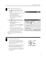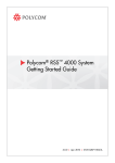
1
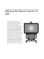
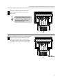
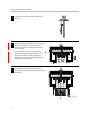
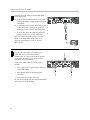
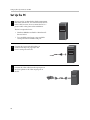
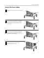
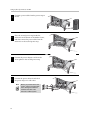
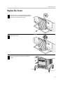
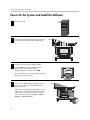
Setting Up the
Polycom® Instructor™ FS HDX
Version 1.5
February 2008 Edition
1725-27077-003/A
Version 1.5
Trademark Information
Polycom®, the Polycom logo design are registered trademarks of Polycom, Inc. and Instructor™ FS HDX is a trademark
of Polycom, Inc. in the United States and various other countries. All other trademarks are the property of their
respective owners.
Patent Information
The accompanying product is protected by one or more U.S. and foreign patents and/or pending patent applications
held by Polycom, Inc.
© 2008 Polycom, Inc. All rights reserved.
Polycom Inc.
4750 Willow Road
Pleasanton, CA 94588-2708
USA
No part of this document may be reproduced or transmitted in any form or by any means, electronic or mechanical, for
any purpose, without the express written permission of Polycom, Inc. Under the law, reproducing includes translating
into another language or format.
As between the parties, Polycom, Inc. retains title to, and ownership of, all proprietary rights with respect to the software
contained within its products. The software is protected by United States copyright laws and international treaty
provision. Therefore, you must treat the software like any other copyrighted material (e.g. a book or sound recording).
Every effort has been made to ensure that the information in this manual is accurate. Polycom, Inc. is not responsible
for printing or clerical errors. Information in this document is subject to change without notice.
About this Guide
This document, Setting Up the Polycom Instructor FS HDX, explains how to
install the various components of the Polycom® Instructor FS™ HDX system,
how to connect the cables, power on the equipment, and perform all the other
steps you need to get the system up and running. This document is intended
for installers who have been trained on how to set up the Instructor FS HDX
equipment.
Because the Polycom Instructor FS HDX contains components from different
manufacturers, you may have to refer to other documents during the set-up
process. This document will describe the steps you need to take and, if
necessary, tell you where to look for additional information.
Most of the other documents that you’ll have to refer to are included with your
Polycom Instructor FS HDX, either as printed documents, available through
the CDs that come with the system, or as online help files. These documents
include:
•
Polycom Polycom Instructor FS HDX Quick Reference
•
Polycom Setting Up the HDX™ 9001/9002 System
•
Polycom Administrator’s Guide for Polycom HDX Systems
•
Polycom User’s Guide for Polycom HDX Systems
•
Polycom Instructor Tools Toolbar online help
•
SMART™ Board Interactive Whiteboard Installation Guide for Flat-Panel
Displays
•
SMART Board software online help
•
Installation and User’s Manual for the display
You can also find most of the Polycom documents at
www.polycom.com/videodocumentation.
For support or service, please contact your Polycom distributor or go to
Polycom Support at www.polycom.com/support.
iii
Setting Up the Polycom Instructor FS HDX
iv
Contents
Setting Up the Polycom Instructor FS HDX . . . . . . . . . . . . . . . . . . . . . . . .1
Unpack the Equipment . . . . . . . . . . . . . . . . . . . . . . . . . . . . . . . . . . . . . . . . . . . . . 2
Set Up the Media Center . . . . . . . . . . . . . . . . . . . . . . . . . . . . . . . . . . . . . . . . . . . 4
Set Up the Flat-Panel Display and the SMART Board Interactive Whiteboard . . . . . . 9
Set Up the Camera . . . . . . . . . . . . . . . . . . . . . . . . . . . . . . . . . . . . . . . . . . . . . . 15
Connect the HDX 9002 and VGA Splitter Cables . . . . . . . . . . . . . . . . . . . . . . . . . 17
Set Up the PC . . . . . . . . . . . . . . . . . . . . . . . . . . . . . . . . . . . . . . . . . . . . . . . . . . 20
Connect the Power Cables . . . . . . . . . . . . . . . . . . . . . . . . . . . . . . . . . . . . . . . . . 21
Replace the Covers . . . . . . . . . . . . . . . . . . . . . . . . . . . . . . . . . . . . . . . . . . . . . . 23
Power On the System and Install the Software . . . . . . . . . . . . . . . . . . . . . . . . . . . 24
Configure and Use the System . . . . . . . . . . . . . . . . . . . . . . . . . . . . . . . . . . . . . . 26
Regulatory and Safety Notices . . . . . . . . . . . . . . . . . . . . . . . . . . . . . . . .29
v
Setting Up the Polycom Instructor FS HDX
vi
Setting Up the Polycom Instructor FS
HDX
The Polycom Instructor FS HDX combines the
power of a Polycom HDX 9002 video
conferencing system with the capabilities of a
SMART Board interactive whiteboard.
With a Polycom Instructor FS HDX, you can
make and receive video calls and share content
just like you would in a typical video conference.
But with the addition of the SMART Board
interactive whiteboard, you can annotate that
content, and you can touch the screen to make
selections from the HDX user interface. For
example, you can jot down notes on a slide
presentation that you’re sharing with the far site,
draw a pie chart on your Windows desktop, or
highlight changes on a file from your computer.
The SMART Board interactive whiteboard
connects to a 50-inch flat-panel display. Both of
these attach to the top of the Polycom Media
Center. The Media Center also houses the HDX
9002 system, it provides stereo speakers so you
can hear audio from your video conference with
added clarity, and it enables you to roll the
system from room to room. To use the Polycom
Instructor FS HDX, you must provide your own
PC.
1
Setting Up the Polycom Instructor FS HDX
Unpack the Equipment
1
Unpack the Polycom equipment.
Camera
cable
Power cable
Audio cable
Speaker wires
Power cable (for HDX)
OUTPUT 2
OUTPUT 1
ON 12V DC
INPUT
Microphone
cables
LAN cable
Audio cable
2
VGA cable (from
VGA splitter to PC)
Power cable
Power adapter cord
VGA cable (from
HDX to VGA splitter)
4-pin mini DIN
S-video cable
9-pin serial cable
S-video-to-BNC
cable
DVI-to-HDMI cable
RGB cable
Power cables
Unpack the Equipment
2
Make sure you have all of the screws and nuts
shown in the illustration.
If you are missing any of the items shown
in step 1 and step 2, contact your Polycom
distributor or go to Polycom Support at
www.polycom.com/support.
M5 x 10 sems Phillips panhead screws
1/4-20 x 5/8 Phillips flathead screws
M8 x 20 button head cap screws
M3 Phillips flathead screws
Mounting nuts
1/4-20 x .75L flathead screws
Wing nuts
3
Unpack the flat-panel display and
associated equipment, and unpack the
SMART Board interactive whiteboard and
associated equipment.
•
The flat-panel display comes with a remote
control and batteries, which you will need
later in the installation process. At this point,
simply insert the batteries into the remote
control.
•
The SMART Board interactive whiteboard
comes with the pen tray, software, the
SMART Board mounting kit, and other items
you will need later in the installation process.
For more information about these items, refer
to the documentation that you received with
the SMART Board.
3
Setting Up the Polycom Instructor FS HDX
Set Up the Media Center
4
1
Lock the wheels on the Polycom Media
Center.
2
Remove the panel from the back of the Media
Center.
3
Attach the speaker wires to the Media Center
speakers.
Set Up the Media Center
4
Place the subwoofer inside the Media Center.
5
Secure the subwoofer to the Media Center by
tightening the captive screws located beneath the
Media Center.
6
Attach the speaker wires to the subwoofer.
5
Setting Up the Polycom Instructor FS HDX
6
7
Place the top on the Media Center.
8
Secure the top to the Media Center using the four
1/4-20 x 5/8 Phillips flathead screws.
9
Remove the rails from inside the Media
Center.
Set Up the Media Center
10
Remove the top shelf from the Media Center.
11
Reinstall the rails you removed in step 9.
12
Attach the mounting ears to the front corners
of the HDX 9002 system.
13
Slide the rack-mount clips onto the top of the
rails.
7
Setting Up the Polycom Instructor FS HDX
Secure the HDX 9002 to the Media Center:
14
a
Slide the HDX 9002 into the top of the
Media Center.
b
For each hole in the mounting ears on the
HDX 9002, push through one of the screws
that came with the ears, and then tighten the
screws.
15
Attach the display support bracket to the top
of the Media Center using six of the M5 x 10
sems Phillips panhead screws.
16
Attach the rail to the display support bracket using
two of the M5 x 10 sems Phillips panhead screws.
8
Set Up the Flat-Panel Display and the SMART Board Interactive Whiteboard
Set Up the Flat-Panel Display and the SMART Board
Interactive Whiteboard
1
Connect the SMART Board interactive whiteboard
to the pen tray. Then, connect the MOD4 cable
that you received with the SMART Board from
the pen tray to the mini RJ-11 socket on the
underside of the SMART Board.
For information on how to do this, refer to the
documentation that you received with the
SMART Board.
2
Place the SMART Board interactive whiteboard
face down on a work bench or table.
Hang the pen tray over the edge of the work
bench or table.
9
Setting Up the Polycom Instructor FS HDX
3
Place the 50-inch flat-panel display facedown onto
the SMART Board interactive whiteboard.
Center the flat-panel display left to right and top
to bottom on the SMART Board.
4
Attach a mounting nut to each mounting
plate using a 1/4-20x.75L flathead screw.
5
Attach the mounting plates to the flat-panel
display using four M8x20 button head cap
screws. Tighten with an allen wrench.
10
Set Up the Flat-Panel Display and the SMART Board Interactive Whiteboard
6
Align the SMART Board mounting bracket
to the mounting plates using four
M8x20 button head cap screws. Do not
tighten the screws at this point.
The SMART Board mounting
bracket is shipped in the SMART Board
mounting kit. For more information about the
SMART Board mounting bracket, refer to the
documentation that you received with the
SMART Board mounting kit.
67
Attach the left and right mounting ears to the
SMART Board mounting bracket using the
four carriage bolts and thumb nuts.
The mounting ears, carriage bolts, and thumb
nuts are shipped in the SMART Board
mounting kit. For more information about
the SMART Board mounting kit, refer to the
documentation that you received with the kit.
78
Secure the SMART Board mounting bracket to
the back of the SMART Board interactive
whiteboard using the two washers and two
mounting handles.
The washers and mounting handles are
shipped in the SMART Board mounting kit.
For more information about the SMART
Board mounting kit, refer to the
documentation that you received with the kit.
Tighten the four M8x20 button head cap
screws using an allen wrench.
11
Setting Up the Polycom Instructor FS HDX
89
180
12
Connect the following cables to the connectors
on the bottom of the flat-panel display.
•
Connect the DVI-to-HDMI cable to the
HDMI connector.
•
Connect the 9-pin serial cable to the
RS-232 connector.
•
Connect the RGB cable to the RGB IN
connector.
•
Connect the 4-pin mini DIN S-video cable
to the S-video connector and then connect
the other end of this cable to the S-video
connector on the S-video-to-BNC cable.
•
Connect the power cable to the power
connector.
Attach the flat-panel display and
SMART Board to the Media Center by
aligning the mounting nuts on the monitor
brackets to the key hole slots in the cross rail.
Set Up the Flat-Panel Display and the SMART Board Interactive Whiteboard
11
Route the cables through the holes in the
display support bracket as shown in the
illustration.
Note
12
The 9-pin serial cable connects to the
PC. Depending on where you locate the
PC, you may or may not want to route
this cable through the holes in the
display support bracket.
The SMART Board interactive whiteboard ships
with two power cables. Connect these two
cables to each other. Then, route the cable
through the holes in the back of the display
support bracket as shown in the illustration.
13
Setting Up the Polycom Instructor FS HDX
13
14
Connect the 2.1 mm female end of the power
cable that you routed in the previous step to the
power connector on the back bottom of the SMART
Board (behind the display support bracket).
For information on how to do this, refer to the
documentation that you received with the
SMART Board interactive whiteboard.
Do not connect the power cable to a power outlet
at this point in the installation.
14
Set Up the Camera
Set Up the Camera
1
Remove the hardware from the top and bottom
of the camera platform.
2
Place the camera on the camera platform and
secure it with the four camera screws.
3
Attach the camera platform to the camera arm
using the hardware that you removed in step 1.
15
Setting Up the Polycom Instructor FS HDX
4
Connect one end of the camera cable to the
camera.
5
Adjust the camera platform to sit on the top of
the flat-panel display. Attach the camera
arm to the display mounting bracket using
two wing nuts.
Loosen the knob on the camera platform
and adjust the platform against the front of
the flat-panel display. There should be a
small amount of space between the platform
and the front of the display.
6
16
Route the camera cable through the holes
in the display support bracket as shown in the
illustration.
Connect the HDX 9002 and VGA Splitter Cables
Connect the HDX 9002 and VGA Splitter Cables
1
Connect the camera cable to the Camera 1
connector on the HDX 9002.
For more information about how to connect
cables to the HDX 9002 system, refer to the
Polycom Administrator’s Guide for Polycom
HDX Systems.
Y
1
Y
C
2
Y
C
3
VCR/DVD
C
PC CARD
1
IOIOIO
2
3
Y
4
C
VCR/DVD
100-240VAC 50/60Hz 4A
1
1
3
1
VCR/DVD
3
VCR/DVD
IR
LAN
2
Connect the following cables to the HDX 9002:
a
Connect both BNC ends of the
S-video-to-BNC cable (that you connected in
step 8 on page 12) to the Monitor 2 output
connector on the HDX 9002.
b
Connect the DVI-to-HDMI cable (that you
connected in step 8 on page 12) to the
Monitor 1 output connector on the HDX
9002.
Y
1
Y
C
2
Y
C
3
VCR/DVD
C
PC CARD
IOIOIO
1
2
3
Y
VCR/DVD
C
4
100-240VAC 50/60Hz 4A
1
1
3
VCR/DVD
1
3
VCR/DVD
IR
LAN
For more information about how to connect
cables to the HDX 9002 system, refer to the
Polycom Administrator’s Guide for Polycom
HDX Systems.
17
Setting Up the Polycom Instructor FS HDX
3
Connect the audio cables from the HDX 9002
to the subwoofer:
a
b
c
Connect the two Phoenix ends of one audio a
cable to the Audio 1 output connectors on the
b
HDX 9002.
c
Connect the red and white RCA ends of this
d
audio cable to the corresponding red and
white RCA ends of the second audio cable.
e
Connect the other end of the second audio
f
cable to connector A on the subwoofer.
1
Y
2
Y
C
3
Y
C
VCR/DVD
C
PC CARD
1
IOIOIO
2
3
Y
4
C
VCR/DVD
100-240VAC 50/60Hz 4A
1
1
3
1
VCR/DVD
3
VCR/DVD
IR
LAN
For more information about how to connect
cables to the HDX 9002 system, refer to the
Polycom Administrator’s Guide for Polycom
HDX Systems.
4
Connect the other cables you need for your
HDX 9002 system as described in the
Administrator’s Guide for Polycom HDX Systems
or the Polycom Setting up the Polycom HDX
9001/9002 System documents.
Some of the other cables you must connect
include:
Y
1
Y
C
2
VGA cable to the Camera 4 input connector
on the HDX 9002.
•
Microphone cables to the microphone
connector.
•
LAN cable to the LAN connector.
Do not connect the power cable for the HDX 9002
at this point in the installation.
18
3
VCR/DVD
C
PC CARD
IOIOIO
1
2
3
Y
VCR/DVD
C
4
100-240VAC 50/60Hz 4A
1
1
•
Y
C
3
VCR/DVD
1
3
VCR/DVD
IR
LAN
Connect the HDX 9002 and VGA Splitter Cables
5
Connect the following cables to the VGA splitter:
a
Connect the VGA cable from the display
to the Output 2 port on the splitter.
b
Connect the VGA cable from the
Camera 4 input connector on the HDX
9002 to the Output 1 port on the splitter.
Once the cables are connected, attach the Velcro
to the bottom of the VGA splitter and then stick
the VGA splitter onto the upper shelf inside the
Media Center.
6
Connect the power cable for the VGA
splitter into the power connector on the
splitter, and then connect that power cable
to the power adapter cord.
OUTPUT 2
OUTPUT 1
ON 12V DC
INPUT
OUTPUT 2
OUTPUT 1
ON 12V DC
INPUT
Do not connect the power adapter cord to
a power outlet at this point in the installation.
19
Setting Up the Polycom Instructor FS HDX
Set Up the PC
1
Set up your PC as described in the documentation
that came with the PC. You should connect the PC
to the LAN; however, do not connect the PC to a
power outlet at this point in the installation.
The PC is required to have:
2
3
•
Windows 2000 Service Pack 3 or Windows XP
Service Pack 2
•
Two available serial ports or one available
serial port and an available USB port
Connect the 9-pin serial cable (that you
connected in step 8 on page 12) to the
Com 1 serial port on the PC.
Connect the VGA cable from the input port on
the VGA splitter to the VGA output port on
the PC.
OUTPUT 2
OUTPUT 1
ON 12V DC
INPUT
20
Connect the Power Cables
Connect the Power Cables
1
Place a power strip at the bottom of the Media
Center.
2
Connect the power cable (that you connected in
step 8 on page 12) from the power connector
on the bottom of the flat-panel display to the
power strip.
3
Connect the power cable (that you connected in
step 11 on page 13) from the power connector
on the bottom of the SMART Board interactive
whiteboard to the power strip.
3
VCR/DVD
1
1
VGA
VGA 2
LAN
3
VCR/DVD
1
1
2
VGA
IOIOIO
PC CARD
2
2
VGA 2
LAN
3
VCR/DVD
1
1
2
VGA
IOIOIO
PC CARD
2
2
VGA 2
1
LAN
C
Y
2
C
Y
IOIOIO
4
PC CARD
2
2
Y
Connect the HDX power cable from the
HDX 9002 to the power strip.
2
IOIOIO
1
1
3
VCR/DVD
3
2
VCR/DVD
3
VCR/DVD
C
1
Y
3
VCR/DVD
1
C 1
4
2
1
PC CARD
VGA
2
PC CARD
VGA
1
3
IOIOIO
IOIOIO
PC CARD
2
VCR/DVD
1
3
100-240VAC
2
2
2
VCR/DVD
VGA 2
IR
LAN
VGA 2
50/60Hz
4A
LAN
LAN
21
Setting Up the Polycom Instructor FS HDX
5
Connect a power cable from the power strip to
the PC.
3
VCR/DVD
1
1
2
VGA
IOIOIO
PC CARD
2
2
VGA 2
LAN
3
VCR/DVD
1
1
2
PC CARD
VGA
IOIOIO
2
2
6
VGA 2
Place the second power strip beside the
subwoofer at the bottom of the Media Center,
and then connect the power cable from the
subwoofer to the second power strip.
LAN
3
VCR/DVD
1
1
2
VGA
IOIOIO
7
Connect the power adapter cord from the
VGA splitter to the second power strip.
8
Connect the power cables from both of
the power strips to a wall outlet.
PC CARD
2
2
VGA 2
LAN
3
VCR/DVD
Note
22
Before you proceed to the next
section, use the provided cable
ties to arrange the cables as
needed in the back of the
Instructor FS HDX system.
1
1
2
VGA
IOIOIO
PC CARD
2
2
VGA 2
LAN
Replace the Covers
Replace the Covers
1
Place the cover on the display support bracket
and insert an M5 x 10 sems Phillips panhead
screw into each of the three holes.
2
Tighten the screws.
3
Replace the panel on the back of the Media
Center.
3
VCR/DVD
1
1
2
VGA
IOIOIO
PC CARD
2
2
VGA 2
LAN
23
Setting Up the Polycom Instructor FS HDX
Power On the System and Install the Software
1
2
3
Power on the PC.
Power on the flat-panel display by pressing the
button on the back left corner of the display.
Set the PC’s resolution to 1024x768 60Hz.
Press the AV button on the Sampo remote
control that you received with the
flat-panel display, and then select RGB.
This will enable you to use the Sampo flat-panel
display as the PC’s monitor.
4
Power on the HDX 9002 by flipping down the
flap on the front of the system and pressing
the power button.
Take note of the IP address that appears on the
home screen of the HDX 9002 system. If the IP
address does not appear on the home screen,
you can find it by going to System > Admin
Settings > LAN Properties.
24
Power On the System and Install the Software
5
Install the Polycom Instructor Tools software on
the PC.
The Polycom Instructor Tools software is on the
Polycom CD. Insert the CD into the PC and then
follow the setup wizard.
6
Install the SMART Board software on the PC.
The SMART Board software is on the SMART
CD. Insert the CD into the PC and then follow the
setup wizard.
Note
When setting up the SMART Board
software, do not change the Display
Control Settings in the SMART Board
Settings dialog box that you access
from the SMART control panel.
SMART
25
Setting Up the Polycom Instructor FS HDX
Configure and Use the System
1
Press the AV button on the Sampo remote
control that you received with the
flat-panel display, and then select HDMI.
This will enable you to complete the HDX setup
wizard using the Polycom remote control.
Note
In the HDX setup wizard, make sure
you set the Monitor 1 setting to DVI
1280x720 60Hz.
For information about using the Polycom remote
control, refer to the User’s Guide for Polycom HDX
Systems. For information about the setup wizard,
refer to the Administrator’s Guide for Polycom HDX
Systems.
2
Press the AV button on the Sampo remote.
Calibrate the touch screen for the SMART
Board interactive whiteboard.
For information about how to calibrate the
SMART Board, refer to the documentation that
you received with the SMART Board interactive
whiteboard.
3
Configure the HDX 9002 system by following
the instructions in the Administrator’s Guide for
Polycom HDX Systems.
product pic here
Administrator’s Guide
for Polycom HDX Systems
Version 1.0.1
December 2006 Edition
3725-23977-002/A
Version 1.0.1
26
Configure and Use the System
4
Configure the Polycom Instructor Tools:
a
Press
on the Polycom Instructor Tools
toolbar, select Connect to HDX, and do the
following:
— Enter the IP address and the password (if
needed) for the HDX 9002.
— Select the Connect button.
— Check that the status on the Instructor
Tools toolbar says “Connected to
Polycom HDX”.
b
Press
on the Polycom Instructor Tools
toolbar again, select Display Configuration,
and do the following:
— In the Display Model field, select
Sampo 50 PDP.
— In the COM Port field, select COM1 (the
port used by your PC to connect to the
display).
— In the Use PIP field, check the box.
— In the Toolbar Dock field, select whether
you want the Instructor Tools toolbar to
appear at the top or bottom of the screen.
For more information about the Polycom
Instructor Tools, refer to the Instructor Tools
online help.
5
Use the Instructor FS HDX system.
•
For basic information about the common
tasks you can perform using the Instructor FS
HDX system, refer to the Polycom Instructor
FS HDX Quick Reference.
•
For instructions on using the Polycom HDX
9002 video conferencing system, refer to the
User’s Guide for Polycom HDX Systems.
•
For information related to the SMART Board
interactive whiteboard, refer to the SMART
documentation.
27
Setting Up the Polycom Instructor FS HDX
28
Regulatory and Safety Notices
For regulatory information about the Polycom Instructor FS HDX, refer to the
documentation for the specific Instructor FS HDX component. For example,
for the Polycom HDX 9002, the SMART Board interactive whiteboard, the
Sampo flat-panel display, and the VGA splitter, regulatory information is
available on the hardcopy documents or through the CDs shipped with the
Instructor FS HDX. You can also obtain regulatory information about Polycom
components on the Polycom web site, www.polycom.com. For other
components, such as the PC, refer to the documentation for your particular
components.
Industry Canada (IC)
This Class [A] digital apparatus complies with Canadian ICES-003.
Cet appareil numerique de la Classe [A] est conforme à la norme NMB-003 du
Canada.
The Industry Canada label identifies certified equipment. This certification means
that the equipment meets telecommunications network protective, operational and
safety requirements as prescribed in the appropriate Terminal Equipment Technical
Requirements document(s). The Department does not guarantee the equipment will
operate to the user's satisfaction
29
Setting Up the Polycom Instructor FS HDX
Important Safeguards
Read and understand the following instructions before using the system:
•
Close supervision is necessary when the system is used by or near children. Do
not leave unattended while in use.
•
Only use electrical extension cords with a current rating at least equal to that of
the system.
•
Always disconnect the system from power before cleaning and servicing and
when not in use.
•
Do not spray liquids directly onto the system when cleaning. Always apply the
liquid first to a static free cloth.
•
Do not immerse the system in any liquid or place any liquids on it.
•
Do not disassemble this system. To reduce the risk of shock and to maintain the
warranty on the system, a qualified technician must perform service or repair
work.
•
Connect this appliance to a grounded outlet.
•
Only connect the system to surge protected power outlets.
•
Keep ventilation openings free of any obstructions.
SAVE THESE INSTRUCTIONS.
30