1
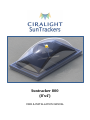
Suntracker 800 (8’x4’) USER & INSTALLATION MANUAL TABLE OF CONTENTS Manual …………………………………………………………………………………….. Thank You ……………………………………………………………………... Disclosure ……………………………………………………………………... Product Parts ………………………………………………………………… Tools Required ……………………………………………………………… Safety Issues …………………………………………………………………. Cutting Holes & Building Curbs ………………………………………………… Template for Roof Openings ………………………………………….. Building the Curb ………………………………………………………….. Attaching Curb to Roof ………………………………………………….. Installation ……………………………………………………………………………… Lightwell Assembly ………………………………………………………. Dome Frame Assembly …………………………………………………. Attach Post to Post ……………………………………………………….. Triple Mirror Array & GPS Controller Assembly …………….. Dome …………………………………………………………………………… User Manual .......................................................................................................... Troubleshooting ……………………………………………………………………... Ciralight Global Inc. | 670 E. Parkridge Ave, #112, Corona, CA, 92879 | (877) 520-5005 | www.ciralight.com 2 THANK YOU To whom it may concern, Thank you for your purchase of our energy-saving Ciralight Suntracker. Upon installation of these Active Daylighting skylights, your building will immediately become more energy efficient, will harness abundant, natural sunlight, and will enhance the human experience of all who work or live beneath them. Your support of Green building practices through the use of Active Daylighting technologies is sure to inspire a higher standard for Sustainable Architecture, Construction, and Property Management while also setting the example that future generations will follow. From all of us here at Ciralight Global and all those who will benefit from the natural lighting provided by Ciralight SunTrackers in your building; Thank you. Jeff Brain CEO, Ciralight Global Inc. Ciralight Global Inc. | 670 E. Parkridge Ave, #112, Corona, CA, 92879 | (877) 520-5005 | www.ciralight.com 3 WARRANTY DISCLOSURE Ciralight’s responsibility for any loss or damage ends, and title passes, when products are delivered to the carrier, to Customer, or to Customer’s agent (including, without limitation, any test house, value added service provider, or contractor), whichever occurs first. Ciralight warrants those products manufactured, assembled or customized by it against defects caused by manufacturing, faulty assembly or customization for ten (10) years after delivery. All other products, and the components and materials utilized in any assembled or customized products, are covered by, and subject to, the terms, conditions, and limitations of the manufacturer’s standard warranty, which warranty is expressly in lieu of any other warranty, express or implied, for by Ciralight or manufacturer. Customer’s exclusive remedy, if any, under these warranties is limited, at Ciralight’s election, to any one of (a) repair by Ciralight or the manufacturer of any products found to be defective, or (b) replacement of any such product. Products are deemed to be accepted by Customer unless Customer notifies Ciralight in writing within ten (10) days of delivery of product shortages, damages, or defect. No returns may be made for any reason without a Return Authorization Form issued by Ciralight. If Customer refuses to accept tender or delivery of any products or returns any products without authorization from Ciralight, such products will be held by Ciralight awaiting Customer’s instruction for 20 days, after which date Ciralight may deem the products abandoned and dispose of them as it sees fit, without crediting Customer’s account. Neither Ciralight nor its suppliers will have any liability or obligation to Customer or any other person for any claim, loss, damage, or expense caused in the whole or in part, directly or indirectly, by the inadequacy of any products for any purpose, by any deficiency or defect in any product (whether or not covered by any warranty), by the use or performance of any products or by any failure or delay in Ciralight’s performance hereunder, or for any special, direct, indirect, incidental, consequential, exemplary or punitive damages, however caused, including, without limitation, personal injury or loss of business or profit, whether or not Customer will have informed Ciralight of the possibility or likelihood of any such damages. Customer expressly agrees, as a material condition of Ciralight selling the Product to Customer, not to disassemble or break the seal on the GPS Controller or any sealed or hidden portion of the Product, or to decompile, or otherwise reverse engineer, or attempt to reverse engineer, the Product in whole or in part, or derive the technology, operating system or computer program from all or any portion of the Product or permit or encourage any third party to do any of these activities. The warranty for the Controller shall become voided if the seal of the GPS Controller unit is broken for any reason. Ciralight Global Inc. | 670 E. Parkridge Ave, #112, Corona, CA, 92879 | (877) 520-5005 | www.ciralight.com 4 PRODUCT PARTS Parts for each SunTracker 800 Qty. 1 1 1 1 1 1 Product Parts Plastic Dome Aluminum Dome Frame 1 Dome Frame Retainer 1 Crossbar (installed at Factory) 2 Top Diffusion Lens (installed at Factory) 1 Bolt (installed at Factory) Dome Frame Screws 24 #8 - 5/8 inch Self Tapping Stainless Steel Screw Solar Tracking GPS Controller Box 1 Solar Tracking GPS Controller (Yellow) 2 Plastic Thumb Nuts Triple Mirror System 3 Mirrors (Large, Medium and Small) 1 Mirror Bracket 1 Vertical Mirror Post (14”) 3 Lock Pins (1/16” x 2”) Small Bottle of Loctite Lightwell Assembly 2 Long Lightwell Side Panels 2 Short Lightwell Side Panels 2 “L” Crossbraces for middle support 4 Corner Angle Braces Lightwell Screws #8 - 5/8 inch Self Tapping Stainless Steel Screw 32 For 24 Inch Lightwell 48 For 36 Inch Lightwell 56 For 48 Inch Lightwell 72 For 60 Inch Lightwell Lightwell - Foam Insulation Tape Single-Sided Options/Info Acrylic or Polycarbonate To secure Dome Frame Retainer to Dome Frame To secure vertical Mirror Post Lightwell Lengths vary 98” x Varying Height 48” x Varying Height 48” Varying Height To seal Lightwell corners Flat, Pyramid and Low Ceiling in Acrylic or Polycarbonate 2 Bottom Diffuser Lens 1 Silicone Sealant Tube 16 Curb Screws 10-32 x 1 ¾ Phil Pan M/S 18-8 Stainless Steel Screw To Secure Dome Frame to Curb 1 Curb - Foam Insulation Tape Single-Sided Placed on parameter of Lightwell top under Dome Frame Ciralight Global Inc. | 670 E. Parkridge Ave, #112, Corona, CA, 92879 | (877) 520-5005 | www.ciralight.com 5 TOOLS REQUIRED Power Drill o ¼” Hex Bit o 5/8” Hex Bit o Philips Screw Bit Adjustable Wrench Compass Caulking Gun SAFETY ISSUES When on a roof installing Ciralight SunTrackers, a few safety precautions to keep in mind include: Regardless of flat or sloped roof, harness yourself with an authorized Roof Fall Protection kit; which includes a harness, rope, and the necessary braces and screws Closed toed shoes with sufficient grip should be worn at all times Gloves and Kneepads are recommended, but not required Beware of high winds when installing the Ciralight SunTracker as its large surface area can be caught by a strong breeze and blown from the roof and damaged or possibly hurt others below Be careful when standing over the roof extrusion or un-domed Dome Frame, as you can fall through and into the building interior below Ciralight Global Inc. | 670 E. Parkridge Ave, #112, Corona, CA, 92879 | (877) 520-5005 | www.ciralight.com 6 CUTTING HOLES & PREPARING CURBS To determine roof location of skylight curbings, consult architects drawings and proceed. Before cutting or drilling through a roof, it is the responsibility of the contractor to ensure that there are no obstructions above or below the roof (drawings provided on following pages). Step 1) From the underside of the roof, locate the first bay (area between trusses) that will contain SunTrackers. Locate the position of the first SunTracker within this bay by measuring off the nearest adjacent wall. The exact center of the SunTracker should be positioned along a center line between the trusses. Drill your first hole here completely through the roof. Step 2) At the opposite end of the same bay, find the center of the last SunTracker in this row (keeping uniform spacing between each SunTracker). Drill your second hole here completely through the roof. Step 3) From on top of roof, snap a chalk line between the two drilled holes. This will establish the center line for all SunTracker in this row (and will keep them centered between the trusses below). Repeat this process in each bay that is to contain SunTrackers. Step 4) You can now proceed with cutting the holes in the roof (making and using a 48” x 96” template can be very helpful). Step 5) Cut away (soft) existing roofing material and install curbing directly on a hard surface. Step 6) The finished curb must be securely fastened to the roof. See details for suggested methods regarding metal, wood, or concrete roofs. Step 7) New flashing and waterproofing to the roof shall be done following accepted practices and consistent with existing conditions. Step 8) Contractor will provide a temporary watertight cover to remain in place until SunTracker installation is made. TEMPLATE FOR ROOF OPENINGS Before roof cuts are made, Contractor will determine if additional reinforcement is required & indicate same on installation drawing. 24.375” 24.375” Ciralight Global Inc. | 670 E. Parkridge Ave, #112, Corona, CA, 92879 | (877) 520-5005 | www.ciralight.com 7 BUILDING THE CURB Step 1) Use (nominal) 98.25” & 50.25” quality pressure treated lumber as needed. Step 2) Curbs must be raised 8” minimum. Step 3) Top of the curbs must be level and plum all the way to the bottom of the light well. Step 4) All corners must be square. Step 5) Curb should measure 108.34” across the inside diagonal (inside corner to inside corner). 99.75” OUTSIDE 51.75” 48.75” 96.75” INSIDE Opening 96.75” x 48.75” cut and remove existing roof inside curb On a slanted roof, the low side of the curb will need to be taller than the high side so as to maintain a level top to the installed curb. Metal curb can be substituted for wood. 99.75” 8” Curb (min.) 96.75” Curb Roof Lightwell Truss Blocking Drop Ceiling Lower Diffuser Lenses Ciralight Global Inc. | 670 E. Parkridge Ave, #112, Corona, CA, 92879 | (877) 520-5005 | www.ciralight.com 8 ATTACHING CURB TO ROOF Securely fasten curb(s) to the roof bracing structure to give it strength and support for the SunTracker unit (Dome, Dome Frame, Lightwell, and Lenses). Maintain top of Curb true plumb and level; top surface to be smoothed Typical (4) sides new wood curbs cut from 2x8 or larger Cricket (if required) Flashing (4) sides up to 1” from top of Curb If under roof blocking is used, secure curbing (to new blocking) w/ 1.25” galv. strapping; min. (2) each side Attaching Options for Different Roof Types If roof curbs require additional reinforcing at any opening, such details will be indicated by original roofer and must be signed off by building owner. 1) METAL ROOF Pre-drill pilot holes from underneath the deck and attach the curb using 3” - #10 Hex head screws. 2) WOOD ROOF Toe-nail new curbing to existing wood. If under-roof wood blocking is used, install 9” or 12” galvanized strapping. 3) CONCRETE ROOF Must use pressure treated lumber (or prefab sheet metal) for curbs. Use small clip angles fastened with expansion bolts to anchor curbs to concrete. Attachment of curbs should meet all building codes and requirements. Ciralight Global Inc. | 670 E. Parkridge Ave, #112, Corona, CA, 92879 | (877) 520-5005 | www.ciralight.com 9 SUNTRACKER 800 INSTALLATION Ciralight Global Inc. | 670 E. Parkridge Ave, #112, Corona, CA, 92879 | (877) 520-5005 | www.ciralight.com 10 Before beginning the installation, we recommend you put the GPS Controllers out in the sun to charge and do NOT press the rest button until the Controller is fully charged (4 hours in the sun; 6 hours in cloudy weather). LIGHTWELL ASSEMBLY Step 1) Remove the protective film from each LIGHTWELL Panel’s reflective side. Step 2) Run single-sided INSULATING FOAM TAPE from top to bottom along both Inside Edges of the four (4) CORNER BRACES. Step 3) Arrange a Dry-Fit of the LIGHTWELL assembly using the two (2) LONG LIGHTWELL Panels, two (2) SHORT LIGHTWELL Panels, and four (4) CORNER BRACES. a. Make sure the Outward Flange (1.5”) is at the top and the Inward Flange (2”) is at the bottom. b. Place a CORNER BRACE on the outside of each Vertical Corner Edge of the four (4) adjacent LIGHTWELL Panels. c. Make sure all LIGHTWELL Panels and CORNER BRACES are even from top to bottom before screwing Panels together. Step 4) Screw LIGHTWELL Panels together through the FOAM TAPE of each CORNER BRACE into each LIGHTWELL Panel. a. Place a screw within 2” of the top and the bottom, then one screw every 8” in between from top to bottom. b. Use 8 x ¾” Hex Washer/ Self-Drilling Screw. Step 5) Repeat for all four (4) LIGHTWELL edges. Step 6) Put together the LIGHTWELL CROSSBRACE. a. Put both “L” BRACES back-to-back alongside the shorter edge so that the longer edges lie flat. b. Place four (4) Screws through the back-to-back “L” BRACES along the length of the CROSSBRACE to connect them together. Step 7) Install the LIGHTWELL CROSSBRACE. a. Turn the LIGHTWELL upside-down (Outer Flanges on the ground; Inner Flanges on top). b. Place the Flat Edge of the CROSSBRACE inside the LIGHTWELL onto the Inner Flange halfway along the LONG LIGHTWELL length (48” from the ends) and screw two (2) Screws through the bottom of the Inner Flange and into the CROSSBRACE on each end of the CROSSBRACE. c. Flip the LIGHTWELL over again, right-side up (Outer Flanges on top; Inner Flanges on bottom). Step 8) Apply SILICONE SEALANT to all eight (8) sides of the Bottom, Inner Flange of the assembled LIGHTWELL. Ciralight Global Inc. | 670 E. Parkridge Ave, #112, Corona, CA, 92879 | (877) 520-5005 | www.ciralight.com 11 Step 9) Gently lower one (1) BOTTOM DIFFUSER LENS down into the bottom of each side of the LIGHTWELL and press the edges of the DIFFUSER LENS into the SEALANT. a. LIGHTWELL will have two (2) BOTTOM DIFFUSER LENSES in all. b. If this is a PYRAMID BOTTOM DIFFUSER LENS, the Pyramid’s point will face down. c. For longer LIGHTWELLS, it is recommended that the BOTTOM DIFFUSER LENSES be put into place from within the building after the LIGHTWELL is in place upon the Curb. Step 10) With the BOTTOM DIFFUSER LENSES secure, lift the assembled LIGHTWELL up over the Curb and gently slide it down into the building interior. a. The Top, Outer-facing Flanges of the LIGHTWELL should sit flush upon the top of the Curb all the way around. Step 11) Apply FOAM TAPE to the perimeter of the top of all four (4) Top, Outward-facing Flanges of the LIGHTWELL around the entire Curb (24’ in all), with the adhesive side down on the Flanges. DOME FRAME ASSEMBLY Step 1) Place DOME FRAME down upon the Curb. a. Make sure the DOME FRAME sits level on the Curb before moving to the next step. Step 2) Screw the DOME FRAME to the Curb using the pre-fabricated holes on each of the four (4) sides of the FRAME as guides. a. Use 10-32 x 1 ¾ Phil Pan M/S 18-8 Stainless Steel Screws [included]. ATTACH POST TO CROSSBAR Proper installation of the Post is one of the most critical parts of the Suntracker installation. If the Post is not correctly installed, the Suntracker will not work to its full potential. The Flat side of the D-Cut hole in the top of the post MUST face “True South.” This portion of the Installation is critical. It is recommended you read instructions first, then begin installation of the Post to the Crossbar. Step 1) Step 2) Afix POST to the DOME FRAME CROSSBAR. Vertical Post -- a. BOLT and two (2) NUTS come pre-assembled from the factory on the DOME FRAME CROSSBAR. b. Apply a few drops of LOCTITE to threads of the BOLT and inside the bottom threads of the POST. c. Screw the POST down onto the BOLT almost all the way down; within 1/8” of the lowest NUT. Crossbar Position the D-Cut Hole at the top of the POST towards True South. Lock Washer - -- Lock Washer -- Bolt Ciralight Global Inc. | 670 E. Parkridge Ave, #112, Corona, CA, 92879 | (877) 520-5005 | www.ciralight.com 12 a. Adjust the POST until the Flat Side of the D-Shape hole in the POST is perpendicular to True Flat Side of South. i. Make sure to use True South; NOT Magnetic South. ii. You can use a compass and adjust the calculation based on your location or, with the use of a Smartphone, can download a free-app that will locate True South for you. Digital applications will vary by service provider. Step 3) Post’s D-Cut must face “True South” Once the POST is facing the correct direction, securely hold it in place and, with one hand, tighten the NUT closest to the POST until the POST is firmly fastened from below. TRIPLE MIRROR ARRAY & GPS CONTROLLER ASSEMBLY Note: Do NOT press the Reset Button on the GPS Controller until the unit is fully charged (approximately 4 hours in sun; 6 hours in cloudy weather). The reset button is not required during installation. Once fully charged, the unit will begin operating automatically and will start tracking the sun on its own. Step 1) Remove the protective film from each MIRROR’S reflective side. Step 2) Take the MIRROR BRACKET and hold so the Short Curved Portion faces downward. Step 3) Attach the Largest-sized MIRROR to the end of the MIRROR BRACKET’S Flat Portion by aligning the MIRROR’S Brace to BRACKET’S pre-fabricated holes and putting a LOCK PIN through the MIRROR’s Brace and the MIRROR BRACKET. a. The Largest-sized MIRROR’S reflective side should face towards the MIRROR BRACKET’S center cut hole. Step 4) Attach the Medium-sized MIRROR to the center of the MIRROR BRACKET and the Smallestsized MIRROR to the MIRROR BRACKET’S Curved End by putting a LOCK PIN through each MIRROR’S Brace and the BRACKET. a. The Medium-sized and Smallest-sized MIRROR’S reflective sides should face the same direction as the Largest-sized MIRROR. Step 5) Take the GPS CONTROLLER and slide it’s three (3) Posts through the top of the MIRROR BRACKET’S center three (3) pre-fabricated holes. Ciralight Global Inc. | 670 E. Parkridge Ave, #112, Corona, CA, 92879 | (877) 520-5005 | www.ciralight.com 13 a. Position the Solar Panel of the GPS CONTROLLER toward the Small MIRROR. Step 6) Secure the GPS CONTROLLER to the MIRROR BRACKET by tightening one (1) THUMB SCREW to each of the Screw Posts protruding from the bottom of the GPS CONTROLLER. Step 7) Take the entire TRIPLE MIRROR ARRAY (Mirrors, Bracket, GPS) and slide the D-Shaped GPS Post inside the D-Shaped Hole at the top of the POST. a. With the TRIPLE MIRROR ARRAY, slide the POST through the hole in the Middle-sized MIRROR before placing the ARRAY upon the POST. Step 8) Gently rotate the MIRROR ARRAY until the Solar-Panel of the GPS CONTROLLER faces the sun. a. Do not leave the installed MIRROR ARRAY unattended long without the DOME placed over it. Wind can cause the MIRROR ARRAY to spin out of control and can cause damage to the MIRRORS and Solar Tracking of the GPS CONTROLLER. DOME Step 1) Remove the FRAME RETAINER CAP from the DOME FRAME and place the Plastic DOME onto the DOME FRAME. a. The edges of the Plastic DOME should be parallel and evenly distributed over the WeatherStripping of the FRAME. Be sure the edges extend beyond the Weather-Stripping on each side. Step 2) Place a line of SILICONE SEALANT approximately a ½” from the DOME’S edge around the entire DOME. Step 3) Re-place the FRAME RETAINER CAP over the outer perimeter of the DOME and FRAME. a. Press the top of the FRAME RETAINER CAP down along the entire edge of the DOME to assure a firm seal with the SILICONE. Step 4) Screw the FRAME RETAINER CAP down to the DOME FRAME. a. Apply force down on the FRAME RETAINER CAP while screwing. b. Use four (4) 8 x ¾” Hex Washer/ Self Drilling Screws on each of the two (2) Short Sides of DOME FRAME and eight (8) 8 x ¾” Hex Washer/ Self Drilling Screws on each of the two (2) Long Sides of the FRAME RETAINER CAP. c. Screw through the Middle etching along all four (4) outer sides of the FRAME RETAINER CAP into the DOME FRAME. Ciralight Global Inc. | 670 E. Parkridge Ave, #112, Corona, CA, 92879 | (877) 520-5005 | www.ciralight.com 14 USER MANUAL Upon Installation - Do not press the Reset Button on the GPS Controller until the Controller is fully charged (4 hours in the sun; 6+ hours on overcast days). If you press the button, you may compromise the tracking ability of the GPS Controller. - Make sure the GPS Controller is tracking the Sun o Mirror and Solar Panel (on GPS) should face the sun o If they do not: Make sure the flat-edge cut into the top of the Post is perpendicular to True South If the post is correct, press and hold the reset button for 5 seconds (upon which you should hear a beep) and allow the unit 5 minutes to reset its GPS calculations and adjust itself to the proper location o If this does not work, consult Ciralight Global Seasonal Maintenance - Make sure the GPS Controller is tracking the Sun o If not, please consult the Troubleshooting area of the Installation Manual Check that the Dome is clean and unobstructed o If dirty, rinse off with water (as needed) and a soft cloth Do NOT use a paper towel or paper material as it may scratch the plastic of the Dome o If covered with snow, we recommend that you do not go onto the roof to remove the snow (as it may be dangerous). The heat trapped within the unit should be enough to melt the snow quickly. Ciralight Global Inc. | 670 E. Parkridge Ave, #112, Corona, CA, 92879 | (877) 520-5005 | www.ciralight.com 15 TROUBLESHOOTING TOPICS 1) Low Light Levels 2) Dome Frame Doesn’t Rest on the Curb 3) GPS Not Turning 4) Weather-Proofing 5) Dirt/ Debris Inside Suntracker 6) Water Collection in Dome Frame 7) Mirror Hitting Inside of Dome 8) Bent/ Curved Single Mirror 9) Bottom Diffuser Lens Doesn’t Sit in Lightwell 10) Crossbar & Screws Rusting 1) Low Light Levels o Dome: o If dirty and needs immediate attention, clean with water and let air dry o If covered with snow, allow to melt away. It is not recommended to remove snow from up on roof as conditions may be dangerous o Mirrors: o Mirror’s reflective surface may not be facing the sun; if not, turn Mirror(s) around and re-secure o GPS: o If turning: But not facing the Sun, check to see the Post is facing “True” South; NOT “Magnetic” Press and hold the reset button for 5 seconds, then allow five minutes for GPS to reprogram itself automatically o Dome Frame: o Remove debris/dirt from Top Diffuser Lens, then check Sponges and Weather-Stripping to ensure future protection from outdoor elements (see “Weather-Proofing: Dome Frame” for details) 2) Dome Frame Doesn’t Rest on Curb o Curb: o Size of Curb not proper for Dome Frame; must resize Curb and reflash for proper installation 3) GPS Not Turning Ciralight Global Inc. | 670 E. Parkridge Ave, #112, Corona, CA, 92879 | (877) 520-5005 | www.ciralight.com 16 o GPS: o May not be charged; allow for 15 minutes of direct sunlight and observe If this is immediately after installing the GPS unit, give the GPS Controller one (1) full day to charge before deeming unit ineffective o Check to make sure the Bolt and Post are tightly affixed to the Crossbar. If loose, the Post begins to spin with the GPS Controller o Press and hold the reset button for 5 seconds, then allow five minutes for GPS to reprogram itself automatically in direct sunlight o Possible Broken GPS Controller; consult product warranty o Post: o Check that the Post, Bolt, and Washer haven’t loosened. If so, tighten and make sure the post faces True South 4) Weather-Proofing o Dome: o Make sure Dome is evenly centered over the Dome Frame’s Weather-Stripping and also under the Dome Frame Retainer o Dome Frame Retainer should be pressed firmly down when screwing to the Dome Frame. If not, this could cause gaps/space between Dome, Dome Frame, and Dome Frame Retainer o Dome Frame: o Check that Silicone Sealant is applied correctly between the Dome Frame Retainer and Dome o Check that the Weather-Stripping is properly in place between the Dome and the Dome Frame o Make sure the Sponges are present and positioned correctly (pointing towards the center) o Be sure that the Mid-Tray Lens is thoroughly Sealed with Silicone Sealant around the edges and that no gaps are present o Curb: o Check that Flashing goes up to within 1” of the top of the Curb 5) Dirt/Debris Inside Suntracker o Dome Frame: o Check that Sponges, Weather-Stripping, and Silicone Sealant are all present and properly placed (see “Weather-Proofing: Dome Frame” for details) o Dome: o Dome Frame Retainer should be pressed firmly down when screwing to Mid-Tray. If not, could cause gaps/space between Dome, Dome Frame, and Dome Frame Retainer 6) Water Collection in Dome Frame o Curb: Ciralight Global Inc. | 670 E. Parkridge Ave, #112, Corona, CA, 92879 | (877) 520-5005 | www.ciralight.com 17 o o Curb should allow for level positioning of Dome Frame Dome Frame: o Sponges should point to center of unit, not outward, to allow movement of water out of runoff 7) Mirror Hitting Inside of Dome o Curb: o Curb must be level for proper functioning o Dome: o Dome may not be level; possibly due to missing Weather-Stripping on Dome Frame o Dome may not be centered on Dome Frame; must be centered and even over the Weather-Stripping and under the Frame Retainer Cap o Crossbar: o May not be centered over Dome Frame; re-position Crossbar 8) Bent/Curved Single Mirror o Mirror Bracket: o If Single Mirror Bracket Extension isn’t used, Mirror may not be properly fortified and could deform slightly. Newer units do not receive Extensions as it is already built in 9) Bottom Lens Doesn’t Sit in Lightwell o Curb: o Curb may be too big, thus Lightwell opening is too large o Lightwell: o Each piece of Lightwell should overlap the Vertical Flanges over the Straight Edges and hold into place; if reversed, pieces will be loose o Lightwell construct should be square and flush at each edge 10)Crossbar & Screws Rusting o Crossbar: o Some units have been refurbished from a previous ‘hang-down’ version to include a crossbar made from steel, not aluminum like the rest of the skylight, which may rust Ciralight Global Inc. | 670 E. Parkridge Ave, #112, Corona, CA, 92879 | (877) 520-5005 | www.ciralight.com 18