1
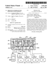
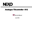
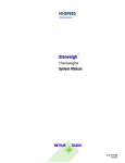
Installation and operation guide Crystalline solar modules For specialists en User manual for Bosch Solar Module products c-Si M60+ S EU56117 and c-Si M60+ EU56117 Issue 11/2013 2 | Contents | Introduction en Contents 1Introduction 2 2 Safety instructions 3 3 Positioning guidelines 4 4 Installation guidelines 5 5 Circuitry guidelines 12 6 Electrical connection 12 7 Grounding and lightning protection 13 8 Maintenance and care 14 9 Disposal15 10 Transport and storage 15 1 Introduction Please read these installation and operating instructions only be carried out by specialists, such as electricians, completely and carefully before you transport, install who have demonstrated that they have suitable training. and operate the solar modules. They contain important safety information which you must become familiar with. These installation and operating instructions only apply If these solar modules are used without observing all to the following products with Module Manufacturer the instructions in this document, any warranty or gua- Code 17: rantee claims against us are voided. We reserve the right to update any information contained in this document Bosch Solar Module c-Si M 60+ S without prior notification if this is required from a tech- Bosch Solar Modules c-Si M 60+ nical point of view or if it represents an extension of application opportunities for the end customer. Only the installation and user manual from 11/2013 is valid for Bosch solar modules of the above named A high degree of specialist knowledge and experience is series. required to assemble and install solar modules and put them into operation. For this reason, such work should Bosch Solar Module c-Si M60+ S EU56117 I Bosch Solar Module c-Si M60+ EU56117 Bosch Solar Energ AG en Safety instructions | 3 2 Safety instructions Damaged solar modules, such as those Electrical installation work and initial operation may only with broken glass or damage to the rear be carried out by a qualified electrician in observance of side insulating foil, must not be installed. the following instructions, since incorrect installation Damage to the rear side insulating foil can may lead to damage or injury. Suitable safety precau- have severe consequences (delamination, tions, such as fall-arrest systems, must be in place when health and life-threatening hazards). working on solar generators, particularly on rooftops. You must comply with employers' liability insurance association regulations on work safety. Please observe Mount the solar module in such a way that it is not the following safety instructions for your own safety and effected by shade (even temporary of partial shade to protect your solar module: caused by dormers, trees or similar obstacles) since this may lead to damage in the solar module (e.g. Important note! such as formation of hot spots and resulting fire hazard), PV generator failure or losses in performance. Connecting modules in series (addition of module voltages) can generate voltages above the safety extra-low voltage of 120 V DC. The pertinent regulations and safety information Disconnecting lines carrying direct current may cause concerning the installation of electrical equipment electric arcs. It is therefore essential to disconnect and systems and the electricity provider’s regulations the inverter from the AC network before beginning on the operation of solar power systems in parallel any type of work on solar power systems, especially mains operations must be taken into account when before disconnecting plug connections from the DC installing and servicing solar modules. Guidelines on fires in electrical systems apply (e.g. VDI 3819). The modules have been classified for Application Class A: Dangerous voltage (IEC 61730: 50 V, EN circuit. If systems are installed on roofs, the modules must be mounted above a fire resistant subsurface. Solar modules must not be installed near easily flammable substances, gases or vapors. 61730: greater than 120 V). Even in poor light conditions, modules can be expected to carry a full open-circuit voltage. Consequently, Warning! this means extreme care must be taken to prevent The maximum permissible total system electrical faults, such as short circuits, when install- voltage of the inverter must never be ing modules. exceeded. Solar modules should be handled in the same way as glass products and you must never place objects such To do so, the open-circuit voltage of the overall sys- as tool boxes on their surface or tread on them when tem must also be calculated at the minimum permis- they are in their shipping container or when they are sible temperature due to the negative temperature installed. coefficient of the solar modules (see data sheet and The solar modules must be checked to be in perfect mechanical integrity before their installation. module label). The modules and module frames must never be drilled, nailed, stuck with adhesive or welded. Bosch Solar Module c-Si M60+ S EU56117 I Bosch Solar Module c-Si M60+ EU56117 Bosch Solar Energy AG english Warning! 4 | Safety instructions | Positioning guidelines en relevant specialist publications. You can calculate the Warning! inclination angle using the following formula: inclina- Do not use connection cables or the tion angle = latitude of installation location – 20°. junction box to hold or carry solar modules. Important note! All modules in a photovoltaic generator should be positioned at the same angle Warning! (both horizontally and vertically). Sepa- The module must not be trodden on, rate MPP trackers (inverters) are to be under no circumstances. provided if modules are not positioned at the same angle. Solar modules must never be left in a free-standing or unsecured position. The inclination angle must be at least 10° to ensure The safety instructions provided by the manufacturers self-cleaning is effective. A minimum inclination angle of the other components in the solar power system of 15° is recommended to optimize self-cleaning and must always be followed. air convection. Bosch Solar modules meet the building regulation list requirements for PV modules having a maximum glass Make sure that rear of the module is well ventilated. Modules must be mounted so that the rear of the surface of by 2 m² as established by the DIBt module does not come into contact with objects (Deutsches Institut für Bautechnik, [German Institute behind it, even if a mechanical load is applied, e.g. for Building Technology]). cables and parts of the substructure. Minimum clearance from building edges according to Important note! In Germany the installation of a solar module on a roof area having a slope e.g. DIN EN 1991-1-4 Eurocode 1 must be taken into account to prevent increased stress on modules due to wind load. When arranging modules in open field systems, suit- angle > 75° requires a general technical able measures must be taken to ensure that readily approval. ignited organic materials (e.g. dry grass, hay) are regularly removed from the vicinity of the system. 3 Positioning guidelines We recommend a module installation which fulfills the following requirements to ensure the highest annual energy yield possible: Mount the solar module in such a way that it is not Important note! Prerequisite to installation on a flat roof is a hard roofing seal per DIN 4102, Parts 4 and 7 – if there is uncertainty about the roofing surface, please ask your roofer. effected by shade (even temporary of partial shade caused by dormers, trees or similar obstacles) since this may lead to damage in the solar module (e.g. such as formation of hot spots and resulting fire hazard), PV generator failure or losses in performance. Position the front of the solar module, so that it faces the Equator. Select the inclination angle according to local conditions and structure type (30° ± 15°). You can obtain Warning! Due to heat accumulation under the modules there is an increased fire hazard associated with rooftop installations which do not meet the aforementioned requirements. detailed information on optimum module installation in Bosch Solar Module c-Si M60+ S EU56117 I Bosch Solar Module c-Si M60+ EU56117 Bosch Solar Energ AG Positioning guidelines | Installation guidelines | 5 en Mount the modules on an adequately dimensioned, It is forbidden to use mirrors or lenses to The installation profiles are to be positioned in parallel to one another. concentrate sunlight on modules. The fastening points are to be aligned symmetrically (see Figure 1). The solar module can be attached with clamps, lay-in Important note! systems or, alternatively, directly to the assembly Ensure modules do not come into con- holes. If clamp systems are used, the clamp contact tact with saltwater. surface must be at least 400 mm² for each fastening point. Furthermore, under all conditions, the surface area must be min. 400 mm² for each fastening point. The crystalline solar modules by Bosch Solar Energy have been successfully tested for their contact with Important note! salty air according to the following standards: • IEC 61701: 1995 Ensure you use the fastening sections as • DIN EN 61701: 2000-08 indicated in tables 2 to 5. • IEC 60068-2-52. Please note the test conditions given in the use of mod- Ensure that the mounting holes are correctly positi- ules in salty air. oned as in Figures 2 and 4 when fitting the module using mounting holes. You are also to use four corrosion resistant screws and nuts as per Table 1 and washers with a minimum outside diameter of 12 mm 4 Installation guidelines Mount the solar module in such a way that it is not effected by shade (even temporary of partial shade caused by dormers, trees or similar obstacles) since and a maximum of 14 mm. Module Manufacturer Code Screw diameter 17 M6 Table 1: Permissible fastening screws for direct installation this may lead to damage in the solar module (e.g. such as formation of hot spots and resulting fire hazard), PV generator failure or losses in performance. When using clamps or direct attachment at the assembly holes, the modules must be fastened flush to the substructure at at least four points under as little stress and tension as possible. Important note! The solar module must be installed under as little Take into account additional loads pro- mechanical stress as possible and at a minimum duced by the PV system's weight and distance of 5 mm from the next module to allow for structural mount when carrying out the any expansion in materials resulting from temperature structural analysis for the overall struc- fluctuations. ture. The supporting structure or substructure must be adequately dimensioned based on a structural analysis and adapted to the environmental conditions The system installer or operator must provide an locally to ensure that the maximum permissible de- analysis of the building structure's stability, deflec- flection or deformation on the long side of the mod- tion and loads. ule under a load of max. 4 mm is not exceeded. For the short side, there is a max. value of 2 mm. You also Bosch Solar Module c-Si M60+ S EU56117 I Bosch Solar Module c-Si M60+ EU56117 Bosch Solar Energy AG english permanently corrosion resistant, stable substructure. Warning! 6 | Installation guidelines en need to ensure that the module does not distort or warp more than 10 mm across its diagonal line. Only Warning! one of the named deformations is permissible in this. The solar module must not stand in condensation or stagnant water. Important note! The substructure and solar module must have the same thermal expansion coefficient (e.g. aluminum). Ensure contact corrosion between the solar module and substructure is prevented when different materials are used. Fasten the solar modules in such a way that they are able to withstand all anticipated loads and any impacts caused by weather conditions. Use only corrosion resistant screws to install modules. Important note! Figure 1: Permissible layout of the fastening points and installation profiles Solar modules must always be installed in such a way that the cable inlets in the junction box face downwards or sideways. Ensure the support structure does not allow rainwater or condensation water to reach the cable screw connections in the junction box. Bosch Solar Module c-Si M60+ S EU56117 I Bosch Solar Module c-Si M60+ EU56117 Bosch Solar Energ AG en Installation guidelines | 7 Vertical fastening sections for Bosch Solar Module c-Si M60+ S EU56117 (with crossbar) Pressure load rating to 3900 N/m² Pressure load rating from 3900 N/m² to 5400 N/m² Pressure load rating up to 7200 N/m² 150 150 150 150 80 30 80 30 80 30 150 80 80 30 30 150 350 350 350 350 150_ 150_ 150_ 150_ 80 30 150_ 350_ 350_ 80 30 350_ 350_ 350_ 150_ 350_ 30 30 30 300 300 30 80 30 30 30 80 80 30 80 Slide-in and lay-in system3 30 80 80 80 substructure below crossbar 30 300 30 80 80 300 80 300 30 80 300 300 300 300300 300 300300 300 80 300300 300 300300 300 30 80 30 80 80 30 80 30 80 30 350 200_ 300 300 200_ 300 substructure below crossbar 350 350 200_ 200_ 300 substructure below crossbar 350 Fastener clamp system on300short 300300 300 300 300 sides2 300 300 500 300 300 200_ 350 350 350 200_ 350 200_ 500 500 500 500 500 500 500 500 500 500 500 500 500 300 300 350 200_ 200_ 350 200_ 200_ 350 350 350 350 500 500 500 500 500 500 500 500 500 Fastener clamp system on long sides1, 2 500 200_ Screw fastening to assembly holes substructure below crossbar Table 2: Vertical fastening sections for Bosch Solar Module c-Si M60+ S EU56117 (with crossbar) Consider the position of the crossbar when using a center support. Position the support, so that it holds up the module crossbar. centre support line center clamping range junction box The clamp contact surface must be at least 400 mm² for each fastening point. Furthermore, under all conditions, the surface area must be min. 400 mm² for each fastening point. 2 The clamping sections are also valid for the use of concealed clamping on the surrounding assembly groove (see p. 12). 3 Please additionally note the information on installation of the module with lay-in and slide-in systems on p. 11. 1 Bosch Solar Module c-Si M60+ S EU56117 I Bosch Solar Module c-Si M60+ EU56117 Bosch Solar Energy AG english Consider that the module crossbar is not in the middle of the module. See Figure 2 for details. 8 | Installation guidelines en Horizontal fastening sections for Bosch Solar Module c-Si M60+ S EU56117 (with crossbar) Consider that the module crossbar is not in the middle of the module. See Figure 2 for details. Pressure load rating to 3900 N/m² Pressure load rating from 3900 N/m² to 5400 N/m² Pressure load rating up to 7200 N/m² Screw fastening to assembly holes Fastener clamp system on long sides4, 5 350 350 200_ 500 200 substructure below crossbar 500 substructure below crossbar 300 substructure below crossbar 300 Fastener clamp system on short sides5 Slide-in and lay-in system6 substructure below crossbar Table 3: Horizontal fastening sections for Bosch Solar Module c-Si M60+ S EU56117 (with crossbar) Consider the position of the crossbar when using a center support. Position the support, so that it holds up the module crossbar. centre center line support clamping range junction box The clamp contact surface must be at least 400 mm² for each fastening point. Furthermore, under all conditions, the surface area must be min. 400 mm² for each fastening point. 5 The clamping sections are also valid for the use of concealed clamping on the surrounding assembly groove (see p. 12). 6 Please additionally note the information on installation of the module with lay-in and slide-in systems on p. 11. 4 Bosch Solar Module c-Si M60+ S EU56117 I Bosch Solar Module c-Si M60+ EU56117 Bosch Solar Energ AG en Installation guidelines | 9 Pressure load rating ≤ 2400 Pa Pressure load rating ≤ 5400 Pa Pressure load rating ≤ 5400 Pa Without center support With center support Fastener clamp system on short sides 400 400 125_ 25_ 400 400 400 400 200 200 200 400 400 400 400 400 400 200 200 200 200 400 200 400 360 360 360 360 360 360 400 400 400 400 360 360 360 360 440 360 440440 440 440 440 440 440 500 500 500 440 440 440 440 440 300 300 300 300 300 300 300 300 360 360 360 360 360 440 440440 500 500 500 500 500 500 500 500 500 500 Fastener clamp system on long sides 500 500 500 Screw fastening to assembly holes 300 300 300 300 300 300 300 300 Slide-in or lay-in system Slide-in or lay-in system Table 4: Vertical attachment section for Bosch Solar Module c-Si M60+ EU56117 When positioning the center support, ensure that it lies above the junction box. center support clamping range junction box Please additionally note the information on installation of the module with lay-in and slide-in systems on p. 11. The clamping sections are also valid for the use of concealed clamping on the surrounding assembly groove (see p. 12). Bosch Solar Module c-Si M60+ S EU56117 I Bosch Solar Module c-Si M60+ EU56117 Bosch Solar Energy AG english Vertical fastening section for Bosch Solar Module c-Si M60+ EU56117 10 | Installation guidelines en Horizontal fastening section for Bosch Solar Module c-Si M60+ EU56117 Pressure load rating ≤ 2400 Pa Pressure load rating ≤ 5400 Pa Pressure load rating ≤ 5400 Pa Without center support With center support Screw fastening to assembly holes 440 440 500 Fastener clamp system on long sides 500 440 360 440 440 360 440 360 440 360 440 400 200 400 360 440 360 360 440 400 200 400 200 360 360 400 200 400 500 500 500 500 360 440 360 440 500 500 500 500 440 360 440 360 360 440 500 500 500 500 500 500 360 360 440 400 400 200 400 200 400 400 200 400 400 _25 400 200 400 300 300 300 300 400 400 300 300 300 300 300 300 300300 300300 300 Fastener clamp system on short sides 300 400 _125 Slide-in or lay-in system Slide-in or lay-in system Table 5: Horizontal attachment section for Bosch Solar Module c-Si M60+ EU56117 When positioning the center support, ensure that it lies above the junction box. center support clamping range junction box Please additionally note the information on installation of the module with lay-in and slide-in systems on p. 11. The clamping sections are also valid for the use of concealed clamping on the surrounding assembly groove (see p. 12). Bosch Solar Module c-Si M60+ S EU56117 I Bosch Solar Module c-Si M60+ EU56117 Bosch Solar Energ AG en Installation guidelines | 11 The draining function of the module corners for the frame profile must al288 ±2 ways be ensured. If necessary, additional draining opportunities should be put in place in the mounting system. +2 777 - 10 grounding mounting When using a lay-in system or the corner clamps for mounting the module, the draining function of the drainage corners (and therefore the cleaning function) 1674 ±2 35 centre line crossbar centre line module can be limited. 0,5 0,1 ±0 grounding ,5 4,3 6± 288 ±2 (-) 800+50 7± 7 (+) 1200+50 990 ±2 mounting MAßSTAB 1 : 10 1674 ±2 Figure 2: Rear Bosch Solar Module c-Si M60+ S EU56117 (-) 800 +50 Bearing area on frame: The frame must be covered on the upper side by at least 5 mm and no more than 12 mm (a). The slide-in or lay-in system must overlap the under- mounting side by at least 3 mm and have a surface area of at least 2 mm width (b). grounding long frame part 5<x<12 4,3 6± 0,1 118 ±2 the following should be observed (see Figure 3): (+) 1200 +50 When fastening modules with slide-in or lay-in systems, short frame part 5<x<12 a Figure 4: Rear Bosch Solar Module c-Si M60+ EU56117 When fastening modules in the area of the module or drainage corners, the following should be observed (see Figure 5): If corner clamps are used, a minimum cover area of 28 mm of the clamp must be ensured (length of the assembly clamp). 1<x<22 b 2<x 1<x<7 The assembly clamp must overlie by min. 8 mm and 2<x max. 12 mm on the frame (depth of assembly clamp). Figure 3: Permitted contact areas in slide-in and lay-in systems Bosch Solar Module c-Si M60+ S EU56117 I Bosch Solar Module c-Si M60+ EU56117 Bosch Solar Energy AG english Important note! 118 ±2 990 ±2 12 | Installation guidelines | Circuitry guidelines | Electrical connection en 5 Circuitry guidelines 8≤x≤ 12 28≤x You may only interconnect identical solar modules of the 28≤x ≤ same type and the same power class. Ensure that the maximum permissible system voltage is not exceeded when you connect the modules in series. In doing so, take into account the effect of variations in temperature on the voltage in solar modules, particularly since module voltage Ansicht vorn, Detail Frontvon view detail Drainage-Ecke drainage area increases at low temperatures. When connecting modules in parallel, make sure that each line connected in parallel contains the same number of modules and that suitable measures are in place to protect against power surges (e.g. line fuse). Make certain that the Figure 5: Fastening of the modules in the area of module or drain- indicated load capacity regarding the reverse current IR, as age corners stated in the datasheet, is not exceeded. Alternatively, the module can also be attached to the A PV module may supply a higher current and/or a higher surrounding assembly groove by using the covered clamp- voltage under normal conditions than under standar- ing with the innovative Bosch mini-clamp. The clamp areas dized test conditions. As a result the Isc and Uoc values and assumed loads are valid the same as for mounting of on the module should be multiplied by a safety factor of the module with clamp system (see Tables 2 to 5). 1.25 to determine the rated voltages of components, the rated current in cables, the sizes of fuses and sizing of controls which are connected to the output of the PV modules. Ensure that you comply with local applicable standards and regulations. 6 Electrical connection The solar modules are designed for use in grid-connected solar generators. If they are used for any other purposes, differing technical features should be taken into account. Solar modules may only be installed by qualified specialists. In the process, they must comply with the relevant industrial standards and regulations for PV systems, such as the German Association for Electrical, Figure 6: Additional mounting possibility of covered clamping on Electronic & Information Technologies regulations, DIN surrounding assembly groove standards, German Association of Energy and Water Industries guidelines, the network operator's technical connection conditions and employers' liability insurance associations' accident prevention rules. We draw your attention again to the following points in particular: Bosch Solar Module c-Si M60+ S EU56117 I Bosch Solar Module c-Si M60+ EU56117 Bosch Solar Energ AG Electrical connection | Grounding | 13 en The connection cables should be installed in such a way that the minimum bend radius of 60 mm is complied with. The connection cables are equipped with a high-quality plug system (original MC4) for photovoltaics which latch on if correctly connected. The plugs are Only install non-damaged modules with clean, dry cabling, plug connectors and junction boxes. The solar modules, particularly the plug connectors and tools, must remain dry during installation. Disconnection devices must be fitted between the marked with their respective polarity symbols (see datasheet). Ensure the polarity symbols are in the right position when connecting plug connectors and modules and when connecting solar modules to the inverter. Incor- module and inverter. The disconnect component rect polarity can permanently damage all technologi- must be readily accessible in order to disconnect the cal components in the system. direct current side if danger should arise. Make sure that all electrical connections are properly secured. All solar module frames and the support structure must feature highly conductive connections to a protective grounding system to eliminate the risk of Only use cabling which is suitable for outdoor instal- electric shocks. We recommend installing the ground- lation to interconnect module strings (UV and ozone- ing system outside the building. Observe local statu- resistant, temperature resistance at least between tory regulations and recommendations given by the - 40° C and 110° C). inverter manufacturer and your insurance company. Cables must feature a minimum cross-section of 4 mm² and isolation must be approved for the maxiImportant note! mum system open-circuit voltage. Never remove or insert plug-in contacts Protect cabling against damage by such means as when the system is under load! suitable fastening with cable clips. Important note! Connecting cables which are able to move can lead to chafed points, thus causing insulation damage to the connecting cable. 7 Grounding and lightning protection It is recommended to provide adequate lightning protec- The cables must be laid in such a way that the cables tion, especially in exposed locations. You must comply are not squashed or put under pressure in any other with local applicable standards and regulations when way. integrating modules into existing lightning protection You must not open the junction box with pre-assem- systems. bled, connected cables. The junction box, cabling and connection plug must not be cleaned or dampened with substances con- Important note! taining grease or alcohol. Solar plugs pre-fitted in the factory must not be removed. Ensure that the module connection cable is relieved of strain when installed. Please observe the country-specific standards and regulations when grounding. Bosch Solar Module c-Si M60+ S EU56117 I Bosch Solar Module c-Si M60+ EU56117 Bosch Solar Energy AG english Important note! 14 | Grounding | Maintenance and care en Please implement the following measures for the Functional grounding grounding system (you will find the respective mounting Isolated operation of the modules is recommended, this holes for the grounding system on the rear of the mod- means neither plus nor minus terminal of the module ule frame): have an electrically charged connection to the ground. For the installation of a fitting ring terminal, use a thread grooving screw (DIN7500-1, minimum diameter 5 mm), a self-cutting lock washer, a snap ring Important note! and the right nut. If a functional grounding is required, then this can only be undertaken on the Damaging contact corrosion can be avoided by using minus terminal in the PV system. corrosion-resistant materials. Position of the mounting holes for grounding according to Figures 2 and 4. There is an additional grounding opportunity in the module corners. Use the grounding of a thread grooving screw M5 according to DIN7500-1 and attach it from the rear side of the module behind the plastic 8 Maintenance and care corner. See Figure 7. Little maintenance and care is required to deliver optimum solar module performance. We recommend the following items are checked or the following action Rear view detailed drainage area with a grounding function taken on a half-yearly basis to ensure optimum system performance: If modules are heavily soiled or dirty in places, from bird droppings, for instance, it is recommended to clean module glass surfaces with a soft brush and lime-free water at module temperature. Do not use aggressive cleaning agents, acids or alkaline solutions. Under no circumstances should there be increased pressure during cleaning e.g. by pressing a brush so strongly during cleaning, that this can lead to damage to the antireflective coating of the glass for example. In the case of intensive soiling, repeated cleaning or soaking is recommended. Any finger prints on the anti-reflection solar glass can be removed with a microfiber cloth and distilled water or isopropanol. Figure 7: Grounding possibilities on the module with detailed illustration of module corner Check electrical and mechanical connections to ensure they are clean, tightly fastened and intact. Any anomalies must be remedied immediately. The operator is recommended to check the system's output on a regular basis. The grass and weeds in and around open ground area systems must be mowed regularly. This is necessary to minimize the potential hazard of organic material (e.g. dry grass, hay) combustion in the vicinity of the system. Bosch Solar Module c-Si M60+ S EU56117 I Bosch Solar Module c-Si M60+ EU56117 Bosch Solar Energ AG Disposal | Transport and storage | 15 en Stacking packaging units may lead to damage and must be avoided. Secure solar modules, so that they don't tip over. Padding should be used between individual solar Important note! modules. Defective or old solar modules should be disposed of in the correct manner. They We recommend storing all solar modules in their original must not be thrown away with house- packaging in a dry interior space until they are finally hold waste. installed. Modules being transported must be packaged securely in accordance with local and European requirements. 10 Transport and storage The original packaging should be used wherever possible. Avoid damaging modules in any way when putting them Modules must be handled with great care. Care is re- down or carrying them to their installation location (e.g. quired when unpacking, transporting or storing modules roof). temporarily: Use more than one single part of the frame to hold modules when transporting them. Important note! If you have any questions on the instruction and operating guidelines, please contact our technical support at [email protected]. Set modules down gently without knocking them when placing them on hard ground or on their corners. Avoid bending modules when transporting or unpacking them. Do not drop modules. Do not place any objects on top of modules. Do not use sharp objects to work on modules. Ensure that each module is adequately supported during storage or transportation. Issue 11/2013 Bosch Solar Module c-Si M60+ S EU56117 I Bosch Solar Module c-Si M60+ EU56117 Bosch Solar Energy AG english 9 Disposal Bosch Solar Energy AG Robert-Bosch-Strasse 1 99310 Arnstadt, Germany Germany Tel.: + 49 (0) 3628 66 44-0 Fax: + 49 (0) 3628 66 44-1133 www.bosch-solarenergy.com