1
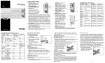
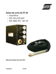
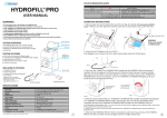
I n s t r u c t i o n m a n ua l
Model MGD-2002
Multi Gas Leak Detector
M o d e l M G D - 2 0 0 2 L e a k Lo cato r
I B - 4 1 7 R e v. G Pa r t N o . 8 4 6 7 1
User Safety Warnings
IMPORTANT: Before operating the device for the first time, read all
of the following safety guidelines. To prevent personal injury, property
damage, or damage to the detector, operate it only in accordance with
these safety guidelines.
• Do not operate the device if it has been damaged. Contact SPX
Radiodetection for advice.
• Do not allow any part of this device to come in contact with an energized high voltage source. Injury or death may result.
• Do not disassemble the device as it will void your warranty. Repairs
should only be performed by qualified factory service personnel.
• Do not allow the Detector to draw up water. Water will adversely
affect the device's operation and will cause internal damage. Water
found inside the unit will void your warranty.
• Take sensible precautions to prevent the ingress of moisture when
using the detector in rain, snow or other adverse conditions. Although
the detector is somewhat water resistant, it is not waterproof. Do not
allow water to accumulate on the detector faceplate, as it could migrate into the electronics.
• Do not use the probe tip to dig in the soil, or use it in any manner
other than as directed in this manual.
• Although this device will operate with a low battery voltage, do not
operate the detector when the battery indicator displays 1/4 battery
or less. False readings may occur when operated under this condition. Refer to pages 7 through 9 for instructions on how to recharge or
replace the battery.
• When charging: This unit should be in an indoor dry location.
• Do Not plug the battery in backwards. Circuit board damage will
result
CAUTION - Refer to accompanying information
i
Table of Contents
Section
Description
Page
User safety warnings
i
Table of contents
ii
1.0
Specifications
1
2.0
List of kit contents
2
3.0
Unpacking your New MGD-2002
3
4.0
Tracer gas
4
4.1 Helium vs Hydrogen as a tracer gas
4.2 Other Gasses the MGD-2002 will react too
5.0
Assembling the MGD-2002 for use
5
6.0
Operation of the MGD-2002
6
6.1 Overview
6.2 Humidity vs Accuracy
6.3 Moisture filter
6.4 Power supplies
6.5 Charging the battery
6.6 Charging the battery using the universal power supply
6.7 Charging the battery from a 12VDC auto adaptor
6.8 Replacing the battery
6.9 Button function and operation
6.10 Liquid crystal display (LCD)
6.11 Display status icon
7.0
Tracer gas leak locating for piping systems
14
8.0
Leak locating for pressurized cables
21
9.0
Serial port (if equiped)
33
10.0 Maintenance
33
11.0 Calibration
35
12.0 Frequently asked questions (FAQ)
36
13.0 Troubleshooting
39
14.0 Service information
40
Warranty
Back cover
ii
1.0 Specifications
Dimensions:
(LxWxD)
Weight:
(MGD-2002 only)
(Shipping)
Temperature Range :
13.3in x 4.9in x 3.3in
(33.7cm x 12.3cm x 8.3cm)
3.1 lbs (1400 grams)
15.0 lbs (6800 grams)
+400F to +800F
(4.40C to +26.60C)
Humidity Range : 20% RH to 50% RH
Sensitivity:
(Min)
(Max)
(Increment)
25 PPM
100% (1,000,000 PPM)
25 PPM (0 to 20,000 PPM)
.1% (2% to 100%)
Tracer gasses :
Resolution:
Helium (He) / Hydrogen (H)
(Low range)
(High Range)
+/- 25 PPM
+/- 0.2 %
Response Time:
15 Seconds (approx.)
Audio Out :
Pulse Width Modulation
LCD:
128 Bit X 64 Bit Dot Matrix
With long-life backlight
Battery:
(Voltage)
(Type)
(Weight)
(Run Time)
(Charging Cycles)
(Charging Volts)
7.2 VDC
Nickel Metal Hydride
383.0 grams
6-8 Hours Continuous
300 - 500
9.5 - 14 VDC @ 2A
Power Supply:
(Charger)
(AC Input)
(DC Output)
110-240V, 1.6A, 60/50Hz
12V, 4.0A
Pump Volume:
1.05 Liters/Min (approx.)
0.85 to 1.00 L/min
.75 to .85 L/min
.60 to .70 L/min
Compliance
CE
1
11
1
2
10
3
9
4
8
5
7
6
2.0 List of kit Contents
Description
1. MGD-2002 gas detector
2. 12VDC Auto Adaptor charger
3. Ground probe with Collection cup
4. Spare moisture filter cartridge
5. Sampling handle
6. Needle probe
7. Battery NiMH
8. Sholder strap
9. Backflush connector
10. 110-240 VAC universal AC charger
11. Carry case
Optional equipment not included
-Headphones
-European power cord
-Serial port
2
Part No.
(79766)
(163-0005-01)
(90664)
(83220)
(83174)
(84165)
(82492)
(300-0012-00)
(84972)
(93642A)
(84672)
(882-0007)
(241-0003-00)
(requires factory installation)
3.0 Unpacking your New MGD-2002.
3.1 Upon delivery
1) Open the shipping package and inspect the MGD-2002 for
any physical damage that may have been caused during
shipping. Keep the packing material in case you ever need to
return the device to SPX Radiodetection.
NOTE: The Manufacturer’s warranty does not cover damage
caused in transit. You must notify your carrier immediately for
any damage claims.
2) Position the device face down to open the battery compartment door. Remove the battery to expose the device information placard. (The serial number is located under the barcode.)
3) Connect the battery plug to the main logic board. Close the
battery compartment door and secure with the quarter turn
fastener.
NOTE: Connecting the battery incorrectly even for a second
will destroy the circuit board.
4) First, plug the universal power supply into a convenient AC
wall outlet then plug the other end into the device.
NOTE: To ensure optimum battery working life, charge battery
for 2 hours before operating the MGD-2002 detector for the
first time. See page 7 for battery charging instructions.
5) Check the moisture cartridge filter and ensure it is blue in
color. Refer to page 34 for filter changing instructions.
6) Before switching the device on, connect either the needle
probe or ground probe to the handle assembly and then connect the handle assembly to the detector using the quick connect fitting on the end of the black tubing. Refer to page 5.
3
4.0 Tracer Gas
4.1 Helium vs. Hydrogen as a tracer gas
The MGD-2002 is a Helium/Hydrogen detector calibrated to detect
“Helium”. However, it will indeed give readings if hydrogen is present.
As this detector is based on the thermal conductivity of gasses and
with Helium and Hydrogen being similar in this regard the detector
will not be able to tell the difference.
Helium is the preferred tracer gas. Helium is a noble gas and does
not react or combine with any other gas or substance. It is safe to
use in all types of leak locating at any concentration up to 100%.
Hydrogen is not generally present in higher quantities in uncontrolled
situations as it is very reactive and if in quantities greater then 4% it
is very flammable and even explosive. To use it as a tracer gas you
need to purchase it mixed to 4% or less with the remainder being
nitrogen. Thus, starting with an already diluted tracer gas making it
that much harder to find as it dilutes even further when you add it to
the system being tested. (not a problem when working with 100%
helium) We certainly DO NOT recommend Hydrogen be used as a
tracer gas for these reasons.
Note: It would take more then 20 tanks of 4% hydrogen mix to equal
the amount of tracable gas in one 100% helium tank. Mixing the
helium down to 4% is certainly an option and can be done by adding
compressed air to the system as it is being filled.
4.2 Other Gases the MGD-2002 will react too
When considering all other gasses there are some that would normally
present false reading when in high concentrations such as CO, CO2
and Ozone (on a busy street) with helium detectors using this above
mentioned sensor type. However, we looked at this situation based
on our experience with older models of our detectors and through the
development of some patented filter media combinations and custom
software we have eliminated or captured these gasses eliminating
the majority of false readings. Unfortunately methane even in very
low concentrations can cause the MGD-2002 to react but this is
generally only seen during certain environmental tests.
4
5.0 Assembling the MGD-2002 for use.
When assembling the device, refer to the List of Kit Contents on
page 2 of this manual.
1. Clip the black sampling tube quick-release connector of the
sampling handle (5) onto the connector on end of the MGD2002 detector (1).
2. Attach either the needle probe (6) or the Ground probe (3):
- To attach the needle probe snap it into the quick connect
coupling of the sampling handle cap/adaptor.
- To attach the ground probe: Unscrew the cap/adaptor
from the sampling handle and screw the sampling handle
into the extendable ground probe (3). Do not overtighten
(Hand tight). Note: applying a small amount of silicone
based lubricant to the seal on both ends of the moisture
cartridge will improve its performance.
3. To extend the ground probe, press the lock button on the
sample probe and with it pressed, gently pull on the sample
collection cup. When the sample probe is at the required
length, release the lock button, ensuring it engages in a
locking position.
4. Turn the MGD-2002 on. The MGD-2002 will perform a self
check and zeroing routine (1 min approx). You are now
ready to look for Helium/Hydrogen
5
6.0 Operation of the MGD-2002
6.1 Overview
The MGD-2002 gas detector is a portable leak-locating and
pinpointing device that can be used in a multitude of pressurized
systems to detect both hydrogen and helium when used as a
tracer gas . Because they are both lighter than air, hydrogen
and helium penetrate small leakage points rapidly. The gasses
permeate through the densest soils and pavements quickly
enabling the leak to be pinpointed easily with the detector.
6.2 Humidity vs Accuracy
The MGD will function correctly at high relative humidity (RH)
levels of 50% or greater, but its accuracy and sensitivity may be
reduced. Lower humidity is prefered.
6.3 Moisture filter
The replaceable moisture cartridge filter removes much of the
moisture from the sample and is designed to enable users to
quickly asses the filter daily life-span by visual inspection. A new
dry cartridge will be bright blue in color, and is shown on page
7. The moisture cartridge will turn pink as it removes moisture
from the air. As it changes color, the filter cartridge is still within
its useful life, but will degrade further to a clear white color if
continually used in high humidity conditions or if water is present.
To maintain optimum filter performance we recommend that you
change it or clear it of moisture when the color changes to light
pink.
The useful life of the filter depends upon the relative humidity
(%RH) of the working environment. For example, on an average
dry day, the %RH is roughly 20%, and in this case the filter should
last between 4-6 hours. If the relative humidity increases to 50%
RH, the single cartridge might last only 2-3 hours. If the humidity
increases to between 50-90% RH, the filter may only last one
hour.
With the MGD-2002 field replaceable system, filters can be
changed within seconds, or cleared and reused within minutes.
Refer to page 34 for instructions on how to change the filter.
6
Spent Cartridge
Dry Cartridge
The internal filtration material has a limited useful life, and SPX
Radiodetection strongly recommends that the MGD is returned for
calibration once a year. During factory recalibration, the moisture
cartridges are cleared or replaced, and other filters have their filtration media changed. Refer to page 35 for a list of all the value-added
benefits that are included in a factory recalibration.
6.4 Power supplies
The MGD-2002 is powered by a replaceable, rechargeable nickel
metal hydride (NiMH) battery and comes supplied with a universal
AC/DC adapter, AC charging lead, and 12 volt DC charging lead
for use with a vehicle cigarette lighter socket.
6.5 Charging the battery
Charging from a completely dead battery will take approx 2 hours
and should last for approximately 6-8 hours of run time. While
charging, the battery will heat up and become warm. As the
sensor is sensitive to temperature changes it will be necessary
to wait approx 20 min for the battery temperature to return to
normal before using the device.
Note: It is not possible to use the MGD-2002 during battery
charging as the detection capability is automatically disabled when the battery charger is plugged in.
Note:The battery is equipped with a temperature sensing
7
element to ensure the battery will not overheat during the
charging cycle. If the ambient temperature is too high, battery charging may shut off prematurely. Ensure that the
MGD-2002 is charged away from any heat sources.
6.6 Charging the battery using the universal power
supply.
1. Plug the AC charging lead into the AC/DC adapter and plug
the other end into a standard power outlet
2. Plug the DC adapter lead into the charging connector located
on the right hand side of the MGD-2002
Note: When the charger is plugged into the MGD-2002 the LCD
will illuminate and display the battery recharging symbol.
Once charging is complete the symbol will change back to a plug
6.7 Charging the battery from a 12VDC auto adapter
1. Plug the auto adapter into the vehicle cigarette light
socket
2. Plug the output jack into the charging connector located
on the right hand side of the MGD-2002.
8
6.8 Replacing the battery
.
Caution - Do not mutilate, puncture, or dispose of batteries by placing them in a fire. The batteries can burst or explode, releasing hazardous chemicals. Discard used batteries
in accordance with the battery manufacturer’s instructions
and your local regulations.
1. Lay the device face down on a flat surface and, using a flat
headed screwdriver, turn the battery cover retaining screw
1/4 of a turn counterclockwise and remove the batteryhousing-cover
2. Lift out the battery and gently pull up the battery connector
lead.
3. Before installing the new battery, attach the three pin connector to the circuit board ensuring it is connected in the
correct orientation.
Note: Connecting the battery incorrectly even for a second
will destroy the circuit board.
4. Ensure that the battery is fitted in the correct position and
that it lies flat in the housing.
5. Install the battery cover taking care to avoid pinching the
wires. Tighten the retaining screw 1/4 turn clockwise.
9
6.9 Button functions and operation
The MGD-2002 features membrane buttons, and has a large multifunction liquid crystal display (LCD). Each button has a raised
embossed edge that is designed to be felt by a user even when
wearing protective gloves. When they are pressed, the buttons
make a noticable “click” that is both felt and heard. The following is
a description of each key on the MGD:
CONTROL
BUTTON DESCRIPTION
(I/O) ON/OFF
The ON/OFF button supplies power to the
device. Once switched on, the device will
initialize, then conduct a 60 second power
on self test (POST).
BACKLIGHT
The light button is used to switch the LCD
backlight on and off. By default the LCD
backlight is turned off to conserve battery
life. When the button is pressed, the backlight will illuminate and will remain on until
the button is pressed again, or the unit is
turned off.
SOUND
The sound button is used to switch the
audio output of the internal speaker on and
off, allowing the operator to listen for the
detection of the tracer gas and not have
to watch the display. By default the audio
output is turned off.
10
PUMP SPEED
Allows manual selection of various pump
speeds to increase accuracy of the sample
reading in situations with very small leaks. At
slower speeds the unit draws in less ambient
air with the sample.
RESET
The Reset button allows the unit to remain
powered up while clearing all the internal
logic circuitry. When the button is pressed,
the device goes through its zeroing routine to
determine a new baseline for future samples.
Using this button to reset the device is
preferred to turning the device off and back on
as it maintains power to the sensing elements,
thus maintaining sensor stability. Only press
this button in a zero tracer gas environment.
A/M
The Mode button controls what is being
displayed on the LCD. By default the unit is set
to automatic mode (A) and will constantly show
what the sensing elements have detected in
both concentration as well as time. If the unit
is placed in manual (M) mode, the device
will continue to draw in samples as normal.
However, when the sample button is pressed,
the LCD no longer shows time, but will only
show what the sensors are detecting at that
particular moment.
SAMPLE
(Only available in manual mode) When the
sample button is pressed, one sample reading is taken. The device calculates the time it
should take for the sample to reach the detector, takes the sample, and then displays the
result. The sample button must be pressed for
every sample needed.
11
6.10 Liquid Crystal Display (LCD)
The LCD is a near real-time display of the tracer gas concentration
the unit has detected. The refresh rate is slightly greater than ten
times every second.
1.11
A
A
A
After the unit is switched on.
This screen will remain displayed
while the processor conducts a
power on self test, which lasts for
approximately 60 seconds.
The LCD displays the aproaching zero symbol upon successful
completion of the power on self
test or when the unit has just
been reset. This display is showing that the unit is setting a zero
point of reference.
The display upon successful
completion of the initial zeroing
routine. This screen will be
displayed until the sensor
elements sense the presence of
a tracer gas. The real time graph
is updated once per second and
shows 60 seconds of history.
12
6.11 Display status icons
There are five small icons shown at the bottom of the LCD screen.
The icon as well as its function is displayed below. The icons are
listed in the order in which they are displayed on the LCD, from left
to right.
NOTE: A function that has been turned off, will have an X
through its icon.
ICON
BATTERY STATUS
This icon gives a visual indicator of the relative lifespan remaining on the battery. When the battery
level drops below 1/4, a warning beep will sound.
The unit will automatically shut off when the empty
battery icon is shown
RECHARGE STATUS
This icon is either displayed, or crossed out. If
the unit is recharging, the icon will change to a
lightning bolt and back to a plug when charging is
complete.
MODE
Shows whether automatic (A) or manual (M) mode
is selected. The default is automatic.
SOUND STATUS
By default the speaker is disabled to conserve
battery power and the speaker symbol will initially
have an X through it. Pressing the speaker button
once removes the X and enables the audio out
circuitry.
PUMP SPEED
Pump speed can be adjusted for use in certain
sampling situation. Pressing repeatedly will slow
the pump until it returns to normal speed.
13
7.0 Tracer gas leak locating for piping systems
7.1 Assumptions:
• You have read and understand all safety information ex
pressed or implied in this MGD-2002 Instruction Manual as
well as your local safety codes and requirements.
• You have pinpointed the location of the system under
ground
• You have emptied the system of liquid
• You are able to inject helium at the low end and provide a
temporary vent at the other end to allow rapid filling.
• You can drill holes in the concrete every 3 feet (1meter) or so
• You are using 100% Helium or 4% Hydrogen as a tracer gas.
7.2 Applicability
This method can be used on any piping system, large or small
that can be emptied and filled with tracer gas. The gas will escape
from the system at the leak and be easily detectable at the surface
of the ground.
7.3 Effects on subscribers
With this method of leak locating the effects on the subscribers is
dependant on the type of system being checked. In the case of
a municipal water or gas system, subscribers should be notified
according to normal procedures. Additionally, on water systems
subscribers along this system should be instructed not to open a
tap during the leak detection process. There is no danger from the
gas but large amounts of tracer gas would be lost. Other system
types may not require any notification.
7.4 Preparing to leak locate
Leak test
Prior to leak locating you must actually determine you have a leak.
Performing a hydrostatic leak test on water systems will confirm
that you have a leak in the piping system and give you an idea
of how big the leak is. Pressurized air systems may show a significant pressure drop or difficulty maintaining desired pressure.
Other systems may require other methods of leak determination.
14
7.5 Locate the system
Locate and mark the piping system path in the projected search
area, noting any recent construction or ground shifting in the area
that may have caused damage to the piping system. (There are
a large variety of pipe/cable locators available from SPX Radiodetection. Please contact SPX Radiodetection sales or customer
service to purchase a locator for your application.)
7.6 Empty the system
In the case of a liquid filled system. Drain the liquid from the system. It is not necessary to have the system completely dry but if
the leak is under liquid the tracer gas will need to push the liquid
out prior to exiting the system. Smaller piping such as heating systems (approx. 1 inch or smaller) may require using the tracer gas
or compressed air to push the liquid out.
Caution - Compressed Gas Contains Energy. Be
careful around pressurized systems: loose parts may
be ejected with high velocity if the pressurized system
bursts.
7.7 Filling the system with tracer gas
Attach the tracer gas. The key words from here on are “Don’t
Rush”. Saturating the ground or the underside of a concrete pad
with tracer gas will make it difficult to pinpoint the leak. The tracer
gas will filter through concrete and pavement “slowly” and this can
cause a plume to build up under the concrete and when it does
come through it will be in a much larger area. In cases where
there is substantial dense material such as concrete or pavement
over the piping system, it may be necessary to drill holes every
two to three feet over the pipe to improve the search results. (For
longer runs of piping with larger leaks under concrete or pavement
every 5-8 feet will narrow the search area.) These holes become
vents and allow for better pinpointing. Systems that are imbedded in concrete will not require holes. However, it will require time
depending on the depth of the concrete.
Keep in mind that the tracer gas is lighter than air and wants to
rise. Start in the lowest point of the system as possible to allow
15
it to go up hill. Additionally, you will need to vent the other end
of the system until tracer gas can be detected at this vent. This
will ensure you that the tracer-gas has reached the leak. Once
detected at the vent, the vent can be closed and the system can
be pressurized with tracer gas. Approximately 3-5 PSI to start but
can be increased safely up to 10% of its normal working pressure
if the leak is not found. (The helium molecule is much smaller
than a water molecule and will exit a leak faster and easier than
water will.) The best approach is to start with lower pressures and
increase slowly. Remember: too much helium to start can make
a leak easy to find (large area) but hard to pinpoint. Also note that
helium will travel in the path of least resistance. (It will find the
easiest path it can, and that path may not be where you would
expect)
Caution - Never pressurize any system above its
working pressure.
7.8 How much tracer gas?
Calculate the volume
Area = π R^2 note Radius (R) in ft
Volume of system (cu ft)
Vsys = Area (sqft X Length (ft)
Example: 500’ of 2” dia pipe
(3.142)(0.084)^2 = 0.022 sq ft
.022 * 500 = 11 cu ft
In this example 11cu ft is the total volume of air inside the pipe.
Note again, it is not necessary to get the pipe to 100% tracer gas
concentration. In most cases 5-10% is adequate for leak locating.
Now lets calculate the volume of air inside the pipe when we
increase the pressure to 5 PSIG. Building upon the previous example:
Total cubic feet required at 5 PSIG
V@ 5PSIG = Vsys * ((14.7 + 5) / 14.7)
16
V@ 5PSIG = 11 * (19.7 / 14.7)
V@ 5PSIG = 14.74 cuft (with no leaks)
At 5 PSIG you would need only 1.47 Cu ft to reach 10% helium in
500ft of 2” dia. pipe with no leaks. In a small system such as this,
building the pressure using the tracer gas is perhaps the easiest way to increase and maintain the pressure while keeping the
tracer gas levels elevated.
A typical tracer gas tank contains 240 standard cubic feet of tracer
gas when full. At a constant flow rate of 30 SCFH, a full tank will
keep adding tracer gas to the system for approximately 8 hours.
240/30 = 8hr
Once the system has been filled and tracer gas is detected at the
vent. Close the vent and begin to build pressure. Continue to add
tracer gas to the system as it will keep the concentration elevated.
7.9 Very large piping system (12” or larger) or tanks
There are additional challenges in larger piping systems and
tanks. Getting enough tracer gas to saturate the system can be a
difficult one. This can be easily accomplished by emptying a full
tank of tracer gas into the system to get the concentration of gas
up rapidly. Then provide additional tracer gas along with compressed air to build the desired pressure. Remember it is not necessary to achieve 100% concentration in the system. That would
be a waste of tracer gas. 5-10% is certainly adequate for leak
locating as the MGD-2002 is capable of reading Helium as low as
25ppm (1%= 10,000ppm).
Another challenge for very large diameter pipe (> 2ft) and tanks
is that it may be necessary to provide some form of air movement
inside the piping system as the tracer gas will want to concentrate
near the top of the pipe. This can be accomplished using a fan
inside the piping to provide mixing.
17
7.10 Estimating charging times
The charging times, pressure used, and the amount of tracer gas
needed are dependent on the size of the pipe and the expanse of
the piping system being tested. Additionally, the size of the leak
and the material over the pipe (loose earth, clay, concrete, pavement, vinyl sheeting) affect the time for the tracer gas to reach
the surface of the ground. Unfortunately with all these variables
it is difficult to determine how long it will take for the tracer gas to
reach the surface of the ground.
7.11 How long to wait
The system is filled with tracer gas and we know that the leak is
allowing tracer gas to rise to the surface. How long this will take
is dependent on several factors such as: the depth of the piping
system, what material (loose earth, clay, concrete, pavement,
vinyl sheeting) is used as backfill and in the way slowing the tracer
gas as it rises to the surface of the ground. (The denser the material the slower the progress of the tracer gas to the surface) It is
virtually impossible to give equations that will help you calculate
the time needed as the conditions in the ground are seldom known
well enough to make calculations useful. Although there are some
basic rules and the majority of cases the waiting time is between
20 min (2-3 feet deep beach sand) and 2 hours (>6 feet deep
gravel) with additional time added for concrete or other dense
materials.
• Materials like vinyl sheeting are non-porous and are very difficult
to permeate and may require holes to allow a measurable amount
of tracer gas to escape
• Thick pavement or concrete may add more than one hour to
waiting time. This extra time can be avoided by drilling holes to allow the tracer gas to vent to the surface.
• The deeper the pipe is buried in the ground the longer it takes to
come to the surface.
• Higher water content in the soil will slow down the gas.
7.12 Leak locating (basics)
The highest concentration of tracer gas will be along the system
path with the highest reading directly over the leak. However
cracks in concrete or pavement and differences in material density
18
(soil) will allow the gas to escape more readily in those areas. A
concentration of gas found several inches away from the marked
system is due to the gas taking the path of least resistance. But is
an indicator that you are getting close. The tracer gas will rise from
the leak in most soil materials in an inverted cone shape. When
it reaches a denser material such as concrete it will slow its upward travel and spread (plume) thus too much Helium too fast can
make pinpointing more difficult.
7.13 Preparing the MGD-2002 detector.
Assemble the black tube of the foam covered handle to the control unit, attach the ground probe (yellow stick) to the handle. Turn
the detector ON and allow it to complete its 60 sec self-test. The
detector should now read “0”. Using the detector at its default settings is best for this type of leak locating. Changing pump speed or
using manual mode is not recommended in this situation.
7.14 Looking for the leak
Start at the tracer gas feed point and begin to survey the system
by placing the rubber cup at the end of the ground probe directly
on the ground over the system and allow a few seconds (15-20)
for the sample to reach the internal sensor. Then proceed along
the system surveying at intervals of 3 feet or less. If you have not
found the leak(s) on the first pass of the system, turn around and
survey the system in the other direction.
7.15 Repair the leak
Once found take appropriate action to repair the leak and then test
the system to see if there are additional leaks. You should not assume there is only one leak. It will save a lot of time in the long run
by taking the time to check.
7.16 Empty the system of tracer gas
Warning: Relieve the pressure prior to disconnecting equipment.
Remove the gas injection equipment and open the valve used as
the injection point. Slowly open the isolation valves at the lower
end of the system to let the system fill slowly. Leave the injection
point valve open until all the tracer gas has left the system. (Follow
proper safety procedures for filling empty piping.)
19
7.17 Things to Note:
• Do not suck up water into the unit (damage will result)
• Do not plug the battery in backwards (damage will result)
• Allow the MGD-2002 to normalize to the temperature of the
search area before turning it on. Rapid changes in temperature
can cause condensation to build up on the sensor shorting it out
and requiring factory repair in most cases.
• Sweep or vacuum dirt/dust away from drilled holes in pavement
or concrete.
• Rapid movement of the control unit may produce false reading.
(hold the control unit basically horizontal.)
• The ground probe has an additional filter inside the yellow section protecting the unit the needle probe does not.
• Continuous counting up of the detector is an indication of a
clogged internal filter and will require factory replacement of internal filtering.
• If a constant reading of 25-50% is displayed with no helium
present it may be necessary to press the Zero button to re-zero
the detector.
• The humidity (moisture filter) cartridges can be dried out and reused. Placing them in an oven at 200°F for about an hour will turn
the crystals blue again. Or passing dry Nitrogen through them for
about 10 min using the handle, needle probe and moisture clearing adapter.
20
8.0 Tracer gas leak locating for pressurised cables
8.1 Assumptions:
• You have read and understand all safety information ex
pressed or implied in this MGD-2002 Instruction Manual as
well as your local safety codes and requirements.
• You have pinpointed the location of the system under
ground
• You are able to inject helium at the central office or valve points
closest to the leak.
• You can drill holes in the concrete/pavement every 3 feet (1meter) or so
• You are using 100% Helium or 4% hydrogen with 95% nitrogen
mix as a tracer gas.
8.2 Applicability
This method can be used on any pressurized cable system, that
can be fed with tracer gas (Helium or Hydrogen mix). The gas will
escape from the system at the leak and be easily detectable at the
surface of the ground.
8.3 Locate the system
Locate and mark the cable path in the projected search area, noting any recent construction or ground shifting in the area that may
have caused damage to the cable system. (There are a large variety of pipe/cable locators available from Radiodetection. Please
contact Radiodetection sales or customer service to purchase a
locator for your application.)
Caution - Never pressurize any system above its
working pressure.
8.4 Charging the cable with tracer gas
Buried cables are charged with helium/hydrogen at the valve
points closest to the leak, on the air source side of the leak.
21
Charging cables
We suggest that the cables be charged from the central office
unless a section leak has been identified by graphing the leak.
Attach a bottle to the manifold or the pipe/distribution panel and
meter the gas into the cable as directed for a minimum of several
hours or overnight when possible. This will allow the gas to
completely saturate the cables and rise to the surface where it can
be readily detected. The tracer gas can then be detected with the
MGD-2002 without the need to bore test holes.
Note: Tracer gas will diffuse to the surface through
loose soil faster than through compacted or frozen
soil.
The highest concentration of helium/hydrogen will be along the
cable path, with the highest reading directly over the cable leak.
Before using the MGD-2002, mark the path of the cable. Precise
cable location can be accomplished while the cable is being
charged with tracer gas.
8.5 Charging underground cable systems with tracer gas
from the central office.
To find leaks in underground systems, feed the tracer gas from
the central office pipe or distribution panel.
22
Charging a cable or air pipe system
When applying the tracer gas to a distribution panel use the Model
526 & 530 for panel applications. If you do not use the model 526
& 530, or a locally assembled equivalent, the cables may not all
be charged with the tracer gas.
Tracer gas will escape from faults in manhole or duct structures
once the system is properly charged. Tracer gas will rise to the top
of the manhole and out through the lid where it can be detected .
Searching for tracer gas
23
8.6 Directly charging the cable.
When applying the tracer gas directly to a cable refer to the chart
(page 31). This chart shows the amount of time needed for the
helium/hydrogen to flow to the suspected leak location. This chart
should be used whenever tracer gas is introduced directly into the
cable. This applies to both direct buried and underground cable
types. You will need the following information before using the
chart:
a. Cable type and gauge
b. Estimated distance to the leak (DTL) established through
analysis
c.Total length (TL) of the cable section from the tracer gas feed
point to the bleed valve. If analysis cannot be accomplished
easily due to the lack of recent cable pressure monitoring
data consider DL and TL to be the same length, usually the
end of the cable run.
A second method for determining cable filling times uses
the chart (page 32). This method does not account for the gauge
and resistance.
a. Determine the amount of flow in the cables you wish to
charge by using one of the following methods:
(i) Observe the panel-mounted flow rater in the central office
(ii) Manually read the flow rate into a cable with a portable
flow rater at the central office distribution panel.
b. Determine the outside diameter of the cable from the cable
charts or by manually measuring the cable diameter.
c. Find the cable diameter on the left hand column of the table.
If the exact diameter is not shown, use the next larger one.
d. Find the flow time per thousand feet of cable by looking down
the "Flow rate" column and across the cable diameter row. If the
flow rate into the cable is greater than 10 standard cubic feet
24
per hour (SCFH), divide the number found in the column for one
SCFH by the flow rate. The result is the number of hours per
thousand feet for that flow rate and cable diameter.
e. Multiply the time found by the length of cable you want to charge.
This is done in number of thousands of feet. The result is the total
amount of time required for the helium/hydrogen to flow from the
entry point to the desired end point.
Example:
1) The cable flow rate at the bypass is 7 SCFH. This will push
the helium/hydrogen 4200 feet from this reading point.
2) Cable diameter is 2.35 inches.
3) Go to the line for 2.4 inches in the left column of the table.
4) Go across to the column titled 7". Your flow time per 1000
feet is 2.24 hours
5) Multiply 2.24 hours by 4.2 (number of thousands of feet) to
find your total flow time of 9.41 hours. This is the time it will
take the helium/hydrogen to flow from the reading point to a
point 4200 feet distant in the cable.
25
8.7 Direct Buried Cables:
(a) Introduce helium/hydrogen at the valve point closest to
the area of the suspected leak.
(i) Attach a model 530 helium flow controller to the helium/
hydrogen tank regulator (see the "530 helium flow controller operations manual").
(ii) Attach the inlet hose of a model 526 portable flow rater
to one of the valves at the end of the model 530.
(iii) Attach the outlet hose of a model 526 portable flow rater
to the pressure valve of the system to be charged. If the
hose of the model 526 is not long enough to reach from
the regulator to the valve on the cable, add additional
lengths of pressure hose.
(iv) Set the pressure gauge on the tank regulator to 50 PSI.
The resulting flow into the system will be approximately
five SCFH of tracer gas. This will register on the model
560 portable flow rater as approximately two SCFH of air
or five SCFH of tracer gas. These readings indicate that
the charging process is correct.
(b) Refer to Appendix A, or the cable filling times chart at
Appendix B, to determine the time needed for the helium
hydrogen to flow to the point of the suspected leak.
Note : When charging direct buried cables allow extra
time for the tracer gas to escape from the cables and
rise up through the ground.
A typical tracer gas tank contains 240 standard cubic feet of
helium or hydrogen mix when full. At a constant flow rate of five
SCFH, a full tank will keep adding tracer gas to the system for
approximately 48 hours.
26
8.8 Underground cables:
a. Introduce tracer gas at the meter panel in the central office
that feeds the leaking cable.
b. The tracer gas will flow into the underground cable from
manhole locations or riser pole valves instead of the central
office. This may reduce the charging time.
c. Introducing tracer gas directly into an underground cable
from a central office is accomplished as outlined on page
22.
8.9 Charging air pipe systems
Introduce tracer gas into the pipe system at the pipe panel in the
central office. Find the outlet side of the pipe panel and flow helium/hydrogen into the pipe at five SCFH.
a. Place the tracer gas tank close to the pipe panel to be
charged. Ensure the tank is secure.
b. Use a model 530 helium flow controller and model 526 portable flow rater as described in the same way as for direct
buried cables.
Note: To determine the number of hours of tracer gas
available from a tank, divide the number of standard
cubic feet (SCF) remaining in the tank by the flow rate
in SCFH.
For example: If the tank regulator shows 150 SCF and you are
using a flow rate of 5SCFH, the number of hours of flow would be
150/50 = 30 hours.
Tracer gas will travel to the end of a normal pipe run
(approximately 30,000 feet) in five or six hours. Additional
time should be allowed for the helium/hydrogen air mixture
to permeate the pipe system beyond the manifold points. We
recommend that the charging is started at least 18 hours before
samples are taken.
27
If you want to survey a complete system, charge the pipe from the
central office manifold. This allows the tracer gas to completely
permeate the cables between the central office and the first manifold location.
8.10 Underground system
If you are surveying a complete pipe system, begin your sampling
at the central office vault. It is advisable to check the central office
vault plugs and other plant before proceeding with the outside
survey.
At the manholes, set up work-area protection according to local
practice.
Without removing the manhole cover do the following:
a. Switch on the MGD-2002 and following the startup cycle,
insert the extension tip of the probe through one of the
holes in the manhole cover.
b. Take a sample and record the result.
c. Take a second sample on the opposite side of the cover
and record the result.
d. Proceed to the next manhole and repeat the procedure.
Survey all the manholes in the projected search area and record
the results
Return to the manholes with the highest percentages of tracer
gas readings. When entering manholes always follow local safety
practices and search for leaks using the SPX Radiodetection
Model1805 Multisonic translator/detector.
If no faults are found in the manhole, check the ducts using the
MGD-2002. Do this using the needle probe extension tip. Insert
the probe into the duct as far as you can, taking care not to
get moisture into the unit. Take a sample and record the result.
Examine and clean the probe tip, if necessary, after each sample.
28
Using duct probe with multisonic tip to pinpoint leaks in
conduit
If tracer gas is detected in a duct the SPX Radiodetection Model
1802 mini duct probe may be used to establish the exact location
of leaks between manholes (fig 9).
If pressure leaks are not found in the manholes or adjacent ducts,
the pressure leaks may be in riser cables or riser cable plugs.
29
8.11 Leak Locating tips;
• Locate and mark the cable path in the projected search
area
• Ensure the rubber collection cup is placed on the ground
directly over the path of the cable during the "sample" and
read" cycles
• Samples should be taken approximately every three feet
over normal soil and less than three feet over compacted
soils
• Frozen ground may cause tracer gas to migrate a considerable distance from the actual leak
• It may be necessary to make holes at curbings or road
expansion joints to help the tracer gas to rise to the surface
• When tracer gas is detected, continue to sample the adjacent area until you determine the highest concentration of
the tracer gas. Boring holes with a t-bar drill may be helpful at this point. This location will be directly over the cable
fault.
30
31
APPENDIX B
Approximate Cable fill times
Approximate cable fill times based upon head end flow rates stated in hours per 1000 feet
Cable
diameter
in inches
1
2
3
4
5
6
7
8
9
10
1.0
2.75
1.4
1.0
.75
.55
.50
.50
.35
.30
.25
1.2
3.9
2.0
1.3
1.0
.80
.65
.55
.50
.45
.40
1.4
5.5
2.7
1.8
1.35
1.1
.90
.75
.70
.60
.55
1.6
7.0
3.5
2.35
1.75
1.4
1.15
1.0
.90
.80
.70
1.8
8.85
4.4
2.95
2.2
1.8
1.5
1.25
1.1
1.0
.90
2.0
10.9
5.45
3.65
2.75
2.2
1.8
1.55
1.4
1.2
1.1
2.2
13.2
6.6
4.4
3.3
2.65
2.2
1.85
1.65
1.5
1.35
2.4
15.7
7.82
5.25
3.9
3.15
2.6
2.25
2.0
1.75
1.6
2.6
18.45
9.2
6.15
4.6
3.7
3.1
2.65
2.3
2.05
1.85
2.8
21.4
10.7
7.15
5.35
4.3
3.6
3.05
2.7
2.4
2.15
3.0
24.55
12.3
8.2
6.15
4.9
4.1
3.5
3.1
2.75
2.45
3.2
27.9
14.0
9.3
7.0
5.6
4.65
4.0
3.5
3.1
2.8
3.4
31.5
15.75
10.5
7.9
6.3
5.25
4.5
3.95
3.5
3.15
32
9.0 Serial port (if equipped)
A serial port can be added to the MGD-2002 Contact customer
service for more information.
Data is sent at 57600, n, 8, 1 in ASCII format with a carriage return
(0x0D) and line feed (0x0A) after each value so it reads out fine in
Hyper Terminal. The values are bounded by spaces so a file capture can be done and then imported into a spreadsheet with space
delimiting. Values are sent in Automatic mode every 100ms
10.0 Maintenance
10.1 Cleaning & inspection
Instrument:
Clean away any debris or moisture accumulation with a clean,
soft, damp cloth being careful not to scratch the protective LCD
lens cover. Check the exhaust ports on the top right side of the
unit (small brass fitting) for any obstructions.
Ground Probe/Collection Boot:
Clean with compressed air or with soap and water to remove mud
and debris. Dry the collection boot thoroughly when done. Clean
the small filter in the collection boot with a small brush as necessary.
Small Probe Tip:
Clean with compressed air or with soap and water to remove mud
and debris. Dry the tip thoroughly when done.
Moisture Filter cartridge:
Check the filters in the handle before every use. If the cartridge
is pink or whitish in color replace the cartridge following the
instructions below. The handle can be cleaned with soap and
water as long as the silica filter is in place and the knurled cap
section is tightened firmly.
Note: Do not allow water to enter the wand - if water is
encountered check the color change indicator in the wand
handle!
33
10.2 Moisture Filter replacement
In order to replace the Moisture (silica gel) filter, firmly grip the
filter handle with one hand and turn the knurled cap assembly
counter clockwise until they separate. Once the cap assembly
is removed, push the filter out by using the viewing holes in the
handle.
To restore these cartridges to a dry deep blue useful condition.
Method 1
Backflush the hand held probe with compressed “Dry Air” or Dry
Nitrogen. Use the Needle Probe connected to the front end of the
probe handle and the clearing adaptor assembly connected to the
hose. The needle probe must be installed in order to defeat the
one way check valve and allow air to flow back through the filter.
This process will take approximately 10 minutes per moisture filter
Cartridge to turn them back to a deep blue color.
Method 2:
Place the moisture filter cartriges in an oven at a maximum
temperature of 200°F for approximately 60 minutes. This method
shortens the useable life of the cartridge.
Note: Overheating will deform the cartridge.
34
11.0 Calibration:
The MGD-2002 is a precision measuring device that requires
factory calibration in order to ensure continued and sustained
optimum operating performance. The amount of time between
calibration cycles is dependant upon the environment in which the
device is to be used, the end user’s criteria for the equipment, and
the amount of time the equipment is used throughout the year.
If you frequently use this device, or extremely high accuracy is
required, the unit should be calibrated a minimum of once per
year. If, however, the device is used infrequently or the accuracy
is not as critical, factory recalibration can be delayed to as much
as every two years.
Sending the unit back for calibration is not limited to the annual
or biannual calibration cycle chosen. For example, the user may
suspect inaccurate operation that may be the result of the filters
or plumbing being blocked with oil residue, oil vapors, water,
dirt, petroleum vapors, grass, and insects or some other foreign
material.
During the factory re-calibration, the following value added steps
and procedures will be accomplished:
1) Inspection
2) Light cleaning (as required)
3) Moisture cartridge filters replaced (2)
4) All internal filter media replaced
5) All internal tubing is replaced
6) Air volume checked
7) Software updates installed (as available)
8) Calibration procedure completed
35
12.0 Frequently asked questions (FAQ’s)
Q: Why do sudden movements cause the detector to react?
A: Sudden movements such as rapidly swing the unit from a horizontal position to a vertical position can make the detector temporally display between 25 & 50ppm . This is caused by air movement disruptions inside the control unit and is normal.
Q: Directly following charging the detector gives false readings
where there is no Helium/Hydrogen?
A: The battery heats up as it charges raising the temperature of
the air inside the detector above room air, causing false readings.
Allowing the unit to cool for approx. 15-20 min. after charging will
correct this problem. Opening the battery compartment during
charging can reduce this cooling time.
Q: How do I dry the Humidity cartridge without a source of dry air?
A: A tank of Dry Nitrogen can be used in place of Dry air.
As another alternative the humidity cartridge can be baked in an
oven at no more than 200°F for approx. 30-60 min. We do recommend in application where dry air is not available that you purchase extra humidity cartridges.
Q: Will gasses other than Helium/Hydrogen effect my readings?
A: Yes, other gasses can affect the readings but most are absorbed within the internal filters or have a lower thermal conductivity as compared to air which will have little or no effect on the
readings. See section 4.2 on page 4
Q: Will 100% helium/Hydrogen “burn out” the sensor?
A: No. This sensor is not damaged by high concentrations of helium/hydrogen.
Q: Can my MGD be used to locate leaks in natural gas lines?
A: Yes, Contact our customer service department for information
36
on proper usage in these applications.
Q: Will this detector completely eliminate the need to drill holes in
pavement or concrete?
A: No, although it can reduce this need it will not eliminate it. Several inches of pavement will substantially slow the permeation of
Helium/Hydrogen to the surface, which can cause pluming of gas
under the pavement making it more difficult to pinpoint the leak.
Q: The detector displays a negative zero shortly after taking a
reading with high helium levels. What does the mean?
A: The sensor is recovering after being cooled by the high concentration of Helium/Hydrogen in a few moments it will again stabilize
and automatically zero usually within one minute. If it remains at a
negative zero for more than three minutes, the detector may need
to be serviced. Contact customer service.
37
12.1 Hints:
• You can use a standard Helium balloon (latex) to practice leak
locating. The MGD-2002 will detect helium leaking through the
surface of the balloon.
• A sample of 100% helium will not damage the sensor.
• Ensure the rubber cup is placed directly on the ground over the
path of the system during sampling.
• Start with any suspected areas first. Look for locations where
obvious ground shifting of construction work has occurred. For
concrete embedded systems look for cracks over or near the
system.
• Samples should be taken approximately every three feet over
normal soil and less then three feet over compacted soil, pavement or concrete.
• Pipe that is close to the surface <1 ft may require samples to be
taken at shorter intervals. The gas has little time to spread. (inverted cone)
• Frozen ground may cause the tracer gas to migrate a considerable distance from the actual leak.
• It may be necessary to make holes at curbings or road expansion joints to help the tracer gas to rise to the surface.
• When tracer gas is detected, continue to sample the adjacent
area until you determine the highest concentration of the tracer
gas. Boring holes with a t-bar drill may be helpful at this point. The
location of highest tracer gas concentration will be directly over the
system fault.
• Being able to reasonably repeat a low reading (100 to 1000ppm)
is significant. Readings above this are generally significant and
easily repeatable.
• Spot reading below 100ppm if “not” repeatable may be due to
equipment sensitivity to certain movements or other factors.
38
13.0 Troubleshooting
The pump seems to be straining and no air is exiting from the outlet port (brass) on the right side of the control unit.
• Check that the handle section and the ground probe or needle
probe is properly installed.
• Check to see if the humidity filter is clogged.
• Check to see if the filter at the boot end of the ground probe is
clogged
• Contact customer service. This is an indication of a clogged
internal filter.
The detector continuously “counts up” without helium/hydrogen
present.
• Check to see that the handle section and the ground probe or
needle probe is properly installed and not clogged.
• If the unit was recently charged allow it approx. 15 min of cooloff time.
• Allow the unit to run for approx. 10 min and then press “Reset”
to zero the detector.
• Contact customer service. This is an indication of a clogged
internal filter or an internal leak.
Erratic readings when first turned on, no tracer gas is present. The
readings just bounce all over the place from 0 to several hundred
ppm and back in rapid sucession.
• Contact customer service the sensor is fouled with condensation
or is damaged. Requires factory service to correct
Working on a busy street with heavy traffic the detector is giving
false reading.
• Place the boot end of the ground probe up in the air as far
away from Helium/Hydrogen/Auto emissions and press the reset button.This may be an indication that the catalyst filter built
into the base of the handle is no longer functioning properly.
Contact customer service.
39
14.0 Service Information
Should you need to contact us please call our Customer Service
Department on (207) 655-8525 or toll free at (877) 247-3797
When returning a unit for factory service or calibration, call the
customer service department for a service return authorization
number (SRA). The device should be boxed securely and contain
contact information, contact telephone number, billing information,
and return shipping information. If the device is being sent to
the factory for service, a written statement of the problem or
symptoms should be included. The SRA number must be on the
outside of the package or indicated on the shipping label.
NOTE: Do not ship equipment contaminated with any type of
hazardous/harmful substance.
SPX Dielectric
28 Tower Road, Raymond ME.
Phone (207) 655-8525 Toll Free : (877) 247-3797 Fax: (207) 655-8535
Email: [email protected]
40
WARRANTY
The Manufacturer warrants that all goods supplied hereunder, whether or not of
its own manufacture, will be of the kind described herein or in any specification
and drawing approved by the Manufacturer and free from defects in material or
workmanship under normal use and prescribed maintenance for a period of one (1)
year, with the exception of air dryers utilizing water sealed compressors as well as
the compressors themselves which shall be for two (2) years. Neither this warranty
nor any other, expressed or implied, shall apply to goods delivered hereunder
which have been damaged or subjected to alteration or negligence after delivery.
The Manufacturer’s only obligation for breach of this warranty shall be the repair,
without charge, or the furnishing EX Works Raymond, Maine, of a similar part to
replace any part which within one (1) year, with the exception as noted above, from
date of shipment is proven to have been defective, provided that (i) the Purchaser
shall have notified the Manufacturer within ten (10) days of the discovery of such
defect and not later than ten (10) days after the last day of this warranty, and (ii) the
Manufacturer shall have the option of requiring the return of the defective material
(transportation prepaid) to establish the claim.
The Manufacturer shall not in any event be liable for the Purchaser’s manufacturing
costs, loss of profits, good will or any other special, consequential, incidental,
or other damages resulting from such defects. THERE ARE NO OTHER
WARRANTIES, EXPRESSED OR IMPLIED, WHICH EXTEND BEYOND THE
WARRANTY SET FORTH HEREIN.
28 Tower Road, Raymond, Maine 04071, USA
Tel: (207) 655-8525 Toll Free: 1-877-247-3797 Fax: (207) 655-8535
Email: [email protected] www.radiodetection.com
© 2015 Radiodetection Ltd. All rights reserved. Radiodetection is a subsidiary of SPX Corporation. SPX, the green
“>” and “X” are trademarks of SPX Corporation, Inc. Radiodetection is a trademark of Radiodetection in the United
States and/or other countries. Due to a policy of continued development, we reserve the right to alter or amend
any published specification without notice. This document may not be copied, reproduced, transmitted, modified or
used, in whole or in part, without the prior written consent of Radiodetection Ltd.