1
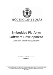
PROG for ARM® Cortex™-M processors User
PROG for ARM® Cortex™-M processors
P&E Micrcomputer Systems, Inc.
1
Purchase Agreement
P&E Microcomputer Systems, Inc. reserves the right to make changes without further notice to any products herein to
improve reliability, function, or design. P&E Microcomputer Systems, Inc. does not assume any liability arising out of the
application or use of any product or circuit described herein.
This software and accompanying documentation are protected by United States Copyright law and also by International
Treaty provisions. Any use of this software in violation of copyright law or the terms of this agreement will be prosecuted.
All the software described in this document is copyrighted by P&E Microcomputer Systems, Inc. Copyright notices have
been included in the software.
P&E Microcomputer Systems authorizes you to make archival copies of the software and documentation for the sole
purpose of back-up and protecting your investment from loss. Under no circumstances may you copy this software or
documentation for the purpose of distribution to others. Under no conditions may you remove the copyright notices from
this software or documentation.
This software may be used by one person on as many computers as that person uses, provided that the software is never
used on two computers at the same time. P&E expects that group programming projects making use of this software will
purchase a copy of the software and documentation for each user in the group. Contact P&E for volume discounts and site
licensing agreements.
P&E Microcomputer Systems does not assume any liability for the use of this software beyond the original purchase price
of the software. In no event will P&E Microcomputer Systems be liable for additional damages, including any lost profits,
lost savings or other incidental or consequential damages arising out of the use or inability to use these programs, even if
P&E Microcomputer Systems has been advised of the possibility of such damage.
By using this software, you accept the terms of this agreement. If you do not accept the terms of this agreement, do not
install the software.
©2012 P&E Microcomputer Systems, Inc.
MS-DOS & Windows are registered trademarks of Microsoft Corporation. IBM is a registered trademark of IBM corporation.
Freescale™ and the Freescale logo are trademarks of Freescale Semiconductor, Inc. ARM is a registered trademark and
Cortex is a trademark of ARM Limited. All other product or service names are the property of their respective owners.
P&E Microcomputer Systems, Inc.
98 Galen St.
Watertown, MA 02472
617-923-0053
http://www.pemicro.com
Manual version: 1.02
December 2012
PROG for ARM® Cortex™-M processors User Manual
1
2
3
OVERVIEW..................................................................................................... 1
1.1
Programming Algorithms (.ARP Files) ........................................................... 2
1.2
Start-Up Configuration.................................................................................... 2
1.3
Manual Programming ..................................................................................... 2
1.4
Scripted Programming.................................................................................... 3
1.5
Hardware Interfaces ....................................................................................... 3
1.6
Programming Utilities ..................................................................................... 3
PROGRAMMING ALGORITHMS ................................................................... 5
2.1
Algorithm File Contents .................................................................................. 5
2.2
Algorithm Timing Considerations ................................................................... 7
2.3
Modiying A Programming Algorithm............................................................... 7
2.4
Creating A Programming Algorithm................................................................ 8
PROGRAMMING COMMANDS...................................................................... 9
3.1
BM - Blank Check Module............................................................................ 10
3.2
BR - Blank Check Range ............................................................................. 10
3.3
CM - Choose Module .ARP .......................................................................... 10
3.4
EB - Erase Byte Range ................................................................................ 11
3.5
EM - Erase Module....................................................................................... 11
3.6
EW - Erase Word Range.............................................................................. 11
3.7
HE - Help...................................................................................................... 11
3.8
PB - Program Bytes...................................................................................... 11
3.9
PM - Program Module .................................................................................. 11
3.10
PW - Program Words ................................................................................... 12
3.11
QU - Quit ...................................................................................................... 12
3.12
RE - Reset chip ............................................................................................ 12
3.13
SM - Show Module ....................................................................................... 12
3.14
SS - Specify S-Record ................................................................................. 12
3.15
UM - Upload Module .................................................................................... 12
3.16
UR - Upload Range ...................................................................................... 13
3.17
VM - Verify Module....................................................................................... 13
3.18
VR - Verify Range ........................................................................................ 13
P&E Microcomputer Systems, Inc.
i
PROG for ARM® Cortex™-M processors User Manual
4
START-UP CONFIGURATION..................................................................... 15
5
CONNECTION MANAGER........................................................................... 19
6
MANUAL PROGRAMMING .......................................................................... 23
6.1
7
8
9
Manual Programming Procedure ..................................................................23
SCRIPTED PROGRAMMING (CPROG for ARM® Cortex™-M processors) 25
7.1
Startup Parameters.......................................................................................25
7.2
Configuration Commands .............................................................................28
7.3
Programming Commands .............................................................................29
7.4
Creating a .CFG File .....................................................................................30
7.5
Sample Batch File.........................................................................................32
7.6
Error Return Codes.......................................................................................32
HARDWARE INTERFACES ......................................................................... 35
8.1
USB Multilink Universal ................................................................................35
8.2
USB Multilink Universal FX ...........................................................................36
8.3
Tracelink .......................................................................................................38
8.4
Cyclone MAX ................................................................................................39
PROGRAMMING UTILITIES ........................................................................ 43
9.1
Serialize ........................................................................................................43
APPENDIX A -ALGORITHM SETUP COMMANDS .............................................. 45
APPENDIX B -ALGORITHM TABLE ENTRY ........................................................ 49
ii
P&E Microcomputer Systems, Inc.
PROG for ARM® Cortex™-M processors User Manual
1
OVERVIEW
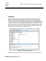
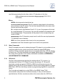
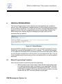
PROG for ARM® Cortex™-M processors (PROGACMP) is P&E’s programming
software for Flash/EEPROM modules that are attached to a Freescale ARM®
Cortex™-M4 processor. PROGACMP talks to the processor's background debug
module using one of P&E’s compatible hardware interfaces, such as the USB Multilink
Universal (via USB port) or Cyclone MAX (via USB, Ethernet, or Serial ports). These
interfaces connect a PC running XP/2000/2003/Vista/7 to a debug connector on the
target system. This connector provides access to the debug signals of the processor
chip mounted on your target system hardware board.
Figure 1-1: PROG User Interface
As part of the programming procedure, the user will need to select a programming
P&E Microcomputer Systems, Inc.
1
PROG for ARM® Cortex™-M processors User Manual
algorithm that will enable the PROG for ARM Cortex-M processors software to
properly manage their specific target device during programming. The user may also
choose to set certain programming parameters before beginning to program. This
chapter presents a brief overview of the programming procedure.
1.1
Programming Algorithms (.ARP Files)
PROG for ARM Cortex-M processors runs on the PC and provides a set of general
interface functions and processor-specific user functions that are used to control the
erasing, verifying, programming and viewing of modules to be programmed. These
general functions are implemented for a particular target configuration and chip set by
using specific Programming Algorithm ( .ARP) files that the user can modify to reflect
the setup of their particular target interface. PROG for ARM Cortex-M processors
includes a library of these programing algorithms. For the most recent version of this
library of algorithms, please visit our website, www.pemicro.com.
Programming algorithm files can also be modified by the user according to specific
conventions. In addition, P&E can create programming algorithms upon request if you
are working with a device whose corresponding algorithm is not included in the current
library. Detailed information about programming algorithms, including their contents
and instructions for modification, is included in CHAPTER 2 – PROGRAMMING
ALGORITHMS.
1.2
Start-Up Configuration
Certain programming parameters can be adjusted when launching the PROG for ARM
Cortex-M processors software by using the executable command-line to input the
appropriate parameters. These include settings related to target speed, delay cycles,
and S-record verificaton, among others. A list of specific parameters with examples of
their usage is included in CHAPTER 4 – START-UP CONFIGURATION.
1.3
Manual Programming
PROG for ARM Cortex-M processors lists commands that are available to execute.
Any of the programmer’s enabled features can be selected by using the mouse, the
up and down arrow keys, or by typing the selection letters to the left of the selection
display. Pressing ENTER or double clicking the mouse will execute the highlighted
entry if it is enabled. The user will be prompted for any additional information that is
required to execute the selected function. Before you can program a module from an
S record file, you must select such a file. If you try to do a program module function
and you have not selected an S-record file, you will be asked to select one. A list of
2
P&E Microcomputer Systems, Inc.
PROG for ARM® Cortex™-M processors User Manual
programming commands and their functions may be found in CHAPTER 6 –
MANUAL PROGRAMMING.
1.4
Scripted Programming
Programming commands, in addition to be executed manually, may also be collected
into script files which can be used to automate the programming process. These
scripts are executed by a command-line programming application called CPROG for
ARM Cortex-M processors, which is included with the PROG for ARM Cortex-M
processors software. More information about scripted programming is located in
CHAPTER 7 – SCRIPTED PROGRAMMING (CPROG for ARM® Cortex™-M
processors).
1.5
Hardware Interfaces
In addition to PROG for ARM Cortex-M processors programming procedures, this
manual discusses hardware interfaces that may be used in conjuction with the PROG
for ARM Cortex-M processors. For supported Freescale processors, P&E typically
offers both value-oriented development solutions and more robust and versatile
production solutions. You can learn about these interfaces in CHAPTER 8 –
HARDWARE INTERFACES.
1.6
Programming Utilities
P&E also offers some no-cost programming utilities to help the user perform certain
tasks. More information is available in CHAPTER 9 – PROGRAMMING UTILITIES.
P&E Microcomputer Systems, Inc.
3
PROG for ARM® Cortex™-M processors User Manual
2
PROGRAMMING ALGORITHMS
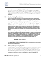
P&E’s .ARP programming algortihm files define the functions necessary for PROG for
ARM Cortex-M processors to program a Freescale ARM® Cortex™-M4 family
processor’s internal flash or connected external Flash/EEPROM. After you choose the
appropriate algorithm, it will appear in the Configuration Window.
Figure 2-1: Configuration Window
2.1
Algorithm File Contents
You may view and, if necessary, modify the contents of an algorithm by opening it in
any text editor. A .ARP programing algorithm file consists of four parts:
1. Comments
2. User-specified functions
3. Setup commands
4. S-records
2.1.1
Comments
Comments are usually placed in the file to identify the target system for which the
.ARP file was written and what module on the target system it programs, as well as
other useful information. If a specific .ARP file is selected in PROG for ARM Cortex-M
processors, these comments are shown in the window at the bottom of the PC screen.
Within the algorithm file, a semicolon is used to designate the beginning of a
comment.
2.1.2
User Specified Functions
There can be up to six user-specified functions included in a .ARP file. Each user
statement in the .ARP file must have a corresponding address in same order as the
table part of the S-records and an appropriate set of code. A line which defines a user
P&E Microcomputer Systems, Inc.
5
PROG for ARM® Cortex™-M processors User Manual
specified programming function has a total of 57 characters in the form:
USER=uuuuuuuuuuuuuuuuuuuuuuNpppppppppp/llllllll/
uuuuuuuu/
Where:
USER= is the keyword to identify the line
uuuuuuuuuuuuuuuuuuuuuu is the 22 character string placed in the selection
menu window on the PC screen. The first few characters define the menu select
function and should be unique.
N is a single numeric digit between 0 and 4. If it is zero, the program will not ask
for a user parameter. If it is non-zero, the user will be asked for a parameter with
N hexadecimal digits. This parameter will be passed to the corresponding user
routine in RAM.
pppppppppp is the 10 character prompt used to solicit the user input parameter.
/ is required for error checking.
llllllll is an 8 hex character lower bound on the user parameter.
uuuuuuuu is an 8 hex character upper bound on the user parameter.
2.1.3
Setup Commands
Setup Commands are used to initialize the target CPU when it is not possible to do so
using the enable function, which must first be loaded into target RAM before
execution. Setup commands appear alone on a separate line of the .ARP file starting
in column one. All setup commands must appear before the first S record in the .ARP
file or they will be ignored. A list of setup commands is available in APPENDIX A ALGORITHM SETUP COMMANDS.
2.1.4
S-Records
Any line in the programming algorithm file starting with an "S" in column 1 is
considered an S-record. S1, S2 and S3 records are allowed. S7, S8 and S9
termination records are ignored. PROG for ARM Cortex-M processors uses the
address field on the first S record detected in the file as the starting address of target
RAM. Each .ARP file in the library contains a programming algorithm for a particular
device.
The S records are loaded into on chip RAM on the ARM® Cortex™-M4
microcontroller and provide the functions necessary to carry out the functions
specified below. All other records are written to the screen when the .ARP file is
6
P&E Microcomputer Systems, Inc.
PROG for ARM® Cortex™-M processors User Manual
selected for programming. PROG for ARM Cortex-M processors programming
algorithm files must have the DOS filename extension ".ARP" in order for PROG for
ARM Cortex-M processors to find them. The files are in ASCII and are thus readable
using most text editors. The S records for a .ARP file can be generated using most
assemblers.
2.2
Algorithm Timing Considerations
Most current flash devices have an on-chip programming monitor. The processor
passes a command to the flash device, such as Program Word, and the flash device
executes this command. On all Freescale processors with On-Chip flash, and on
some external flash devices, the timing is provided by the processor. In order to
program the flash device according to specification, the programming software on the
PC has to know how fast the target processor is running. By default, the PROG for
ARM Cortex-M processors software tries to determine automatically how fast the
target is running by loading a delay routine in the processor and timing how long it
takes to execute. Under a multitasking environment, such as XP/2000/2003/Vista/7,
although they are usually very accurate, these timing measurements are not always
correct.
P&E addresses this by providing a command-line mechanism that allows the user to
inform the PROG software how fast the target processor is running. The ensures that
the timing in the algorithms is always correct. To do this, the user would include the
FREQ indentifier on the executable command-line, followed by the INTERNAL clock
frequency in Hertz. For instance, if your processor is a MK40X256 with a bus
frequency of 20MHz, your command-line parameters should look like this:
PROGACMP freq 20000000
See CHAPTER 4 – START-UP CONFIGURATION for more information about how to
use command-line parameters.
2.3
Modiying A Programming Algorithm
In certain situations, users may wish to modify a programming algorithm file in order to
perform functions like turning off a watchdog, enabling port pins, speeding up the
algorithm, etc. This can typically be accomplished by opening the algorithm in a text
editor and modifying the Setup Commands. For a list of Setup Commands and their
corresponding parameters, please see APPENDIX A - ALGORITHM SETUP
P&E Microcomputer Systems, Inc.
7
PROG for ARM® Cortex™-M processors User Manual
COMMANDS.
2.4
Creating A Programming Algorithm
In certain situations, a user may wish to either create their own programming
algorithm or make significant modifications to an existing file.
A .ARP file is a structured file which contains a table of essential system constants
and routine addresses. This table is followed by the definitions of the routines.
Register and memory usage conventions must be followed when your insert your own
set of routines. Any routine which can not or need not be provided is given a zero (0)
address in the table. The table, routines, stack and buffer reside in the CPU on chip
RAM during the execution of PROG for ARM Cortex-M processors. Routines return to
PROG for ARM Cortex-M processors by executing a breakpoint (BKPT) instruction.
The table contains several long word (32-bit) entries listed in an exactly specified
order. A listing of the table entries and their order may be found in APPENDIX B ALGORITHM TABLE ENTRY. In addition, the table is assembled at the starting
address at which the on chip RAM will be configured during execution of PROG for
ARM Cortex-M processors. Furthermore, the table must be the first thing assembled
to insure that it is the first S record in the .ARP file.
Examples of the assembler files (.ASM files) used to produce the .ARP files for
external flash are available upon request. The first part of each file is the table that
generates S records. The origin or the table tells the PC program where the on chip
RAM should be configured during the programming process. The choice is made in a
manner that does not conflict with other things in the target system, such as the
module to be programmed.
The programming routines for a particular module are loaded into the ARM®
Cortex™-M4 processor’s on-chip RAM for execution during erasure, programming,
verification and showing of the module. The routines and associated comments for a
particular module are in the form of Freescale S-records stored in the .ARP
programming algorithm.
8
P&E Microcomputer Systems, Inc.
PROG for ARM® Cortex™-M processors User Manual
3
PROGRAMMING COMMANDS
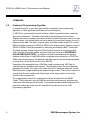
When the user performs manual programming, commands are executed by selecting
them from the Choose Programming Function Window pick list. The user may either
use the up/down arrow keys or type the two-letter abbreviation for the command
(listed below) on the command line to select a command. Pressing ENTER causes
the selected command to execute. Commands can also be executed from the Menus
or from the Button Bar. If there is any additional information needed in order to
execute the command, the user will be prompted for this information in a new window.
Errors caused by a command or any other responses will be presented in the Status
Window.
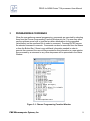
Figure 3-1: Choose Programming Fucntion Window
P&E Microcomputer Systems, Inc.
9
PROG for ARM® Cortex™-M processors User Manual
At any given time, or for a particular module, some of the commands may not be
active. Inactive commands are indicated as such in the Choose Programming
Functions Window and will not execute.
Below is a description of each of the PROG for ARM Cortex-M processors commands
used in manual programming. These same commands are also used in scripted
programming. For more information about scripted programming, see CHAPTER 7 –
SCRIPTED PROGRAMMING (CPROG for ARM® Cortex™-M processors).
3.1
BM - Blank Check Module
This command checks the entire module to see if it has been erased. If not, the
address of the first non-blank location is given along with its contents.
3.2
BR - Blank Check Range
This command checks to see if a specified range of locations has been erased. The
user is prompted for the starting and ending addresses. These addresses must lie
within the addressing range of the module or an error will be returned. If the range is
not erased, the first non-blank location is given along with its contents.
3.3
CM - Choose Module .ARP
The user is presented with a list of available .ARP files. Each .ARP file contains
information on how to program a particular module. Usually, the name of the file
indicates what kind of module it relates to. For example, the file
Freescale_MK40X256_1x32x64k_PFlash.ARP specifies how to program the 256K
PFlash block on a MK40X256 processor. Setup information and further descriptions of
the module are provided in ASCII text within the module file. This information is
presented in the status window when a .ARP file is selected. The user can also look at
this information inside of the module itself by using any standard text editor to view the
module contents.
A particular .ARP file is selected by using the arrow keys to highlight the file name and
then pressing ENTER. The currently selected .ARP file is shown in the .ARP file
selected window. After a .ARP file is selected, the user is prompted for the base
address of the module. This address is used as the beginning address for the module
during programming and verification. Certain .ARP files, such as those for external
flash flash algorithms, will prompt the user for the base address of the module.
10
P&E Microcomputer Systems, Inc.
PROG for ARM® Cortex™-M processors User Manual
3.4
EB - Erase Byte Range
This command erases bytes in a specified range of locations. The user is prompted
for the starting and ending addresses. These addresses must lie within the addressing
range of the module or an error will be returned. If the range is not erased, the first
non-blank location is given along with its contents.
3.5
EM - Erase Module
This command erases the entire module. If the entire Module is not erased, an error
message will be returned.
3.6
EW - Erase Word Range
This command erases words in a specified range of locations. The user is prompted
for the starting and ending addresses. These addresses must lie within the addressing
range of the module or an error will be returned. If the range is not erased, the first
non-blank location is given along with its contents.
3.7
HE - Help
Opens this PROG for ARM Cortex-M processors user manual.
3.8
PB - Program Bytes
The user is prompted for a starting address, which must be in the module. The user is
then shown an address and a byte. Pressing ENTER shows the next location. The
user can also enter in hex a byte to be programmed into the current location. In
addition, the symbols +, -, or = may be appended to the value being written. They
correspond respectively to increase the address (default), decrease the address, and
hold the address constant. Failure to program a location, entering an invalid hex value
or exceeding the address range of the module will exit the program bytes window. If a
location fails to program, an error message will be returned.
3.9
PM - Program Module
For this command to work, the user must have previously selected an S-record file.
The S-records are then checked to see if they all reside in the module to be
programmed. If not, the user is asked if they want to continue. If the answer is yes,
only those S-record addresses which lie in the module are programmed. If a location
cannot be programmed, an error message will be returned.
P&E Microcomputer Systems, Inc.
11
PROG for ARM® Cortex™-M processors User Manual
3.10
PW - Program Words
The user is prompted for a starting address, which must be in the module. The user is
then shown an address and a word. Pressing ENTER shows the next location. The
user can also enter in hex a word to be programmed into the current location. In
addition, the symbols +, -, or = may be appended to the value being written. They
correspond respectively to: increase the address (default), decrease the address, and
hold the address constant. Failure to program a location, entering an invalid hex value
or exceeding the address range of the module will exit the program words window. If
a location fails to program, an error message will be returned.
3.11
QU - Quit
Terminates PROG for ARM Cortex-M processors and returns to Windows.
3.12
RE - Reset chip
This causes a hardware reset to the ARM® Cortex™-M4 microcontroller. This
command can be used to recover from errors which cause the programmer not to be
able to talk to the processor through the background debug mode.
3.13
SM - Show Module
The user is prompted for a starting address. If this address is not in the module and
error is given. A window is opened which shows the contents of memory as hex bytes
and ASCII characters if printable. Non-printing characters are shown as periods (".").
This window stays on the screen until the user presses ESCAPE.
3.14
SS - Specify S-Record
Asks the user for the name (and/or path) to a file of S-records to be used in
programming or verifying a module. If the file is not found, an error message is given.
The currently selected file is shown in the S19 file selected window. The programmer
accepts S1, S2, and S3 records. All other file records are treated as comments. If the
user does not specify a file name extension, a default of .S19 is used.
3.15
UM - Upload Module
The user is asked for a filename into which to upload S-records. The default filename
extension is set to .S19 if none is specified by the user. S-records for the entire
module are then written to the specified file.
12
P&E Microcomputer Systems, Inc.
PROG for ARM® Cortex™-M processors User Manual
3.16
UR - Upload Range
The user is prompted for a starting address, which must be in the module. Next, the
user is asked for an ending address, which must also be in the module. The user is
then asked for a filename into which to upload S-records. The default filename
extension is set to .S19 if none is specified by the user. S-records are then written to
the specified file.
3.17
VM - Verify Module
For this command to work, the user must have previously selected an S-record file.
The S-records are then checked to see if they all reside in the module to be
programmed. If not, the user is asked if they want to continue. If the answer is yes,
only those S-record addresses which lie in the module are verified. If a location cannot
be verified, an error message will be returned which indicates the address, the
contents of that address, and the contents specified in the S-record file.
3.18
VR - Verify Range
For this command to work, the user must have previously selected an S-record file.
The user is prompted for a starting address, which must be in the module. Next, the
user is asked for an ending address, which must also be in the module. S-record
addresses which lie in the module are verified. If a location cannot be verified, an
error message will be returned which indicates the address, the contents of that
address, and the contents specified in the S-record file.
In addition, there is one function that is allowed to be unique to the module being
programmed. The selection menu name and the length of up to one hexadecimal
parameter may be specified in a supporting .ARP file.
P&E Microcomputer Systems, Inc.
13
PROG for ARM® Cortex™-M processors User Manual
4
START-UP CONFIGURATION
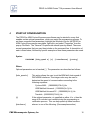
The PROG for ARM Cortex-M processors software may be started in a way that
enables certain optional parameters, which can assist the programming process. To
set these command-line parameters, highlight the Windows Icon for the PROG for
ARM Cortex-M processors executable, right-click, and select “Properties” from the
pop-up File Menu. The “General” Properties tab should open by default. There are
several parameters that you may then include on the command line. A description of
each is listed below, followed by specific examples of how these parameters are used.
Syntax:
PROGACMP [bdm_speed n] [v] [interface=x] [port=y]
Where:
Optional parameters are in brackets [ ]. The parameters are described as follows:
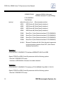
[bdm_speed n]
This option allows the user to set the BDM shift clock speed of
P&E's BDM interfaces. This integer value may be used to
determine the speed of communications according to the
following equations:
Cyclone MAX : (50000000/(2*N+5)) Hz
USB Multilink Universal : ( 1000000/(N+1)) Hz
USB Multilink Universal FX : ( 25000000/(N+1)) Hz
Tracelink : (50000000/(2*N+5)) Hz
[v]
If the optional parameter v is specified as either V or v, then the
range of S-records is not verified during the programming or
verification process. This can help speed up these functions.
[interface=x]
where x is one of the following: (See examples section)
P&E Microcomputer Systems, Inc.
15
PROG for ARM® Cortex™-M processors User Manual
USBMULTILINK
(supports Multilink Universal,
Multilink Universal FX, and OSJtag)
CYCLONEMAX
TRACELINK
[port=y]
where the value of y is:
(See examples section)
USB1
USB Device #1 (Must Specify Interface)
USB2
USB Device #2 (Must Specify Interface)
USB3
USB Device #3 (Must Specify Interface)
USB4
USB Device #4 (Must Specify Interface)
COM1
Serial Port 1 (Auto Selects Interface=CYCLONEMAX)
COM2
Serial Port 2 (Auto Selects Interface=CYCLONEMAX)
COM3
Serial Port 3 (Auto Selects Interface=CYCLONEMAX)
COM4
Serial Port 4 (Auto Selects Interface=CYCLONEMAX)
#.#.#.#
Ethernet IP address #.#.#.#. Each # symbol represents
a decimal number between 0 and 255. (Auto Selects
Interface=CyclonePro)
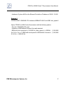
Example 1
CPROGACMP C:\ENGINE.CFG Interface=USBMULTILINK Port=USB1
Opens CPROG for ARM Cortex-M processors with the following options:
- Run the C:\ENGINE.CFG script
- Interface is USB Multilink Universal, first cable detected.
Example 2
CPROGACMP C:\ENGINE.CFG Interface=CYCLONEMAX Port=209.61.110.251
Opens CPROG for ARM Cortex-M processors with the following options:
- Run the C:\ENGINE.CFG script
16
P&E Microcomputer Systems, Inc.
PROG for ARM® Cortex™-M processors User Manual
- Interface is Cyclone MAX via the Ethernet Port with an IP address of 209.61.110.251
Example 3
CPROGACMP C:\ENGINE.CFG Interface=USBMULTILINK Port=USB1 bdm_speed 0
Opens CPROG for ARM Cortex-M processors with the following options:
- Run the C:\ENGINE.CFG script
- Interface is USB Multilink Universal, first cable detected.
- BDM shift clock speed set to 1,000,000 Hz. [bdm_speed n] = USB-ML : ( 1,000,000/
(N+1)) Hz. For n = 0, BDM shift clock speed for USB Multilink Universal = ( 1,000,000/
(0+1)) Hz = 1,000,000 Hz
P&E Microcomputer Systems, Inc.
17
PROG for ARM® Cortex™-M processors User Manual
5
CONNECTION MANAGER
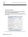
Before programming your device, you will need to connect to your target using a
hadware interface. Interface options for PROG for ARM Cortex-M processors are
discussed in Section 8 - HARDWARE INTERFACES.
Once you have physically connected your PC to your target using the hardware
interface, and the appropriate drivers are installed, the following Connection Manager
dialog will appear:
Figure 5-1: Connection Manager Dialog
The Connection Manger allows you to choose the interface that you wish to use and
P&E Microcomputer Systems, Inc.
19
PROG for ARM® Cortex™-M processors User Manual
configure the connection.
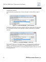
Use the Interface drop-down menu to choose the type of interface that you plan to
use.
Figure 5-2: Connection Manager - Select Interface
Then select the interface from those available, which are listed in the Port drop-down
list. The Refresh List button to the right may be used to update the list of available
interfaces.
Figure 5-3: Connection Manager - Select Port
The Add LPT Port button to the right allows you to manually specify a parallel port
address. This allows you to use virtual or PCI-based parallel ports which are not
specified in the computer’s BIOS. The following dialog will appear, which you can use
to configure the port:
20
P&E Microcomputer Systems, Inc.
PROG for ARM® Cortex™-M processors User Manual
Figure 5-4: Connection Manager - Add LPT Port
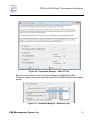
Back in the main window of the Connection Manager, the BDM Debug Shift
Frequency can be selected from the drop-down list in the BDM Communication Speed
section.
Figure 5-5: Connection Manager - BDM Shift Freq.
P&E Microcomputer Systems, Inc.
21
PROG for ARM® Cortex™-M processors User Manual
You may also choose to auto-detect or manually specifcy the MCU bus frequency in
the MCU Internal Bus Frequency section.
Below that, you have the option of setting a reset delay.
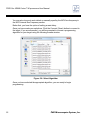
Once you have made your selections, Click the Connect (Reset) button to connect to
the target. If you are successful, you will be prompted to choose a programming
algorithm for your target using the following browse window:
Figure 5-6: Select Algorithm
Once you have selected the appropriate algorithm, you are ready to begin
programming.
22
P&E Microcomputer Systems, Inc.
PROG for ARM® Cortex™-M processors User Manual
6
MANUAL PROGRAMMING
The Choose Programming Function Window lists commands that are available to
execute. Any of the programmer’s enabled features can be selected using the mouse,
the up and down arrow keys, or by typing the two-letter command abbreviations that
appear to the left of the list of programming functions into the Status Window. The
Status Window also displays any error messages that might result from the
commands that you perform.
Figure 6-1: Status Window
Pressing ENTER or double clicking the mouse in the Choose Programming Function
Window will execute the highlighted entry if it is enabled. The user will be prompted
for any additional information that is required to execute the selected function. Before
you can program a module from an S record file, you must select such a file. If you try
to do a program module function and you have not selected a file, you will be asked to
select one.
6.1
Manual Programming Procedure
Here is the procedure for performing manual programming:
1. Before turning on your power supply, check that the target power supply
is on and the interface cable is connected to your target board. Be sure
to apply proper target voltage before programming the flash. If you lose
contact with your target board at any time during the procedure, you may
double-click the "RE" command (Reset) to begin again.
P&E Microcomputer Systems, Inc.
23
PROG for ARM® Cortex™-M processors User Manual
2. Using the PROG for ARM Cortex-M processors software, choose the programming algorithm by selecting the appropriate .ARP file. Double clicking the "CM" (Choose Module) command will allow you to select the
algorithm you wish to use.
3. After you select the .ARP file, you may be asked for the base address.
This is the address at which you would like to program the code. Enter
the appropriate base address.
4. a) Use the "EM" (Erase Module) command to erase the module at that
location. The process of erasing the module will vary according to the
size of the flash, but should take no longer than 30 seconds. If this procedure seems to be taking much longer than 30 seconds, then the computer
is probably not getting a proper response from the board. If this is the
case:
b) Check the jumper setting on your target board, as well as the
programming voltage.
5. Some programming algorithms have a special command, such as "BE,"
for block erase. If you are unable to double-click the "EM" (Erase Module)
command, try using the "BE" (Block Erase) command. Some commands
are hidden and you may need to use the scroll bar to scroll down to these
commands.
6. You may check to see whether or not the module has been erased by
double-clicking the "BM" command (Blank Check Module). If the flash is
not properly erased then this command will give you an error message.
You may also check the contents of the memory locations by double-clicking the "SM" (Show Module) command. If the flash has been erased
properly then all the memory locations will display "FF".
7. Now use the "SS" command (Specify S Record) to load the object file
(.S19), which you should have generated previously by using a compiler
or an assembler. This command will ask for the name of the .S19 file.
8. Now you ready to program the flash. Double click the "PM" command
(Program Module) to begin the programming process.
9. In order to check the results, use the "SM" command (Show Module) with
the appropriate base address to view the contents of the flash. You
should see that the flash has been correctly programmed. You may also
double-click the “VM” command (Verify Module) to verify that all the bytes
of the flash are correctly programmed.
24
P&E Microcomputer Systems, Inc.
PROG for ARM® Cortex™-M processors User Manual
7
SCRIPTED PROGRAMMING (CPROG for ARM® Cortex™-M
processors)
Programming commands, in addition to be executed manually, may also be collected
into script files which can be used to automate the programming process. These
scripts are executed by a command-line programming application called CPROG for
ARM Cortex-M processors, which is included with the PROG for ARM Cortex-M
processors software. Both the USB Multilink Universal as well as the Cyclone MAX
are recommended hardware interfaces for connecting to the target processor. When
you run the CPROGACMP.EXE application, it will look for the PROG.CFG script file
and automatically execute the commands in that file.
7.1
Startup Parameters
The CPROG for ARM Cortex-M processors software may be started in a way that
enables certain optional parameters, which can assist the programming process. To
set these command-line parameters, highlight the Windows Icon for the CPROG for
ARM Cortex-M processors executable, right-click, and select “Properties” from the
pop-up File Menu. The “General” Properties tab should open by default. There are
several parameters that you may then include on the command line. A description of
each is listed below. To see some of these parameters used in an example, please
see Section 7.4.1 - Example .CFG File.
Syntax:
CPROGACMP [?] [filename] [v] [reset_delay n] [bdm_speed n]
[hideapp] [freq n] [Interface=x] [port=y]
[showports] [/logfile logfilename]
Where:
The parameters are described as follows:
[filename]
a file containing programming commands and comments,
P&E Microcomputer Systems, Inc.
25
PROG for ARM® Cortex™-M processors User Manual
default = PROG.CFG.
[Interface=x]
where x is one of the following:
USBMULTILINK
(supports Multilink Universal,
Multilink Universal FX, and OSJtag)
CYCLONEMAX
TRACELINK
[Port=y]
Where the value of y is:
USB1
- USB Device #1 (Must Specify Interface)
USB2
- USB Device #2 (Must Specify Interface)
USB3
- USB Device #3 (Must Specify Interface)
USB4
- USB Device #4 (Must Specify Interface)
COM1
- Serial Port 1 (Auto Selects
Interface=CycloneMax)
COM2
- Serial Port 2 (Auto Selects
Interface=CycloneMax)
COM3
- Serial Port 3 (Auto Selects
Interface=CycloneMax)
COM4
- Serial Port 4 (Auto Selects
Interface=CycloneMax)
#.#.#.#
26
Ethernet IP address #.#.#.#. Each # symbol
represents a decimal number between 0 and
255. Must specify interface. (Auto Selects
Interface=CycloneMax)
[v]
Causes the programmer not to check the range of S record
addresses before programming or verifying. This speeds up
the programming process. The option should be used with
care as all out of range s-records will be ignored.
[reset_delay n]
Specifies a delay after the programmer resets the target that
we check to see if the part has properly gone into background
debug mode. This is useful if the target has a reset driver
which hold the MCU in reset after the programmer releases
the reset line. The n value is a delay in milliseconds.
[bdm_speed n]
This option allows the user to set the BDM shift clock speed
of P&E's debug interface. This integer value may be used to
P&E Microcomputer Systems, Inc.
PROG for ARM® Cortex™-M processors User Manual
determine the speed of communications according to the
following equations:
Cyclone Max/Tracelink : (50000000/(2*N+5)) Hz
USBMultilink : (1000000/(N+1)) Hz
USBMultilinkFX: (25000000/(N+1)) Hz
OSJTAG: 250000 Hz
The value n should be between 0 and 31. This shift clock
takes effect after the commands in the top of the
programming algorithm are executed so that these
commands can increase the target frequency and allow a
faster shift clock. This clock can't generally excede a div 4 of
the processor bus frequency.
[?]
Use the '?' character option to cause the commandline
programmer to wait and display the result of programming in
the PROG window. If the user does not use a batch file to test
errorlevel, this provides a method to display the programming
result. This option should be the FIRST commandline option.
[hideapp]
This will cause the commandline programmer to not display a
visual presence while running with the exception of appearing
on the taskbar. 32-bit applications only!
[freq n]
By default, the PROG for ARM Cortex-M processors software
tries to determine automatically how fast the target is running
by loading a delay routine in the processor and timing how
long it takes to execute. On some machines, this may yield
inconsistent results which may affect algorithms which
program flash internal to an MCU. P&E provides a commandline mechanism allowing the user to inform the PROG
software exactly how fast the target processor is running. In
this way, the timing in the algorithms will be precise. On the
command-line, you specify the INTERNAL clock frequency in
Hertz following the 'FREQ' identifier. Note that in general if
you are using a flash device external to the MCU, this timing
parameter is not needed as the flash handles the timing itself.
[showports]
The command-line programmer outputs all available ports to
a text file and then terminates (regardless of other commandline parameters). This information output to the text file
P&E Microcomputer Systems, Inc.
27
PROG for ARM® Cortex™-M processors User Manual
includes the parameters needed to contact this piece of
hardware as well as a description of the hardware interface.
The default output filename is ports.txt and is created in the
same folder as CPROG for ARM Cortex-M processors. The
output can also be directed to a different file.
Example:
SHOWPORTS=C:\MYPORTS.TXT .
[/logfile logfilename]
This option opens a logfile of the name "logfilename" which
will cause any information which is written to the status
window to also be written to this file. The "logfilename" should
be a full path name such as c:\mydir\mysubdir\mylog.log.
Example:
C:\PROJECT\CPROG for ARM Cortex-M processors
INTERFACE=CYCLONEMAX PORT=USB1
BDM_SPEED 1 C:\PROJECT\ENGINE.CFG
Opens CPROG for ARM Cortex-M processors with
the following options:
Select PCI Lightning Card 1
Set BDM_SPEED = 1 which has a BDM shift clock of
4.714MHZ
Run the C:\ENGINE.CFG script
7.2
Configuration Commands
Configuration commands all start with a colon followed by the command name. Lines
starting with characters which are not configuration or programming commands are
listed as remarks.
:providepower n
Determines whether interface should provide power to the target.
Valid values of n are:
0 : Interface does not provide power to target. (default)
1 : Enable Interface provides power to target.
(note: command is the same as legacy option :[useprorelays] n)
:powerdowndelay n Amount of time to delay when the power to the target is turned off
for the targets power supply to drop to below 0.1v. n is the time in
milliseconds.
28
P&E Microcomputer Systems, Inc.
PROG for ARM® Cortex™-M processors User Manual
:powerupdelay n
Amount of time to delay when the power to the target is turned on
OR the target is reset, and before the software attempts to talk to
the target. This time can be a combination of power on time and
reset time (especially if a reset driver is used).
n is the time in milliseconds.
:poweroffonexit n
Determines whether power provided to the target should be
turned off when the CPROGACMP application terminates.
Valid values of n are:
0 : Turn power off upon exit (default)
1 : Keep power on upon exit
:useswd n
Determines whether interface should use SWD reduced pin
protocol for communications if the interface supports it. Valid
values of n are:
0 : Interface does not use SWD, instead connects with JTAG.
(default)
1 : Interface uses SWD to connect if possible.
If n is omitted : Interface uses SWD.
7.3
Programming Commands
Programming commands all start with a two character sequence followed by white
space (blanks or tabs). Lines starting with characters which are not programming or
configuration commands are listed as remarks. The term “filename” means a full path
to a file. Programming commands use the same two letter codes as used in the
interactive programmer PROG for ARM Cortex-M processors. The same .ARP files
used by PROG for ARM Cortex-M processors are used to set up for a particular
device to be programmed. If a user function is specified for a particular device, its two
character command and the meaning or user_par are specified in the .ARP file.
Detailed descriptions of commands that CPROG for ARM Cortex-M processors and
PROG for ARM Cortex-M processors have in common may be found in CHAPTER 3
– PROGRAMMING COMMANDS.
BM
Blank check module.
BR starting ending
Blank check range.
EB starting ending
Erase byte range.
P&E Microcomputer Systems, Inc.
29
PROG for ARM® Cortex™-M processors User Manual
7.4
EW starting ending
Erase word range.
EM
Erase module.
PB starting byte ... byte
Program bytes.
PW starting word ... word
Program words.
PM
Program module.
CM filename base_address
Choose module .ARP file.
VM
Verify module.
VR starting ending
Verify range.
UM filename
Upload module.
UR starting ending filename
Upload range.
SS filename
Specify S record.
SM starting ending
Show module.
HE
Help (look at cprog.doc file).
QU
Quit.
RE
Reset chip.
GO
Start Device Running (optionally use as last
command if you want the device to run for
testing. Should be immediately preceded
with an 'RE' command).
DE timeinms
Delays "timeinms" milliseconds
Creating a .CFG File
To perform scripted programming, the user should create a .CFG file which lists
commands for CPROG to follow in sequence. You may use any text editor to create a
file with the commands you wish to include. You should then save your file as
PROG.CFG, because this is the filename that the CPROG software looks for by
default.
7.4.1
Example .CFG File
Example .CFG file:
30
Result of Commands (Results are not included in
.CFG file):
P&E Microcomputer Systems, Inc.
PROG for ARM® Cortex™-M processors User Manual
RE
Resets the target board.
CM Freescale_MK40X256_1x32x64k_PFlash.ARP
Chooses a Flash module on K40X256 and sets the
base address.
SS file_1.s19
Loads the S19 file into PC memory.
PM
Programs the Flash.
VM
Reads the Flash and compares it with the .S19 file
in the PC memory to verify that it downloaded
properly.
CM Freescale_MK40X256_1x32x64k_PFlash.ARP
Chooses the PFlashmodule on K40X256 and sets
the base address.
SS file2.s19
Loads the S19 file into PC memory.
PM
Programs the Flash.
VM
Reads the Flash and compares it with the .S19 file
in the PC memory to verify that it downloaded
properly.
Note:
7.4.2
You must use full pathnames to all files (do not use relative paths).
Changing The .CFG Filename
If you want to use a .CFG file that is named something other than PROG.CFG, you
must specify the name of the .CFG file on the command line when you run CPROG for
ARM Cortex-M processors. To add this parameter to the command line, right-click on
the Windows Icon for the CPROG executable, and select Properties. The “General”
Properties tab should be selected by default. Add the appropriate parameter to the
command-line here. For example, to use EE_PROG.CFG as your script file, type the
following (assuming your executable has been installed in the default path):
c:\pemicro\progw\CPROGACMP.EXE EE_PROG.CFG
P&E Microcomputer Systems, Inc.
31
PROG for ARM® Cortex™-M processors User Manual
7.5
Sample Batch File
Here is an example of calling the commandline programmer and testing its error
code return in a simple batch file. A sample batch file is shown here:
C:\PROJECT\CPROGACMP interface=USBMULTILINK port=USB1
BDM_SPEED 0 C:\PROJECT\ENGINE.CFG
if errorlevel 1 goto bad
goto good
:bad
ECHO BAD BAD BAD BAD BAD BAD BAD BAD
:good
ECHO done
7.6
Error Return Codes
Error returns are provided so they may be tested in .BAT files. The
error codes used are:
0 - Program completed with no errors.
1 - Cancelled by user.
2 - Error reading S record file.
3 - Verify error.
4 - Verify cancelled by user.
5 - S record file is not selected.
6 - Starting address is not in module.
7 - Ending address is not in module or is less than starting address.
8 - Unable to open file for uploading.
9 - File write error during upload.
10 - Upload cancelled by user.
11 - Error opening .ARP file.
12 - Error reading .ARP file.
32
P&E Microcomputer Systems, Inc.
PROG for ARM® Cortex™-M processors User Manual
13 - Device did not initialize.
14 - Error loading .ARP file.
15 - Error enabling module just selected.
16 - Specified S record file not found.
17 - Insufficint buffer space specified by .ARP to hold a file S record.
18 - Error during programming.
19 - Start address does not point into module.
20 - Error during last byte programming.
21 - Programming address no longer in module.
22 - Start address is not on an aligned word boundary.
23 - Error during last word programming.
24 - Module could not be erased.
25 - Module word not erased.
26 - Selected .ARP file does not implement byte checking.
27 - Module byte not erased.
28 - Word erase starting address must be even.
29 - Word erase ending address must be even.
30 - User parameter is not in the range.
31 - Error during .ARP specified function.
32 - Specified port is not available or error opening port.
33 - Command is inactive for this .ARP file.
34 - Cannot enter background mode. Check connnections.
35 - Not able to access processor. Try a software reset.
36 - Invalid .ARP file.
37 - Not able to access processor RAM. Try a software reset.
38 - Initialization cancelled by user.
39 - Error converting hexadecimal command number.
40 - Configuration file not specified and file prog.cfg does not exist.
41 - .ARP file does not exist.
42 - Error in io_delay number on command line.
P&E Microcomputer Systems, Inc.
33
PROG for ARM® Cortex™-M processors User Manual
43 - Invalid command line parameter.
44 - Error specifying decimal delay in milliseconds.
47 - Error in script file.
49 - Cable not detected
50 - S-Record file does not contain valid data.
51 - Checksum Verification failure - S-record data does not match MCU memory.
52 - Sorting must be enabled to verify flash checksum.
53 - S-Records not all in range of module. (see "v" commandline parameter)
54 - Error detected in settings on commandline for port/interface
60 - Error calculating device CRC value
61 - Error - Device CRC does not match value given
70 - Error - CPROG is already running
34
P&E Microcomputer Systems, Inc.
PROG for ARM® Cortex™-M processors User Manual
8
HARDWARE INTERFACES
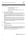
P&E’s USB Multilink Universal, USB Multilink Universal FX, and Cyclone MAX offer
three effective hardware interfaces for use with PROG for ARM Cortex-M processors.
The USB Multilink Universal and USB Multilink Universal FX are development tools
that communicate via USB and will enable you to debug your code and program it
onto your target. The Cyclone MAX is a more versatile and robust development tool
that communicates via Ethernet, USB, or Serial Port, and includes advanced features
and production programming capabilities, as well as Ethernet support.
Below is a review of the features and intended usage of the USB Multilink Universal,
USB Multilink Universal FX, and Cyclone MAX.
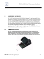
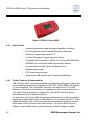
8.1
USB Multilink Universal
The USB Multilink Universal offers an affordable and compact solution for your
development needs, and allows debugging and programming to be accomplished
simply and efficiently. Those doing rapid development will find the USB Multilink
Universal easy to use and fully capable of fast-paced debugging and programming.
Figure 8-2: P&E’s Multilink Universal
P&E Microcomputer Systems, Inc.
35
PROG for ARM® Cortex™-M processors User Manual
8.1.1
8.1.2
Key Features
•
Programming and debugging capabilities
•
Compact and lightweight
•
Communication via high-speed USB 2.0
•
Supported by P&E software, Freescale’s CodeWarrior, and other
third-party software
Product Features & Implementation
P&E’s USB Multilink Universal interface connects your target to your PC and allows
the PC access to the debug mode on Freescale’s Kinetis, ColdFire V1/ColdFire+ V1,
ColdFire V2-4, Qorivva MPC55xx/56xx, Power Architecture PX Series, DSC,
HC(S)12(X), HCS08 and RS08 microcontrollers. It connects between a USB port on a
Windows 2000/XP/2003/Vista/7 machine and a standard BDM or JTAG connector on
the target.
By using the USB Multilink Universal interface, the user can take advantage of the
background debug mode to halt normal processor execution and use a PC to control
the processor. The user can then directly control the target’s execution, read/write
registers and memory values, debug code on the processor, and program internal or
external FLASH memory devices. The Multilink Universal enables you to debug,
program, and test your code on your board.
8.1.3
Software
The USB Multilink Universal interface works with Codewarrior, as well as P&E’s flash
programmer, PROGACMP.
8.2
USB Multilink Universal FX
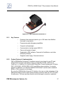
The USB Multilink Universal FX offers a very high-speed development solution that is
still affordable, compact, and allows debugging and programming to be accomplished
simply and efficiently. As with the USB Multilink Universal, those doing rapid
development will find the much speedier USB Multilink Universal FX easy to use and
fully capable of fast-paced debugging and programming.
36
P&E Microcomputer Systems, Inc.
PROG for ARM® Cortex™-M processors User Manual
Figure 8-3: P&E’s Multilink Universal FX
8.2.1
8.2.2
Key Features
•
Extremely fast download speeds (up to 10X faster than Multilink
Universal or equivalent)
•
Programming and debugging capabilities
•
Compact and lightweight
•
Communication via high-speed USB 2.0
•
Can provide power to target
•
Supported by P&E software, Freescale’s CodeWarrior, and other
third-party software
•
Supports certain legacy Freescale devices
Product Features & Implementation
P&E’s USB Multilink Universal FX interface connects your target to your PC and
allows the PC access to the debug mode on Freescale’s Kinetis, ColdFire V1/
ColdFire+ V1, ColdFire V2-4, Qorivva MPC55xx/56xx, Power Architecture PX Series,
DSC, HC(S)12(X), HCS08, RS08, HC16, and 683xx microcontrollers. It connects
between a USB port on a Windows 2000/XP/2003/Vista/7 machine and a standard
BDM or JTAG connector on the target.
By using the USB Multilink Universal FX interface, the user can take advantage of the
background debug mode to halt normal processor execution and use a PC to control
the processor. The user can then directly control the target’s execution, read/write
P&E Microcomputer Systems, Inc.
37
PROG for ARM® Cortex™-M processors User Manual
registers and memory values, debug code on the processor, and program internal or
external FLASH memory devices. The Multilink Universal enables you to debug,
program, and test your code on your board.
8.2.3
Software
The USB Multilink Universal FX interface works with Freescale’s CodeWarrior, as well
as P&E’s flash programmer, PROG for ARM Cortex-M processors.
8.3
Tracelink
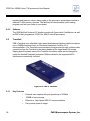
P&E’s Tracelink is an affordable, high-speed development interface which can capture
up to 128MB of external trace on Freescale Kinetis and ColdFire V2-4
microcontrollers. The Tracelink communicates to the processor through a ribbon cable
connection from the Tracelink to the debug header of the target board. By simply
flipping open the plastic case of the Tracelink, the ribbon cable can be changed to
match the desired Freescale processor. Ribbon cables for the supported MCU
families are conveniently included.
Figure 8-4: P&E’s Tracelink
8.3.1
38
Key Features
•
External trace capture with port speeds up to 250MHz
•
128MB of trace storage
•
Ethernet or High-Speed USB 2.0 communications
•
Can provide power to target
P&E Microcomputer Systems, Inc.
PROG for ARM® Cortex™-M processors User Manual
8.3.2
•
Fast performance
•
Multi-voltage support for targets ranging from 1.8 to 5 Volts
•
I/O line clamping for added protection
•
Includes ribbon cables for all supported Freescale MCUs
•
Supported by Freescale’s CodeWarrior
Product Features & Implementation
The Tracelink connects to a host Windows PC via USB or Ethernet. Standard run
control operations such as control of processor execution (run, step, breakpoint), and
read/write of registers and memory are fully supported. This also includes flash
programming support for both internal and external FLASH memory devices.
The main feature of the Tracelink is the ability to capture real-time trace information
from the target processor. This is invaluable for debugging applications where
traditional step/breakpoint methods are simply impractical. In many applications, it is
not possible to halt the target processor without causing the overall system to fail.
Software bugs that are difficult to reproduce and occur infrequently are usually
extremely time-consuming to debug using traditional methods. The Tracelink removes
these limitations, allowing the developer to spend more time finding and fixing bugs,
which ultimately shortens development cycles and time to market.
8.3.3
Software
The Tracelink’s trace capture ability is supported by recent versions of Freescale’s
CodeWarrior software.
8.4
Cyclone MAX
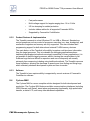
The Cyclone MAX is a more complete solution designed for both development and
production. The Cyclone MAX features multiple communications interfaces (including
USB, Ethernet, and Serial), stand-alone programming functionality, high speed data
transfer, a status LCD, and many other advanced capabilities.
P&E Microcomputer Systems, Inc.
39
PROG for ARM® Cortex™-M processors User Manual
Figure 8-5: P&E’s Cyclone MAX
8.4.1
8.4.2
Key Features
•
Advanced programming and debugging capabilities, including:
•
PC-Controlled and User-Controlled Stand-Alone Operation
•
Interactive Programming via Host PC
•
In-Circuit Debugging, Programming, and Testing
•
Compatible with Freescale’s ColdFire V2-4, Qorivva MPC55xx/56xx,
ARM MAC7xxx, and Kinetis ARM microcontroller families
•
Communication via USB, Serial, and Ethernet Ports
•
Multiple image storage
•
LCD screen menu interface
•
Supported by P&E software and Freescale’s CodeWarrior
Product Features & Implementation
P&E’s Cyclone MAX is an extremely flexible tool designed for debugging, testing, and
in-circuit flash programming of Freescale’s HC(S)12(X), HCS08, RS08, and ColdFire
V1 microcontrollers. The Cyclone MAX connects your target to the PC via USB,
Ethernet, or Serial Port and enables you to debug your code, program, and test it on
your board. After development is complete the Cyclone MAX can be used as a
production tool on your manufacturing floor.
For production, the Cyclone MAX may be operated interactively via Windows-based
programming applications as well as under batch or .dll commands from a PC. Once
loaded with data by a PC it can be disconnected and operated manually in a standalone mode via the LCD menu and control buttons. The Cyclone MAX has over
3Mbytes of non-volatile memory, which allows the on-board storage of multiple
40
P&E Microcomputer Systems, Inc.
PROG for ARM® Cortex™-M processors User Manual
programming images. When connected to a PC for programming or loading it can
communicate via the ethernet, USB, or serial interfaces.
8.4.3
Software
The Cyclone MAX comes with intuitive configuration software and interactive
programming software, as well as easy to use automated control software. The
Cyclone MAX also functions as a full-featured debug interface, and is supported by
Freescale’s CodeWarrior as well as development software from P&E.
P&E’s Cyclone MAX is also available bundled with additional software as part of
various Development Packages. In addition to the Cyclone MAX, these Development
Packages include in-circuit debugging software, flash programming software, a
Windows IDE, and register file editor.
P&E Microcomputer Systems, Inc.
41
PROG for ARM® Cortex™-M processors User Manual
9
PROGRAMMING UTILITIES
The following no-cost programming utilities are available on P&E’s website.
www.pemicro.com, by navigating to Support -> Documentation & Downloads ->
Utilities.
9.1
Serialize
The Serialize utility allows the generation of a .SER serial number description file. This
graphical utility sets up a serial number which will count according to the bounds set
by the user. The .SER file can be called by the PROG flash programmer to program a
serial number into the target.
More information on how to use the Serialize utility can be found on P&E’s website at:
www.pemicro.com/blog/post.cfm/expert-s-corner-programming-serial-numbers-intoflash.
P&E Microcomputer Systems, Inc.
43
PROG for ARM® Cortex™-M processors User Manual
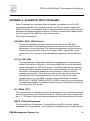
APPENDIX A - ALGORITHM SETUP COMMANDS
Setup Commands are commands that each appear on separate lines of a .ARP
programming algorithm file, starting in column one. They are used to initialize the
target CPU when it is not possible to do so using the enable function, which must first
be loaded into target ram before execution. All setup commands must appear before
the first S record in the .ARP file or they will be ignored.
The setup commands are:
REQUIRES_PROG_VERSION=x.xx/
Sometimes algorithms will require features to be built into the P&E flash
programmer itself. If the algorithm requires a minimum version number of the
programmer, use this command. The interactive programmer will give the user a
warning if the programmer version is not greater than or equal to the version
referenced in this command. The commandline programmer will halt with error
14.
NO_ON_CHIP_RAM
This command has 14 characters and tells the programmer not to perform any
action to turn on the on chip ram. You must provide RAM to run the calibration
routines and load your .ARP file S records. If not deactivated by this command,
the on chip RAM is turned on after all other setup commands are executed. On
chip RAM is automatically enabled in most processor in order to load the
programming algorithm. If your processor has on chip ram and it is turned on
automatically, use this command without any writes to chip select. If your
processor has no on_chip RAM, use this command and follow it with either
WRITE_BYTE, WRITE_WORD or WRITE_LONG in order to turn on chip selects
to enable external RAM. The RAM should be turned on at the location where the
S records in the .CFP file start.
NO_TIMING_TEST
This command has 14 characters and tells the programmer not to evaluate the target
processor speed during the initialization process. Instead, both timing constants are
set to 1. This option is only used when programming timing functions are not needed.
WRITE_LONG=llllllll/aaaaaaaa/
This command has 29 characters. It writes the hex long llllllll to the hex address
aaaaaaaa in the current space. This command is most often used to enable the chip
P&E Microcomputer Systems, Inc.
45
PROG for ARM® Cortex™-M processors User Manual
selects to allow the CPU to see the flash at address 0. By default the debugger
assumes the flash is on CSBOOT. You may also do all sorts of system configuration
with these command.
WRITE_WORD=wwww/aaaaaaaa/
This command has 25 characters. It writes the hex word wwww to the hex address
aaaaaaaa in the current space. This command is most often used to enable the chip
selects to allow the CPU to see the flash at address 0. By default the debugger
assumes the flash is on CSBOOT. You may also do all sorts of system configuration
with these command.
WRITE_BYTE=bb/aaaaaaaa/
This command has 23 characters. It writes the hex byte bb to the hex address
aaaaaaaa in the current space. This command is most often used to enable the chip
selects to allow the CPU to see the flash at address 0. By default the debugger
assumes the flash is on CSBOOT. You may also do all sorts of system configuration
with these command.
BOUNDARY_MASK=mmmmmmmm/
This command has 23 characters. It indicates to the programmer that when buffering
data down to the target, the data may not cross certain boundaries. If a value of
$FFFFFF80 was used, this would indicate to the programmer that only 128 byte
sections may be programming at once (aligned on 128-byte boundaries). This does
not mean that the whole 128 bytes need to be programmed, only that the flash
programmer will split the data up to be programmed in chunks which never cross a
certain boundary. This is very useful for paged memory, or to adhere to block
programming requirements of certain motorola flash.
BLOCKING_MASK=mmmmmmmm/
This command has 23 characters. First it tells the programmer that only full blocks of
data can be programmed into the device and that blocks must occur on a block
boundary. The mask mmmmmmmm is used to select those address lines which occur
within a block. For example, blocks of 8 bytes would have a mask of 00000007. The
buffer provided in the target must in size be an integral multiple of the blocking size in
bytes.
BLANK_MODULE_ONLY
This command has 17 characters. It indicates to the programmer that if a blank byte
46
P&E Microcomputer Systems, Inc.
PROG for ARM® Cortex™-M processors User Manual
address or blank word address is provided they can only be used to enable a blank
module command.
NO_BASE_ADDRESS
or
NO_BASE_ADDRESS=bbbbbbbb/
The 15 character command version tells the prog software to use a base address of 0
and not to ask the user to enter one. The 25 character version is the same except it
sets the base address to bbbbbbbb.
ADDR_RANGE=aaaaaaaa/bbbbbbbb/
Normally the valid flash range is set by the module_length constant in the algorithm
which the programmer then uses to decide how to display memory in the code
window. If not all memory between module_address and
module_address+module_length is valid, this command can be used to override the
default functionality and describe to the programmer what is valid memory which
should be displayed and changed. Note that these addresses are relative to the base
address of the flash. aaaaaaaa is the start address relative to the base address and
bbbbbbbb is the end address relative to the base address.
P&E Microcomputer Systems, Inc.
47
PROG for ARM® Cortex™-M processors User Manual
APPENDIX B - ALGORITHM TABLE ENTRY
Users who wish to make significant modifications to a programming algorithm may need
to modify the table entries in their assembly (.ASM ) file. Table entries provide information
to the PROG software, including what functions are in the algorithm and where they are
located. Each table entry consists of 32 bits and must be in the following order:
Stack Address
Address of the stack during routine execution. The stack is initialized each time
one of the user-supplied routines is called.
Buffer Address
Address of the buffer used to transfer data from the PC to the target. This is data
to be placed into the module.
Buffer Length
Length of available buffer space in bytes. The buffer should be at least 4,096
bytes long in order to accommodate the largest possible S record.
Module Address
The physical address of the beginning of the module to be programmed or
erased.
Module Length
Length of the module to be programmed in bytes.
Blank Bytes Address
The address of a routine to check a block of bytes to see if they are erased. R1
contains the starting address and R2 contains the number of bytes to check.
Checking is done on a byte by byte basis. If R2<>0 on return then an error
occurred at word address R1-1. R2 = 0.
Blank Words Address
The address of a routine to check a block of words to see if they are erased. R1
contains the starting address and R2 contains the number of bytes to check.
Checking is done on a word by word basis. If R2<>0 on return then an error
occurred at word address R1-2.R2 = 0.
Erase Bytes Address
The address of a routine to erase a block of bytes. R1 contains the starting
address and R2 contains the number of bytes to erase. Erasing is done on a byte
P&E Microcomputer Systems, Inc.
49
PROG for ARM® Cortex™-M processors User Manual
by byte basis. R2 = 0.
Erase Long Address
The address of a routine to erase a block of longs. R1 contains the starting
address and R2 contains the number of bytes to erase. Erasing is done on a word
by word basis. If R2<>0 on return an erase error occurred. R2 = 0.
Erade Module Address
The address of a routine which erases the entire module. R1 contains the starting
address to be erased, R2 contains the length in bytes. Returning to PROGACMP
with R2 non zero indicates an error.
Program Bytes Address
The address of a routine which programs a block of bytes residing in the buffer.
R2 contains the length of the block in bytes. R1 contains the starting address at
which they are to be programmed. R3 contains the address of the buffer.
Returning with R2 non zero indicates an error.
Program Words Address
The address of a routine which programs a block of bytes residing in the buffer.
R2 contains the length of the block in bytes. R1 contains the starting address at
which they are to be programmed. R3 contains the address of the buffer.
Returning with R2 non zero indicates an error.
On Volts Address
The address of a routine which turns on the voltages necessary to program/erase
the module. This address must be 0 form PROG for ARM Cortex-M processors.
Off Volts Address
The address of a routine which turns off the voltages necessary to program/erase
the module. This address must be 0 form PROG for ARM Cortex-M processors.
Enable Address
The address of a routine which sets up and enable the module at startup and after
each command is executed. Returning with R2 non zero indicates an error.
Disable Address
The address of a routine which shuts down the module. This address must be 0
form PROG for ARM Cortex-M processors.
Before Read Address
The address of a routine which sets up the module to do a read. R1 contains the
50
P&E Microcomputer Systems, Inc.
PROG for ARM® Cortex™-M processors User Manual
address to be read.
After Read Address
The address of a routine which takes the module out of read mode.
User Function Address
This is an optional user function. It is created with a USER = statement in the
.ARP file and a corresponding address as an extra address in the table. On entry,
R2 is the module length, R1 is the module address, R4 is the user parameter if
any, and R3 is the buffer address. If on return R2<>0 an error occurred.
P&E Microcomputer Systems, Inc.
51