1
LinMot-Talk 6
3.2
Cabling E1200
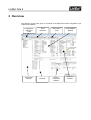
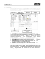
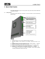
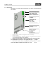
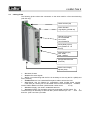
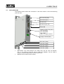
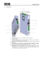
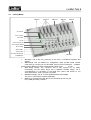
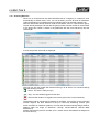
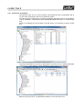
The following picture shows the connectors on the drive used for a first commissioning
(with PC only).
Motor Power Supply (X1)
Motor Phases (X2) (if
present, otherwise on X3)
Motor Signals (X3)
(DSUB 9f)
Signal Supply (X4)
Pin1: GND
Pin2: +24VDC
Pin12: SVE (if present)
Configuration Ethernet
(X15/X16)
RS232 to PC (X19)
Pin3: RS232RX
Pin5: GND
Pin6: RS232TX
X1 Motor Supply, use 48..72 VDC (between PWR+ and PGND).
X2 Motor Phases.
X3 Motor Signals. (Note: the motor phases are not present on this connector.
Thus wire the motor phases in any case to X2).
➢ X4 For a commissioning with the PC it is necessary to wire only the Pin1 (GND),
Pin2 (+24VDC) and, if present, Pin12 save voltage enable (SVE,
+24VDC).
➢ X15/X16 Ethernet: Use a standard RJ45 patch cable to wire to the LAN.
➢ X19 RS232: Use the RS232 PC configuration cable (LinMot article number
0150-2143) to connect your PC via RS232. If the PC has no COM port available,
use the USB to RS232 converter (LinMot article number 01503110).
➢
➢
➢