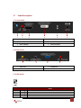
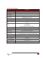
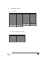
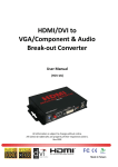
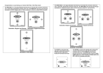
1
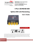
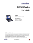
HDMI / DVI to Component / VGA with Audio Converter Model #: C -HDM-COMPVGA © 2010 Avenview Inc. All rights reserved. The contents of this document are provided in connection with Avenview Inc. (“Avenview”) products. Avenview makes no representations or warranties with respect to the accuracy or completeness of the contents of this publication and reserves the right to make changes to specifications and product descriptions at any time without notice. No license, whether express, implied, or otherwise, to any intellectual property rights is granted by this publication. Except as set forth in Avenview Standard Terms and Conditions of Sale, Avenview assumes no liability whatsoever, and disclaims any express or implied warranty, relating to its products including, but not limited to, the implied warranty of merchantability, fitness for a particular purpose, or infringement of any intellectual property right. Reproduction of this manual, or parts thereof, in any form, without the express written permission of Avenview Inc. is strictly prohibited. www.avenview.com 1 Table of Contents Section 1: Getting Started ...................................................................................................................... 3 1.1 Important Safeguards ............................................................................................................ 3 1.2 Safety Instructions ................................................................................................................. 3 1.3 Regulatory Notices Federal Communications Commission (FCC) ......................................... 4 1.4 Introduction ........................................................................................................................... 4 1.5 Package Contents................................................................................................................... 6 1.6 Before Installation.................................................................................................................. 6 1.7 Panel Description ................................................................................................................... 7 1.7.1 Front Panel ............................................................................................................................ 7 1.7.2 Rear Panel ............................................................................................................................. 7 1.7.3 DIP Switch.............................................................................................................................. 7 1.8 Installation ............................................................................................................................. 8 Section 2: Specifications......................................................................................................................... 9 2.1 Supported Resolutions......................................................................................................... 10 2.1.1 DVI or VGA.................................................................................................................... 10 2.1.2 HDMI or Component Video (YPbPr) ............................................................................. 10 www.avenview.com 2 Section 1: Getting Started 1.1 Important Safeguards Please read all of these instructions carefully before you use the device. Save this manual for future reference. What the warranty does not cover 1.2 Any product, on which the serial number has been defaced, modified or removed. Damage, deterioration or malfunction resulting from: Accident, misuse, neglect, fire, water, lightning, or other acts of nature, unauthorized product modification, or failure to follow instructions supplied with the product. Repair or attempted repair by anyone not authorized by us. Any damage of the product due to shipment. Removal or installation of the product. Causes external to the product, such as electric power fluctuation or failure. Use of supplies or parts not meeting our specifications. Normal wear and tear. Any other causes which does not relate to a product defect. Removal, installation, and set-up service charges. Safety Instructions The C-HDM-COMPVGA, HDMI / DVI to Component / VGA with Audio Converter has been tested for conformance to safety regulations and requirements, and has been certified for international use. However, like all electronic equipment’s, the C-HDM-COMPVGA should be used with care. Read the following safety instructions to protect yourself from possible injury and to minimize the risk of damage to the unit. Do not dismantle the housing or modify the module. Dismantling the housing or modifying the module may result in electrical shock or burn. Refer all servicing to qualified service personnel. Do not attempt to service this product yourself as opening or removing housing may expose you to dangerous voltage or other hazards Keep the module away from liquids. Spillage into the housing may result in fire, electrical shock, or equipment damage. If an object or liquid falls or spills on to the housing, unplug the module immediately. Have the module checked by a qualified service engineer before using it again. Do not use liquid or aerosol cleaners to clean this unit. Always unplug the power to the device before cleaning. www.avenview.com 3 1.3 Regulatory Notices Federal Communications Commission (FCC) This equipment has been tested and found to comply with Part 15 of the FCC rules. These limits are designed to provide reasonable protection against harmful interference in a residential installation. Any changes or modifications made to this equipment may void the user’s authority to operate this equipment. 1.4 Introduction Avenview C-HDM-COMPVGA HDMI / DVI to Component / VGA with Audio Converter provides an easy and instant approach for converting digital HDMI and/or digital DVI video signal to Component or VGA with digital S/PDIF or analog stereo audio. With C-HDM-COMPVGA converter, HDMI and/or DVI based devices such as DVD players, PS3, camcorders, set-top-boxes or PC can connect to Component or VGA TV or projector at low cost. The embedded HDMI / DVI selector switches between HDMI and DVI input sources. - HDMI compatible HDMI video input supports up to 1080p resolution Supports HD (1080i / 720p) component video output Supports up to UXGA PC video output Coaxial S/PDIF audio input Stereo analog audio input Front panel LED indicators and push button for switch between DVI or HDMI sources Easy installation www.avenview.com 4 www.avenview.com 5 1.5 Package Contents Before you start the installation of the converter, please check the package contents. - C-HDM-COMPVGA VGA to Component Y Adapter Power Adapter (+5VDC, 2A) x1 x1 x1 - User’s Manual x1 1.6 Before Installation Put the product in an even and stable location. If the product falls down or drops, it may cause an injury or malfunction. Don’t place the product in too high temperature (over 50°C), too low temperature (under 0°C) or high humidity. Use the DC power adapter with correct specifications. If inappropriate power supply is used then it may cause a fire. Do not twist or pull by force ends of the optical cable. It can cause malfunction. Note: This Converter is NOT-HDCP compatible. This unit should not be connected to HDCP Devices such as STP (Cable/Sat Boxes) and Blu ray/DVD players etc………… www.avenview.com 6 1.7 Panel Description 1.7.1 Front Panel 1 2 3 4 5 6 1. DIP Swtich 2. HDMI / DVI Switch Button 3. HDMI Input 4. DVI / VGA Input 5. Power Indicator 6. Power Connector 1.7.2 Rear Panel 1 2 3 4 1. S/PDIF OUT 2. STEREO OUT 3. COMPONENT / VGA OUT 4. VGA / COMPONENT Switch Button 1.7.3 DIP Switch PIN # 1 1 2 2 Mode ON OFF ON OFF Learn EDID from VGA socket and save EDID to HDMI socket Write back default EDID to HDMI socket Learn EDID from VGA socket and save EDID to DVI socket Write back default EDID to DVI socket www.avenview.com 7 1.8 Installation To setup Avenview C-HDM-COMPVGA follow these steps for connecting to a device: 1. 2. 3. 4. 5. 6. 7. 8. Power off display source such as DVD Player, Set-top box etc Connect your HDMI and/or DVI source to HDMI input and/or DVI input Connect S/PDIF or Stereo Audio source to RCA Jack or 3.5mm Jack Connect VGA/Component Y cable to C-HDM-COMPVGA Connect other end of VGA/Component Y cable to VGA or Component input of display Plug in 5V DC power cord to power jack of C-HDM-COMPVGA Power on C-HDM-COMPVGA converter Power on HDMI and/or DVI source and display with VGA or Component input. S/PDIF format is dependent on the embedded digital audio part in the HDMI stream. The S/PDIF receiver must be able to recognize the input S/PDIF format. C-HDM-DVIA only separates the digital audio in HDMI stream and bypasses this decoded audio to the output. This version does NOT support 8 Channel analog audio applications S/PDIF audio input can support 2 out of 8 channel audio inputs. S/PDIF audio only supports 48 KHz audio sample rate. www.avenview.com 8 Section 2: Specifications Item Units Unit Description HDMI Compliance DVI Compliance Video Bandwidth Video Support Audio Support Input TMDS Signal Input DDC Signal Input Output HDMI Connector DVI Connector VGA Connector RCA Connector 3.5mm Audio Connector Switch Control DIP Switch Dimensions (L x W x H) Power Supply Power Consumption Description C-HDM-COMPVGA HDMI / DVI to Component / VGA with Audio Converter HDMI 1.2a DVI 1.1 Single Link: 165MHz (4.95Gbps) Single Link: 1080p 60, WUXGA (1920x1200@60Hz) Component Video: 720p / 1080i Stereo Audio 1.2 Volts (peak-to-peak) 5 Volts (peak-to-peak, TTL) 1 x HDMI 1 x DVI 1 x VGA 1 x RCA digital Audio 1 x 3.5mm analog Audio Component through VGA to Component Adapter Type A (19 pin female) DVI-I (29-pin female digital only) HD-15 (15-pin D-sub female) Coaxial S/PDIF Digital Audio (PCM 48kHz) Analog Stereo Audio 2 x Push Button (1. HDMI / DVI Input button / 2. VGA / Component Output button) 2-pin for EDID learning 5” X 3.9” x 1.1” 5V 2A DC 4 Watts (max) Environmental Operating Temperature Storage Temperature Relative Humidity 32˚ ~ 104˚F (0˚ to 40˚C) -4˚ ~ 140˚F (-20˚ ~ 60˚C) 20~90% RH (no condensation) www.avenview.com 9 2.1 Supported Resolutions 2.1.1 DVI or VGA Supported Mode Resolution Supported Mode Resolution VESA VESA VESA VESA VESA VESA VESA VESA VESA VESA VESA VESA VESA 640x400 @85Hz 720x400 @85Hz 640x480 @60Hz 640x480 @72Hz 640x480 @75Hz 640x480 @85Hz 800x600 @60Hz 800x600 @72Hz 800x600 @75Hz 800x600 @85Hz 1024x768 @60Hz 1024x768 @75Hz 1024x768 @85Hz VESA VESA VESA VESA VESA VESA VESA VESA VESA VESA VESA VESA 1152x864 @60Hz 1152x864 @75Hz 1152x864 @55Hz 1280x768 @60Hz 1280x768 @75Hz 1280x768 @85Hz 1280x960 @60Hz 1280x960 @85Hz 1280x1024 @60Hz 1280x1024 @85Hz 1600x1200 @60Hz 1920x1200 @60Hz 2.1.2 HDMI or Component Video (YPbPr) Supported Mode Resolution EIA EIA EIA EIA NTSC PAL 720x480p @59.94 (60)Hz 720x576p @ 50Hz 1280x720p @59.94 (60)Hz 1920x1080i @59.94 (60)Hz 712x484 702x574 www.avenview.com 10 Notice 1. Only HDMI enabled TV sets with under-scan/over-scan support, the full active video can be accurately displayed. Some HDMI equipped TV sets may not support this feature. If under-scan/over-scan* is NOT supported, the top, bottom, left and right border of the active video may be screened, and the S/PDIF audio may not sound right. 2. Analog stereo audio can merely support 2-channel audio. This version does NOT support 8-channel analog audio applications. 3. S/PDIF audio input supports the main 2-channel audio input 4. S/PDIF supports only 48kHz audio sample rate. Other than this rate, the input digital audio should be adjusted to 48kHz in order to get audio signal correctly sent . The under-scan mode displays the full video frame, which reveals content on the edge that is recorded. In over-scan, the field monitor zooms in to the area that would be visible on most televisions. Set the field monitor to under-scan if your video will be viewed on a computer monitor or shown with a projector and also to look for light stands, microphones, and other unwanted objects on the edges of your shot. Set it to over-scan to see how the video will look on a television. www.avenview.com 11 Disclaimer While every precaution has been taken in the preparation of this document, Avenview Inc. assumes no liability with respect to the operation or use of Avenview hardware, software or other products and documentation described herein, for any act or omission of Avenview concerning such products or this documentation, for any interruption of service, loss or interruption of business, loss of anticipatory profits, or for punitive, incidental or consequential damages in connection with the furnishing, performance, or use of the Avenview hardware, software, or other products and documentation provided herein. Avenview Inc. reserves the right to make changes without further notice to a product or system described herein to improve reliability, function or design. With respect to Avenview products which this document relates, Avenview disclaims all express or implied warranties regarding such products, including but not limited to, the implied warranties of merchantability, fitness for a particular purpose, and non-infringement. www.avenview.com 12