1
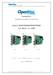
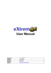
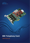
MAGIC-TDAS 03-04
000220/RPaoletti
The MAGIC Level 2 Trigger
A User’s Manual
R. Paoletti
<[email protected]>
Version 1
June 16, 2003
Abstract
This document is the user’s manual for the MAGIC Level 2 Trigger. The interface
program features are described and details on the trigger programming are given.
Contents
1 Introduction
2
2 Level 1 Trigger
3
3 Level 2 Trigger
3.1 The SMART Boards . . .
3.2 The PRESCALER Board
3.3 The SCALER Board . . .
3.4 The DIGITAL I/O Board
.
.
.
.
.
.
.
.
.
.
.
.
.
.
.
.
.
.
.
.
.
.
.
.
.
.
.
.
.
.
.
.
.
.
.
.
.
.
.
.
.
.
.
.
.
.
.
.
.
.
.
.
.
.
.
.
.
.
.
.
.
.
.
.
.
.
.
.
.
.
.
.
.
.
.
.
.
.
.
.
.
.
.
.
4 Calibrations
3
4
6
8
9
9
5 Trigger Rates
10
6 The L2T Interface Program
10
7 Programming L2T
7.1 The Main Menu . . . . . . . . . . . . . . . . . . . . . . . . . . .
7.2 The SMART Menu . . . . . . . . . . . . . . . . . . . . . . . . .
7.3 The PRESCALER Menu . . . . . . . . . . . . . . . . . . . . .
12
13
14
15
1 Introduction
1
2
Introduction
The trigger system of the MAGIC telescope is made by:
• a Level 1 Trigger (L1T), that looks for fast coincidences of next-neighbours pixels;
• a Level 2 Trigger (L2T) that performs a more sophisticated analysis of the shower image.
The trigger area is partially covering the inner camera surface composed by 397 photomultipliers, also
called pixels. In order to ensure a full efficiency at Level 1 even for 5 next neighbour pixels, the trigger
cells are overlapping as shown in figure 1.
A set of 37 pixels is called macrocell, the unit for the trigger system. The L1T system is based on this
segmentation and its logic is defined as a combination of the macrocell pixels. One pixel out of 37,
the “blind pixel”, is not wired into the trigger logic, so the macrocell logic is built on 36 pixels. The
blind pixel is shown as a solid hexagon in figure 1 and marked as “X” in figure 3.
Figure 1: The trigger coverage on the MAGIC camera.
2 Level 1 Trigger
3
bit data
0 0
1 global L1 trigger
2 TBD
3 TBD
4 TBD
5 TBD
6 TBD
7 TBD
calibration
1
TBD
TBD
TBD
TBD
TBD
TBD
TBD
Table 1: Definition of the trigger word (preliminary).
The whole trigger system architecture is sketched in figure 2. On the leftmost side the 19 L1T cells
are visible. Upon a valid L1T, the digital information is transferred to the L2T that is arranged in a
tree structure in order to transfer the information to next layers and to apply topological cuts on the
shower image. The L2T system does not output a single signal but an 8-bit word where the trigger
information can be coded.
At the time of this writing, the trigger word coding is not defined. A preliminary definition is in
table 1.
2
Level 1 Trigger
The L1T boards are custom electronic boards housed in the trigger rack. The signals coming from
the discriminators are fed into the L1T backplane (rear of the crate) according to the scheme that is
sketched on the front panel of the L1T crate. Each cable transports 8 LVDS differential signals.
The L1T boards perform a logic combination of the input signals to look for clusters of 2, 3, 4 or 5
neighbour pixels, according to TTL levels on the “fold selector inputs”, located on the front panel.
The fold selection is done by the L2T interface as explained in section 3.4.
The DB9 connector on the L1T boards outputs the 2, 3, 4 and 5 logic combinations that are sent to
the TPU (Trigger Processing Unit), located on top of the trigger rack.
The purpose of the TPU board is twofold:
• to select the fold combination for rates measurement;
• to fan out the fold selection levels to the L1T boards.
The Global OR of the L1T boards is sent to a LEMO-00 connector as a TTL signal.
DO NOT use this signal as an alternative trigger source because the level and timing are
not compatible with the FADC system.
3
Level 2 Trigger
The L2T is an asynchronous system made by electronic boards called SMART, with on-board Look
Up Tables (LUTs), arranged in a tree-like structure, see figure 2. In this section we review the
3.1 The SMART Boards
Figure 2: Scheme of the L2T system. The L1T boards are shown on the left.
characteristics of the electronic boards. A description of the trigger implementation can be found
in [3].
3.1
The SMART Boards
The SMART is a 6U board, mechanically and electrically compatible with the VME bus. The input
signals are LVDS levels.
The 36 input signals are split in three 12-bit words. Every LUT outputs a 5 lines bus. The buses
coming from the three LUTs are grouped in a 15 bit bus as the input of the fourth LUT.
The contents of a LUT are downloaded by the L2T interface program.
The address scheme used for the SMART boards is reported in the following table:
The first 19 SMART boards are located on the bottom VME crate of the trigger rack. There is a
one-to-one correspondence between these SMARTs and the L1 boards.
4
3.1 The SMART Boards
5
SPECIFICATIONS
VME access
Address
Package
Memory
Depth
INPUT SIGNALS
INPUT SIGNALS LVDS
OUTPUT SCALER TTL
TRG OUT
INTERNAL REGISTERS
LUT1
LUT2
LUT3
LUT4
PATTERN
A24/D16
dip-switches
6U
three 12-bit SRAM, one 15-bit SRAM
3*4096 bytes, 32768 bytes
36 differential LVDS levels, SCSI HD connector
9 channels TTL level, 20 pin header
differential ECL signal
Base address for LUT #1
Address: BASE+0x00000000, R/W, D16
Base address for LUT #2
Address: BASE+0x00010000, R/W, D16
Base address for LUT #3
Address: BASE+0x00020000, R/W, D16
Base address for LUT #4
Address: BASE+0x00030000, R/W, D16
Output pattern register
Address: BASE+0x00040000, W, D16
Writing an 8-bit word into the PATTERN register will produce
the same pattern on the output connector. Used for debugging.
Table 2: Specifications for the SMART board
SMART
#1
#2
...
# 14
# 15
# 16
# 17
...
# 23
# 24
Address (HEX)
0x0010 0000
0x0020 0000
...
0x00E0 0000
0x00F0 0000
0x0008 0000
0x0018 0000
...
0x0078 0000
0x0088 0000
Table 3: Address scheme of the SMART boards
3.2 The PRESCALER Board
6
Figure 3: Pinout inside a SMART
3.2
The PRESCALER Board
The PRESCALER board is used in the MAGIC telescope to prescale the triggers coming from the
L2T in order not to fill the maximum DAQ bandwidth. Its characteristics are:
• large prescale interval (0 - 65535)
• capability to handle trigger and calibration signals
The PRESCALER is a 6U board, mechanically and electrically compatible with the VME bus.
• REGISTER - these registers contain the prescaler values for the 8 input channels.
• ENABLE - This register contains the enable mask for the 8 input channels. Writing 0 in a given
position disables the corresponding channel. Writing 1 will enable the channel.
bit
channel
15 · · · 8
X
7
7
6
6
5
5
4
4
3
3
2
2
1
1
0
0
3.2 The PRESCALER Board
SPECIFICATIONS
Package
VME access
Address
INPUT SIGNALS
INPUTS
BUSY
WR ZERO
OUTPUT SIGNALS
TRGOUT
WR FIFO
WR FIFO
WR FIFO
OUTPUT PATTERNS
INTERNAL ADDRESSES
REGISTER
ENABLE
RESET
CLEAR
7
6U
A24/D16
dip-switches
8 channels LVDS, one 20 pin 3M-3WALL connector
ECL signal, LEMO-B connector
ECL signal , LEMO-B connector
ECL signal, LEMO-B connector
ECL signal, LEMO-B connector
ECL signal, LEMO-B connector
ECL signal, LEMO-B connector
16 channels LVDS, two 40 pins 3M-3WALL connectors
Address:
Address:
Address:
Address:
BASE+0x0002*n, R/W, D16 (n = 0, 7)
BASE+0x0010, R/W, D16
BASE+0x0012, WRITE ONLY, D16
BASE+0x0014, WRITE ONLY, D16
Table 4: Specifications for the PRESCALER board
3.3 The SCALER Board
SPECIFICATIONS
Package
Count Accuracy
Time Accuracy
VME access
Address
Memory
INPUT SIGNALS
INPUTS
VETO
EXT CLOCK
CLEAR
TEST
8
6U VME board
32 bits equivalent to 4 Giga counts max.
20 ns, time window selected by a 32 bit word
A32/D32, A24/D16
rotary-switches
double buffer
80 channels LVDS/TTL, two 3M-3WALL connectors
LVDS signal, LEMO-B connector
LVDS signal, LEMO-B connector
LVDS signal, LEMO-B connector
LVDS signal, LEMO-B connector
Table 5: Specification for the SCALER board
• RESET - Accessing this register will reset the count registers.
• CLEAR - Accessing this register will clear the prescaler registers.
3.3
The SCALER Board
The SCALER board is used in the MAGIC telescope to measure the pixels trigger rates and to monitor
the dead and live time of the experiment. Its features are:
• 80 input channels (LVDS/TTL)
• accurate rates count (32 bits, 4 Giga counts max)
• dead and live time measurement (64 bit words)
• counts measurement in a variable time interval in 20 ns bins (for a 50 MHz internal clock)
The SCALER is a 6U board, mechanically and electrically compatible with the VME bus. The
input signals can be either LVDS or TTL levels. They can be defined by soldering the appropriate
converters/drivers on the board. The VME addressing is A24/D16 for control registers and A32/D32
for data registers.
The board accepts signals on its front panel.
• INPUTS - the 80 inputs are divided in two connectors, 3M-3432-3Wall/3Wall. The inputs can
be either LVDS or TTL levels. Depending on the choice, LVDS translators or TTL buffers are
mounted on board.
• VETO - is the BUSY signal coming from the FADC system. When this signal is high, counts
are disabled.
• EXT CLOCK - is a strobe signal used in place of the internal timing signal given by the 50
MHz oscillator. An internal register is used to select between internal and external trigger.
3.4 The DIGITAL I/O Board
9
SPECIFICATIONS
Package
VME access
Address
INTERNAL REGISTERS
3U VME board
A16/D16, A16/D8
dip-switches
Table 6: Specifications for the DIGITAL I/O board
fold
2
3
4
5
pattern
(binary)
001
010
011
100
description
2
3
4
5
NN
NN
NN
NN
logic
logic
logic
logic
Table 7: Logic for the L1 fold selection
• CLEAR - is an external signal that resets all the counters
• TEST - increments all the counters regardless of the VETO signal. Mainly used for debugging.
This board is currently being designed and its internal registers are not yet defined.
Open question. If the dead and live time have to go into the data stream, this information has to be
latched with the trigger by the Digital Modules. This means that one of the SCALER boards has to
be programmed as an output register, i.e. it has to output the register contents on the 3M connectors
upon every EXT CLOCK, in this case the L2 trigger.
The register contents (64 bits) require four DMs for the dead time and other four for the live time
information.
3.4
The DIGITAL I/O Board
The DIGITAL I/O board is a commercial VME board (VMIC xxx). It is a double parallel port board,
with I/O capability and internal timers. It is used in the L2T framework as a digital output board to
drive the fold selector connector on the L1 boards. The board outputs a TTL pattern that goes to
the “Fold Selector” input of the TPU board (see table 7).
4
Calibrations
Twelve lines of the L2T system are available for calibration purposes (figure 2). The interface between
the L2T system and the calibration lines is given by the L2T SMART interface board, called L2Link.
Calibrations are merged together with the outputs of SMARTs # 20, 21, 22 and 23 into the last
SMART board (#24).
5 Trigger Rates
10
signal
signal
signal
signal
signal
signal
1
2
3
4
5
6
(+)
(+)
(+)
(+)
(+)
(+)
NC
NC
NC
NC
pin pin
1
2
3
4
5
6
7
8
9
10
11
12
13
14
15
16
17
18
19
20
signal
signal
signal
signal
signal
signal
NC
NC
NC
NC
1
2
3
4
5
6
(-)
(-)
(-)
(-)
(-)
(-)
Table 8: Connector pinout for calibration signals # 1-6. A similar scheme is valid for calibration
lines # 7-12.
The calibration signals have to be made available to the L2T system as LVDS levels on two connectors
of the L2link board. They travel through two 20-lines twisted pair flat cables and connect to the
L2Link with a polarized 2 × 10 header connector according to the scheme described in table 8. This
plug connector goes into a receptacle similar to that one used for the Digital Modules [2].
Any signal on pins 13-14 and 15-16, marked as NC, can be sent to an output connector and to scalers
for calibration monitor. If you are not interested in this feature just leave them unconnected.
5
Trigger Rates
The trigger rates are measured by a commercial VME board (CAEN V791?) accepting 32 LVDS input
signals. It is used mainly to measure the rates of the L1T macrocells. These signals are coming from
the L1 TPU board, located on top of the trigger rack.
A list of the trigger rates reported to Central Control is contained in table 9. This definition is
used in the commissioning phase and has to be cosidered as temporary. It may change
in the future.
6
The L2T Interface Program
To start the program do the following:
1. Log on the trigger machine (PC11) as trigger.
2. Go in the programs directory
cd programs
3. start the trigger interface
trigger
or
./vmetest.
6 The L2T Interface Program
pin
1
2
···
18
19
20
21
22
23
24
25
26
27
28
29
30
31
32
11
description
L1T macrocell # 1
L1T macrocell # 2
···
L1T macrocell # 18
L1T macrocell # 19
L2T prescaled triggers
L2T unprescaled triggers # 1
calibration # 1- PED
calibration # 2 - CAL
calibration # 3 - PIND
not used
not used
not used
not used
not used
not used
not used
not used
Table 9: Temporary definition of the trigger rates list
7 Programming L2T
12
The interface is based on a kernel program which performs all basic operations on the VME boards.
When it was created, a long time ago, this program was named vmetest. The program interface has
changed a little during the time but the kernel program has remained the same along with its name.
The program can work in stand-alone mode or CC mode, waiting for commands from the Central
Control via TCP sockets. For more informations about the communication protocol between the L2T
and Central Control see [1].
Under normal circumstances, the users should interact with the L2T via the Central
Control only.
7
Programming L2T
This section describes the details of the L2T programming.
Experts only are allowed to use this program and to change configuration files. A misuse
of this program may lead to malfunctions in the trigger system.
The trigger interface is a C program based on simple actions called verbs. A menu is a collection of
verbs. The list of verbs can be obtained by typing a question mark (?) at the menu prompt. A verb
can be shortened as long as the word is not ambiguous. Several verbs can be inserted in a text file
called macro.
The definition of menus are contained in the file vmetest define.uic.
At startup the programs executes a macro file called vmetest init.uic.
An example of the startup macro file is:
!
! This is vmetest_init.uic
!
set
log_path log
log_file on
table_path tables
async yes
HostName pc1.magic.iac.es
HostNo 8000
PortNo 8001
status idle
return
!
smart
init
select 15
table
sp 0 1 sp 1 1 sp
sp 6 1 sp 7 1 sp
sp 12 1 sp 13 1 sp
sp 18 1 sp 19 1 sp
sp 24 1 sp 25 1 sp
sp 30 1 sp 31 1 sp
2
8
14
20
26
32
1
1
1
1
1
1
sp
sp
sp
sp
sp
sp
3
9
15
21
27
33
1
1
1
1
1
1
sp
sp
sp
sp
sp
sp
4
10
16
22
28
34
1
1
1
1
1
1
sp
sp
sp
sp
sp
sp
5
11
17
23
29
35
1
1
1
1
1
1
7.1 The Main Menu
13
out f 0 0 0
print
return
return
!
prescaler
address f000 return
The vmetest init.uic macro file is used to set default values for the program. Direct actions on
VME are not expected to be written in this file in order not to perturb the trigger system state.
This allows to run more than one program without initial interference on the system, e.g. to perform
remote monitoring.
7.1
The Main Menu
The list of verbs available from the main menu is:
-------------------------------------------------------------------------------Trigger Main Menu
1
2
3
4
5
6
7
8
9
10
11
12
13
14
15
16
17
18
19
20
[CONNECT]
[DISCONNECT]
[START]
[STOP!]
[LOADT]
[RATES]
[RATE!]
[RATIM]
[LOCK!]
[ULOCK]
[ADIOS]
[SET]
[SMART]
[PRESCALER]
[VME]
[LOOP]
[MESSAGE]
[SYSTEM]
[WAIT]
[EXIT]
Connect to the L2T system
Disconnect from the L2T system
Enable triggers
Disable trigger
Load trigger table
Turn on trigger reports
Turn off trigger reports
Set trigger reports interval
Lock the L2T control program
Unlock the L2T control program
Disconnect the L2T system from CC
Set Program Parameters
Invoke Smart Menu
Invoke Prescaler Menu
Invoke VME Menu
Loop on macro
Output a Message
Exec system commands
Wait some time
Back to Shell
Here is a brief explanation of the basic verbs.
7.2 The SMART Menu
CONNECT
DISCONNECT
START
STOP!
LOADT
RATES
RATE!
LOCK
ULOCK
SMART
PRESCALER
7.2
14
connects the interface to host name and port number
disconnects the interface from the host
enable triggers (executes the macro tables/START TRIGGERS.uic)
disables trigger (executes the macro tables/STOP TRIGGERS.uic)
used to load a trigger table, e.g. load default
starts the trigger rate reports on the trigger console
stops the trigger rate reports on the trigger console
locks the trigger console, the program listens for commands from the Central Control
the program will not execute commands coming from the Central Control
will invoke the SMART menu to perform actions on the boards. See next sections.
will invoke the PRESCALER menu to perform actions on the boards. See next sections.
The SMART Menu
The list of verbs available from the SMART menu is:
-------------------------------------------------------------------------------Smart Menu
1
2
3
4
5
6
7
8
9
10
11
12
13
14
15
16
17
18
19
20
[SELECT]
[ADDRESS]
[INIT]
[CLEAR]
[PATTERN]
[CHECK]
[LUT]
[INPUTS]
[OUTPUTS]
[TABLE]
[DEBUG]
[PARSE]
[PROGRAM]
[FILL]
[LOGIC]
[DOWNLOAD]
[DUMP]
[PSSIZE]
[SHOW]
[RETURN]
Select SMART
Set SMART Address
Init the SMART Board
Clear the SMART Board
Output a pattern
Enable/Disable Clear Check
Select the LUT memory
Define the input names
Define the output names
Define the logic strings
Turn debugging ON/OFF
Parse the logic strings
Program the TALU Board
Fill memories
Program logic into the TALU Board
Download file into the TALU Board
Dump memory contents to file
Apply pseudo size cuts
Show the TALU Contents
Back to Main Menu
The SMART menu can be used to mask trigger macrocells. This can be accomplished by clearing the
contents of the corresponding SMART board. In this way, the macrocell will not issue triggers. For
example, to mask macrocell # 15 from the trigger logic type:
STOP
SMART
SELECT 15
7.3 The PRESCALER Menu
15
CLEAR
RETURN
START
Always STOP the trigger before any change in the trigger configuration. This is necessary to avoid
spurious trigger to be generated when the VME access is going on. The triggers will be stopped at
PRESCALER level.
The commands can be entered in a more compact way, i.e.
STOP
SMART SELECT 15 CLEAR RETURN
START
When the mask is no more needed you can restore the original trigger table, e.g.:
STOP
LOAD DEFAULT
START
7.3
The PRESCALER Menu
The list of verbs available from the PRESCALER menu is:
-------------------------------------------------------------------------------PRESCALER Menu
1
2
3
4
5
6
7
8
[ADDRESS]
[REG_READ]
[REG_WRITE]
[ENABLE_READ]
[ENABLE_WRITE]
[CLEAR]
[RESET]
[RETURN]
Specify Prescaler VME Address
Read Prescaler Register
Write Prescaler Register
Read Prescaler Enable Mask
Write Prescaler Enable Mask
Clear the Prescaler Registers
Reset the Prescaler Counters
Back to Main Menu
This menu can be used to change prescale factors. The prescale registers are a 16 bit word, so the
maximum factor that can be downloaded in every register is 65535. For example, to set a prescale
factor of 1000 on trigger bit # 0:
STOP
PRESCALER
REG_WRITE 0 1000
RESET
RETURN
START
There is a specific sequence of operations to perform in order to arm the prescaler.
References
16
1. STOP the triggers, by writing ENABLE WRITE 0
2. CLEAR the prescale registers
3. change configuration. E.g. you can load different prescale factors
REG_WRITE
REG_WRITE
REG_WRITE
REG_WRITE
REG_WRITE
REG_WRITE
REG_WRITE
REG_WRITE
0
1
2
3
4
5
6
7
1
10
100
1000
1
255
1024
4096
4. RESET the prescale counters, to start the prescaler from a known initial state
5. START the trigger, by writing ENABLE WRITE hex mask
References
[1] MAGIC-TDAS 00-07
The control system of the MAGIC telescope
J. Cortina et al.
[2] MAGIC-TDAS 02-07, 020717/JCortina
Specifications of the digital DAQ modules and their digital inputs
J.A.Coarasa, J.Cortina, F.Goebel, R.Paoletti, R.Stiehler, N.Turini, 17 July 2002
[3] MAGIC-TDAS 02-12, 021115/AStamerra
NSB Rejection with the level 2 trigger
A.Stamerra, 15 November 2002