1
Table of Contents
Overview .................................................................................................................... 1
Features ..................................................................................................................... 1
Applications............................................................................................................... 1
Hardware requirement .............................................................................................. 1
Card dimensions .................................................................................................. 1
Hardware Setting....................................................................................................... 2
Port & Jumper Identification..................................................................................... 2
NT or TE Mode Selection ........................................................................................ 5
Terminating the NT Mode Line ................................................................................. 5
Onboard Power for NT Mode ................................................................................... 5
Software Installation ................................................................................................. 5
Using Dahdi ............................................................................................................. 6
Using mISDN ........................................................................................................... 8
Software Configuration............................................................................................. 9
Using Dahdi ............................................................................................................. 9
Using mISDN ......................................................................................................... 11
Enabling Echo Cancellation ................................................................................... 13
Test Configuration .................................................................................................. 13
Using Dahdi ........................................................................................................... 13
Using mISDN ......................................................................................................... 15
Reference ................................................................................................................. 17
BRI Card User Manual – Version 1.0
Overview
Allo.com digital cards are telephony PCI & PCI-e cards used for open source
Asterisk based systems. Allo.com CB400P & CB400E are four ports ISDN Basic
Rate Interface line termination PCI & PCI-e cards respectively. CB200P & CB200E
are two ports ISDN Basic Rate Interface line termination PCI &PCI-e cards
respectively.
Features
•
•
•
•
•
•
Capable of serving as Terminal Equipment (TE) or as Network Termination
(NT) device on each independent port
Supports the ETSI standard using CPE-PTP (Point-to-Point), CPE-PTMP
(Point-to-Multipoint), NET-PTP (Point-to-Point), and NETPTMP (Point-toMultipoint)
DTMF detection on all B-channels
Suitable for 3.3 volts and 5.0 volts 32 bit PCI 2.2 slots & PCI-e 1.0 slots
Onboard multi NT power feeding circuit
Optional Hardware echo cancellation module
Applications
•
•
•
•
•
•
ISDN BRI IP PBX
Voice over IP BRI termination gateways
ISDN Least Cost Routers
Traditional Calls/VoIP Calls Conference
IVR system
ISDN Test Equipment
Hardware requirement
Least recommended hardware configuration
• 1.6-GHz Pentium IV
• 512 MB RAM
• 3.3V or 5V 32bit PCI slot (2.2) / PCI-e 1x slots (1.0a)
Card dimensions
CB400P & CB200P: 95 mm (height) ×140.61mm (Length)
CB400E & CB200E: 98.4 mm (height) × 140 mm (Length)
WWW.ALLO.COM
Page 1
BRI Card User Manual – Version 1.0
Hardware Setting
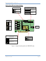
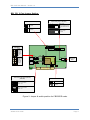
Port & Jumper Identification
CB400P & CB400E cards have four RJ45 ports. CB200P & CB200E cards have two
RJ45 ports. Each port can be configured as either TE or NT operation. The ports are
numbered in sequence from one to four. The bottom port is Port 1 and the top port is
Port 4. See Figure 1 & 2 for appropriate identification of these ports. TE/NT
configuration on the board for each port, should match with software configuration.
The following explains the jumpers, connectors and switches:
For CB400P and CB400E
J1 - J16
SW6
SW1 – SW4
P6
P7-P10
P3,P4
Group of 4 Jumpers for TE/NT Mode setting
Pull up / Pull down switch for TE/NT Mode setting.
DIP Switches for Termination in NT Mode
SMPS power connector ((Used in NT mode)
Power feeding jumpers
Hardware echo cancellation connectors
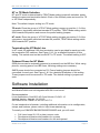
For CB200P and CB200E
J1 - J8
SW6
SW1 – SW2
P6
P7-P8
P3,P4
Group of 4 Jumpers for TE/NT Mode setting
Pull up / Pull down switch for TE/NT Mode setting.
DIP Switches for Termination in NT Mode
SMPS power connector (Used in NT mode)
Power feeding jumpers
Hardware echo cancellation connectors
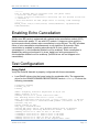
NOTE: Please focus on the switch number & connection number of switch SW6 shown in
the below diagram.
WWW.ALLO.COM
Page 2
BRI Card User Manual – Version 1.0
ALLO_4 Port BRI card Jumper Setting:
Power feeding Only for NT Mode)
Pullup/Pull down for TE/NT(SW6)
1
2
3
4
1
2
3
4
Switch in ON Position:
TE Mode
Switch in Off Position:
NT Mode
Without jumper:
TE Mode
SW6
Jumper Settings for
TE/NT Mode
J13-J16
Set all
jumpers to
the right
to select
NT Mode
for this
port.
PORT
4
Set all
jumpers to
the left to
select TE
Mode for
this port.
PORT
2
SW4
+40V
1
2
3
4
T4
J9-J12 SW3
P2
+40V
T3
J5-J8
SW2
+40V
P3
T2
P6
+40V
LDO
J1-J4
PORT
1
P5
PCM IN
PCM OUT
PORT
3
With jumper:
NT Mode (connect the
jumpers as per the port
number identification on
top).
+40V
SW1
HFC-4S
P6 – to use
only for NT
mode
SMPS
POWER
T1
Osc
Termination of S/T Interface(100ohm)
(SW1,SW2,SW3,SW4)
+3.3V Power Selection
PCI +3.3V
Switch in ON Position:
MODE = NT
+5V to 3.3V
converter
Switch in OFF Position:
MODE = TE
Figure 1: Jumper & switch position for CB400P/E cards
WWW.ALLO.COM
Page 3
BRI Card User Manual – Version 1.0
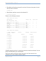
BRI_PCI_2 Port Jumper Setting:
Power feeding Only for NT Mode)
Pullup/Pull down for TE/NT(SW6)
1
2
1
2
With jumper:
NT Mode (connect the
jumpers as per the port
number identification on
top).
Switch in ON Position:
TE Mode
Switch in Off Position:
NT Mode
Without jumper:
TE Mode
SW6
Jumper Settings for
TE/NT Mode
P5
1
PCM IN
Set all
jumpers to
the right
to select
NT Mode
for this
port.
PCM OUT
J5-J8
SW2
PORT
2
Set all
jumpers to
the left to
select TE
Mode for
this port.
P2
+40V
P3
T2
P6
+40V
LDO
J1-J4
PORT
1
2
+40V
SW1
HFC-4S
P6 – to use
only for NT
mode
SMPS
POWER
T1
Osc
Termination of S/T Interface(100ohm)
(SW1,SW2)
+3.3V Power Selection
PCI +3.3V
Switch in ON Position:
MODE = NT
+5V to 3.3V
converter
Switch in OFF Position:
MODE = TE
Figure 2: Jumper & switch position for CB200P/E cards
WWW.ALLO.COM
Page 4
BRI Card User Manual – Version 1.0
NT or TE Mode Selection
NT and TE mode is determined by TE/NT Mode setting jumpers & switches, power
feeding jumpers and termination switch. Each of the four/two ports can be set for TE
or NT mode independently.
Note: The default Jumper setting is in TE mode
TE mode: Place the group of 4 TE/NT Mode setting jumpers on position 1-2 of the
connectors, termination switches towards OFF position, TE/NT Mode setting switch
SW6 towards ON position and remove the power feeding jumpers.
NT mode: Place the group of 4 TE/NT Mode setting jumpers on position 2-3 of the
connectors, termination switches towards ON position, TE/NT Mode setting switch
SW6 towards OFF position
Terminating the NT Mode Line
In NT mode, an additional 100 ohm termination can be provided for each port with
the termination DIP switches. See Figure 1 & 2, for a detailed illustration of this
setting. This switch must not be turned OFF in TE mode. The default setting is OFF.
Onboard Power for NT Mode
ISDN phones can be externally powered or powered from the BRI line. While using
phones, sourcing power from BRI lines, following settings are necessary.
SMPS power should be connected on P6. Power feeding jumpers should be
connected for each port. See Figure 1 & 2 for a detailed illustration of this setting.
These jumpers must be removed in TE mode. The default setting is jumpers are
open.
Software Installation
Allo.com Digital cards hardware are only supported under Linux. It requires drivers
and libraries which are not integrated with the Linux kernel.
Recommendation
Linux distributions: CentOS 5.4/5.5 and Ubuntu 10.04/11.10
Asterisk Version: Asterisk 1.4/1.6/1.8
Allo Dahdi Driver: Dahdi 2.4.x/2.5/2.6.x/2.7.X
For an introduction to Asterisk, including additional information on its configuration,
setups, and features, please refer to: http://www.asterisk.org
To install your CB400P/CB400E/CB200P/CB200E card, you will need:
•
•
•
Full Linux kernel 2.6.15 (or later) source code.
Development libraries and headers for ncurses
Development libraries and headers for zlib and openssl
WWW.ALLO.COM
Page 5
BRI Card User Manual – Version 1.0
•
•
Development libraries and headers for newt
GCC and standard software build tools
It is recommended that you use the most recent version of the Asterisk, DAHDI, and
libpri software with the patches provided for the best results. Asterisk 1.4 releases
later than 1.4.21, and all releases of Asterisk 1.6, will automatically use DAHDI. If
you wish to use the old versions of asterisk 1.4 or 1.2, you will need to follow the
installation procedure with mISDN and mISDNuser.
Using Dahdi
Installation Test Environment considered:
OS
Kernel version
Asterisk version
Allo Dahdi version
Libpri version
Hardware
:
:
:
:
:
:
CentOS 5.5
2.6.18-274.7.1.el5
Asterisk-1.8.4.2
dahdi-linux-complete-2.5.0.1+2.5.0.1 from
libpri-1.4
CB400P/CB400E/ CB200P/CB200E
1. After inserting the card into your PCI slot, boot your machine to linux and execute
the following command to list the devices detected by the PCI bus:
# lspci -vn
Confirm the output lists a device with Allo.com’s PCI vendor ID which is “b51a”.
The output will be similar to the following:
00:09.0 ISDN controller: Cologne Chip Designs GmbH ISDN network
Controller [HFC-4S] (rev 01)
Subsystem: Cologne Chip Designs GmbH Unknown device b51a
Note: The output of lspci may or may not state “Allo.com”. If it does not, this does
not indicate a problem and the device ID may change due to chip upgrade.
The Allo.com card identifier should be listed. If a card identifier is not listed, then
your machine is not PCI 2.2 (or higher), and the card will not work.
2. To install Libpri, DAHDI and Asterisk in CentOS, we have to install the following
prerequisite packages:
bison bison-devel zlib zlib-devel openssl openssl-devel gnutls-devel flex gcc gccc++
Execute the following command to install the above mentioned packages:
# yum install bison bison-devel zlib zlib-devel openssl openssl-devel
gnutls-devel flex gcc gcc-c++ libxml2
3. Download the libpri software, which are available at
http://downloads.asterisk.org/pub/telephony/libpri/libpri-1.4-current.tar.gz
# wget http://downloads.asterisk.org/pub/telephony/libpri/libpri-1.4current.tar.gz
WWW.ALLO.COM
Page 6
BRI Card User Manual – Version 1.0
4. Expand the downloaded libpri under /usr/src/ directory, compile its contents, and
install the drivers.
#
#
#
#
tar -zxvf libpri-1.4-current.tar.gz
cd libpri-1.4
make
make install
5. Download the ALLO DAHDI drivers, which are available at
http://www.allo.com/isdn-bri-card.html under “DRIVERS & MANUAL “Section.
# wget http://www.allo.com/firmware/bri-card/allo-dahdi-drivers/dahdilinux-complete-2.5.0.1+2.5.0.1.tar.gz
6. Untar the downloaded file, compile and install using the following commands
#
#
#
#
#
#
cd /usr/src
tar -zxvf dahdi-linux-complete-2.5.0.1+2.5.0.1.tar.gz
cd dahdi-linux-complete-2.5.0.1+2.5.0.1
make
make install
make config
Note: Executing ‘make config’ will install an init script and symlinks which will
allow you to start and stop DAHDI as a service.
7. Asterisk installation
For using Asterisk for your application, follow the steps below.
Download the Asterisk 1.8 latest release version.
# wget http://downloads.digium.com/pub/telephony/asterisk/asterisk-1.8current.tar.gz
# tar –xzvf asterisk-1.8-current.tar.gz
# cd asterisk-1.8/
# ./configure --with-pri=../libpri-1.4 --with-dahdi=../dahdi-linuxcomplete-2.5.0.1+2.5.0.1
# make menuselect
# make
# make install
If this is the first Asterisk installation on this system, you should install the sample
configuration files. To do this, run:
# make samples
Note: Running this command will overwrite any older Asterisk configuration files
that you have in the /etc/asterisk directory.
WWW.ALLO.COM
Page 7
BRI Card User Manual – Version 1.0
Using mISDN
Installation Test Environment considered:
OS
Kernel version
Asterisk version
mISDN version
Hardware
:
:
:
:
:
CentOS 5.5
2.6.18-274.7.1.el5
Asterisk 1.4.18
mISDN v1_1_9.1
CB400P/CB400E/ CB200P/CB200E
1. After inserting the card into your PCI slot, boot your machine to linux and execute
the following command to list the devices detected by the PCI bus
# lspci -vn
Confirm the output lists a device with Allo.com’s PCI vendor ID which is “b51a”.
The output will be similar to the following:
00:09.0 ISDN controller: Cologne Chip Designs GmbH ISDN network
Controller [HFC-4S] (rev 01)
Subsystem: Cologne Chip Designs GmbH Unknown device b51a
Note: The output of lspci may or may not state “Unknown device”. If it does not,
this does not indicate a problem.
The Allo.com card identifier should be listed. If a card identifier is not listed, then
your machine is not PCI 2.2 (or higher), and the card will not work.
2. To install asterisk and mISDN in centos OS, we have to install the following
prerequisite packages
bison bison-devel zlib zlib-devel openssl openssl-devel gnutls-devel flex gcc gccc++
Execute the following command to install the above mentioned packages:
# yum install bison bison-devel zlib zlib-devel openssl openssl-devel
gnutls-devel flex gcc gcc-c++
3. Download the mISDN and mISDNuser driver, which are available at:
http://www.allo.com/isdn-bri-card.html
#wget http://www.allo.com/firmware/bri-card/mISDN.tgz
#wget http://www.allo.com/firmware/bri-card/mISDNuser-1_1_9.tar.gz
4. Expand the downloaded file, compile its contents, and install the drivers and
tools.
#
#
#
#
tar -xvzf mISDN.tar.gz
cd mISDN-1_1_9.1/
make
make install
WWW.ALLO.COM
Page 8
BRI Card User Manual – Version 1.0
#
#
#
#
tar -xvzf mISDNuser.tar.gz
cd mISDNuser-1_1_9.1/
make
make install
5. Asterisk Installation
For using Asterisk for your application, follow the steps below.
• Download the Asterisk version 1.4.18
#wget
http://downloads.asterisk.org/pub/telephony/asterisk/releases/asterisk1.4.18.tar.gz
•
#
#
#
#
#
#
Expand the downloaded file, compile and install.
tar -zxvf asterisk-X.X-current.tar.gz
cd asterisk-X.X.X/
./configure
make menuselect
make
make install
If this is the first Asterisk installation on this system, you should install the sample
configuration files. To do this, run:
# make samples
Note: Running this command will overwrite any older Asterisk configuration files
that you have in the /etc/asterisk directory.
Software Configuration
This session will provide steps for configuring the card and verifying its setup.
Using Dahdi
After compiling & installing DAHDI and Asterisk, please add the line "allo4xxp" at the
end of the file in /etc/dahdi/modules and start load the driver by running:
•
Load the Dahdi drivers
# /etc/init.d/dahdi start
Loading DAHDI hardware modules:
wct4xxp:
wcte12xp:
wct1xxp:
wcte11xp:
wctdm24xxp:
wcfxo:
wctdm:
wcb4xxp:
WWW.ALLO.COM
[
[
[
[
[
[
[
[
OK
OK
OK
OK
OK
OK
OK
OK
]
]
]
]
]
]
]
]
Page 9
BRI Card User Manual – Version 1.0
wctc4xxp:
xpp_usb:
[
[
allo4xxp:
]
]
[ OK ]
Running dahdi_cfg:
•
OK
OK
[
OK
]
Generate config files
# dahdi_genconf
This will generate /etc/dahdi/system.conf and etc/asterisk/dahdi-channels.conf
files automatically. Checking whether the generated files information agrees with
your hardware setup, if not, you should modify to your specific requirements. Do
not forget to confirm dahdi-channels.conf is included in chan_dahdi.conf, if not
included, run command:
# echo "#include dahdi-channels.conf" >> /etc/asterisk/chan_dahdi.conf
•
Reload parameters in driver
# dahdi_cfg -vvvvv
The command is used for reading and loading parameters in the configuration file
system.conf and writing to the hardware. A part of the output is showed below.
# dahdi_cfg
-vvvvv
DAHDI Tools Version - 2.5.0.1
DAHDI Version: 2.5.0.1
Echo Canceller(s): HWEC
Configuration
======================
SPAN
SPAN
SPAN
SPAN
1:
2:
3:
4:
CCS/
CCS/
CCS/
CCS/
AMI
AMI
AMI
AMI
Build-out:
Build-out:
Build-out:
Build-out:
0
0
0
0
db
db
db
db
(CSU)/0-133
(CSU)/0-133
(CSU)/0-133
(CSU)/0-133
feet
feet
feet
feet
(DSX-1)
(DSX-1)
(DSX-1)
(DSX-1)
Channel map:
Channel 01: Clear channel (Default) (Echo Canceler: none) (Slaves: 01)
Channel 02: Clear channel (Default) (Echo Canceler: none) (Slaves: 02)
Channel 03: Hardware assisted D-channel (Default) (Echo Canceler: none)
(Slaves: 03)
Channel 04: Clear channel (Default) (Echo Canceler: none) (Slaves: 04)
Channel 05: Clear channel (Default) (Echo Canceler: none) (Slaves: 05)
Channel 06: Hardware assisted D-channel (Default) (Echo Canceler: none)
(Slaves: 06)
Channel 07: Clear channel (Default) (Echo Canceler: none) (Slaves: 07)
Channel 08: Clear channel (Default) (Echo Canceler: none) (Slaves: 08)
Channel 09: Hardware assisted D-channel (Default) (Echo Canceler: none)
(Slaves: 09)
Channel 10: Clear channel (Default) (Echo Canceler: none) (Slaves: 10)
WWW.ALLO.COM
Page 10
BRI Card User Manual – Version 1.0
Channel 11: Clear channel (Default) (Echo Canceler: none) (Slaves: 11)
Channel 12: Hardware assisted D-channel (Default) (Echo Canceler: none)
(Slaves: 12)
12 channels to configure.
Setting
Setting
Setting
Setting
Setting
Setting
Setting
Setting
Setting
Setting
Setting
Setting
echocan
echocan
echocan
echocan
echocan
echocan
echocan
echocan
echocan
echocan
echocan
echocan
for
for
for
for
for
for
for
for
for
for
for
for
channel
channel
channel
channel
channel
channel
channel
channel
channel
channel
channel
channel
1 to none
2 to none
3 to none
4 to none
5 to none
6 to none
7 to none
8 to none
9 to none
10 to none
11 to none
12 to none
The following is a typical system.conf setup for BRI:
# Span 1: B4/0/1 "B4XXP (PCI) Card 0 Span 1" (MASTER) AMI/CCS
span=1,1,0,ccs,ami
# termtype: te
bchan=1-2
hardhdlc=3
# Span 2: B4/0/2 "B4XXP (PCI) Card 0 Span 2" AMI/CCS
span=2,2,0,ccs,ami
# termtype: te
bchan=4-5
hardhdlc=6
# Span 3: B4/0/3 "B4XXP (PCI) Card 0 Span 3" AMI/CCS RED
span=3,3,0,ccs,ami
# termtype: te
bchan=7-8
hardhdlc=9
# Span 4: B4/0/4 "B4XXP (PCI) Card 0 Span 4" AMI/CCS RED
span=4,4,0,ccs,ami
# termtype: te
bchan=10-11
hardhdlc=12
# Global data
loadzone
defaultzone
= us
= us
Using mISDN
•
Modify the /etc/modprobe.d/blacklist file to add some blacklist. Add the following
lines in the end of file.
blacklist
blacklist
blacklist
blacklist
blacklist
hisax
hisax_fcpcipnp
hisax_isac
crc_ccitt
isdn
WWW.ALLO.COM
Page 11
BRI Card User Manual – Version 1.0
blacklist
blacklist
blacklist
blacklist
blacklist
blacklist
blacklist
•
slhc
capi
capifs
kernelcapi
kernel_capi
avmfritz
hfc4s8s_l1
Execute the following command to confirm the card is detected using the mISDN
tool.
# mISDN scan
1 mISDN compatible device(s) found:
>> BN4S0
•
Execute the following command to generate the configure file /etc/mISDN.conf.
And edit the file appropriately (it is self documented).
# mISDN config
Writing /etc/mISDN.conf for 1 mISDN compatible device(s):
>> BN4S0
/etc/mISDN.conf already present, saving a backup: /etc/mISDN.conf.bak
•
Execute the following command to start the required mISDN drivers.
# mISDN start
-- Loading mISDN modules ->> /sbin/modprobe --ignore-install capi
>> /sbin/modprobe --ignore-install mISDN_core debug=0
>> /sbin/modprobe --ignore-install mISDN_l1 debug=0
>> /sbin/modprobe --ignore-install mISDN_l2 debug=0
>> /sbin/modprobe --ignore-install l3udss1 debug=0
>> /sbin/modprobe --ignore-install mISDN_capi
>> /sbin/modprobe --ignore-install hfcmulti type=0x4
protocol=0x2,0x2,0x2,0x2 layermask=0xf,0xf,0xf,0xf poll=128 debug=0
timer=0
>> /sbin/modprobe --ignore-install mISDN_dsp debug=0 options=0
•
Execute the following command to check the port configurations.
# misdnportinfo
Port 1: TE-mode BRI S/T interface
-> Protocol: DSS1 (Euro ISDN)
-> Layer 4 protocol 0x04000001 is
-> childcnt: 2
* Port NOT useable for PBX (maybe
-------Port 2: TE-mode BRI S/T interface
-> Protocol: DSS1 (Euro ISDN)
-> Layer 4 protocol 0x04000001 is
-> childcnt: 2
* Port NOT useable for PBX (maybe
-------Port 3: TE-mode BRI S/T interface
-> Protocol: DSS1 (Euro ISDN)
-> Layer 4 protocol 0x04000001 is
-> childcnt: 2
* Port NOT useable for PBX (maybe
WWW.ALLO.COM
line (for phone lines)
detected, but not allowed for TE lib.
there is already a PBX running?)
line (for phone lines)
detected, but not allowed for TE lib.
there is already a PBX running?)
line (for phone lines)
detected, but not allowed for TE lib.
there is already a PBX running?)
Page 12
BRI Card User Manual – Version 1.0
-------Port 4: TE-mode BRI S/T interface
-> Protocol: DSS1 (Euro ISDN)
-> Layer 4 protocol 0x04000001 is
-> childcnt: 2
* Port NOT useable for PBX (maybe
-------mISDN_close: fid(3) isize(131072)
iend(0x8410060)
line (for phone lines)
detected, but not allowed for TE lib.
there is already a PBX running?)
inbuf(0x8410060) irp(0x8410060)
Enabling Echo Cancellation
All Allo.com BRI cards is enhanced with optional echo cancellation module (LEC).
Model names with postfix “D” are with LEC module. It improves voice quality in
environments where software echo cancellation is not sufficient. The LEC provides
64ms of echo cancellation simultaneously on all eight/four B-channels. Echo
cancellation is enabled by setting echocancel=64 in chan_dahdi.conf and
vpmsupport=1 in /etc/modprobe.d/dahdi.conf for wcb4xxp. Echo cancellation is
disabled by setting echocancel=0 in chan_dahdi.conf and vpmsupport=0 in
/etc/modprobe.d/dahdi.conf for wcb4xxp. (mISDN driver will not support echo
cancellation).
Test Configuration
Using Dahdi
Verify the Dahdi & Asterisk is properly configured with these commands.
•
Load DAHDI drivers into the kernel using the modprobe utility. The appropriate
driver for the CB400P/CB400E/CB200P/CB200E cards is cem4xxp. Execute the
following commands:
# modprobe cem4xxp
# dahdi_cfg -vv
# dmesg
dahdi: Telephony Interface Registered on major 196
dahdi: Version: 2.5.0.1
wcb4xxp 0000:00:0c.0: probe called for b4xx...
PCI: Enabling device 0000:00:0c.0 (0100 -> 0103)
ACPI: PCI Interrupt 0000:00:0c.0[A] -> GSI 17 (level, low) -> IRQ 201
*cem4xxp* 0000:00:0c.0: Identified CEM QuadBri (controller rev 1) at
0001e800, IRQ 201
Inside zarlink_ec_init
Chip Type: zl50234/zl50235
zarlink_LEC_chip: Select chip ZL38065/ZL50232 with 32 channels
zarlink_LEC_chip: Inserting EchoCanceler module. 32 channels
cem4xxp 0000:00:0c.0: GPIO e0 Port 1: TE mode
**cem4xxp** 0000:00:0c.0: GPIO e0 Port 2: NT mode
**cem4xxp** 0000:00:0c.0: GPIO e0 Port 3: NT mode
cem4xxp 0000:00:0c.0: GPIO e0 Port 4: NT mode
cem4xxp 0000:00:0c.0: Did not do the highestorder stuff
WWW.ALLO.COM
Page 13
BRI Card User Manual – Version 1.0
•
Run dahdi_tool from the command line and see if the span turns green for each
span you have connected.
# dahdi_tool
•
Start Asterisk, and then connect to the Asterisk CLI
# asterisk -vvvvvgc
Please run the following command:
*CLI> dahdi show status
Description
Fra Codi Options
B4XXP (PCI)
CCS AMI
B4XXP (PCI)
CCS AMI
B4XXP (PCI)
CCS AMI
B4XXP (PCI)
CCS AMI
Alarms
IRQ
bpviol CRC
0
0
0
0
0
0
0
0
0
0
0
0
LBO
Card 0 Span 1
0 db (CSU)/0-133
Card 0 Span 2
0 db (CSU)/0-133
Card 0 Span 3
0 db (CSU)/0-133
Card 0 Span 4
0 db (CSU)/0-133
OK
feet (DSX-1)
OK
feet (DSX-1)
RED
feet (DSX-1)
RED
feet (DSX-1)
*CLI> dahdi show channels
Chan
Blocked
Extension
State
pseudo
In Service
1
In Service
2
In Service
4
In Service
5
In Service
7
In Service
8
In Service
10
In Service
11
In Service
Context
Language
default
MOH Interpret
default
from-pstn
default
from-pstn
default
from-pstn
default
from-pstn
default
from-pstn
default
from-pstn
default
from-pstn
default
from-pstn
default
If DAHDI channels are found, it means they have been loaded into Asterisk. You are
going to edit dial plan by your requirements.
Users must make sure that the context "from-pstn" and "from-internal" are in
extensions.conf, here a simple example is given:
WWW.ALLO.COM
Page 14
BRI Card User Manual – Version 1.0
[from-pstn]
exten => _X.,1,Dial(dahdi/1)
exten => _X.,n,Hangup()
[from-intern]
exten => 100,1,Dial(dahdi/4/${EXTEN})
exten => 100,n,Hangup()
The dial plan achieves that, when an extension telephone dials 100, Asterisk will
transfer through channel 4 to the destination. While a call comes from PSTN line,
Asterisk answers firstly, and then gets through to the extension set which connects
channel 1.
After saving your dial plan, please run "asterisk –r", then execute "reload" in the CLI.
Next you are able to make calls.
Using mISDN
In the following procedures, loop back test performed to confirm the correct
installation of the card. For this a straight-through cable is used.
•
Configure the port 1 as NT mode and port 4 as TE mode by modifying the
/etc/mISDN.conf file.
<?xml version="1.0"?>
<!-- - - - - - - - - - - - - - - - - - - - - - - - - - - - - - - - - - - - - - Card Type: BN2S0, BN4S0, BN8S0
Card Attributes: ulaw=(yes|no), dtmf=(yes|no), pcm_slave=(yes|no),
ignore_pcm_frameclock=(yes|no), rxclock=(yes|no),
crystalclock=(yes|no), watchdog=(yes|no)
Port Attributes: mode=(te|nt), link=(ptp|ptmp), master-clock=(yes|no),
capi=(yes|no)
- - - - - - - - - - - - - - - - - - - - - - - - - - - - - - - - - - - - - - Card Type: BN2E1
Card Attributes: ulaw=(yes|no), dtmf=(yes|no), pcm_slave=(yes|no),
ignore_pcm_frameclock=(yes|no), rxclock=(yes|no),
crystalclock=(yes|no), watchdog=(yes|no)
Port Attributes: mode=(te|nt), link=(ptp|ptmp), optical=(yes|no),
los=(yes|no),
ais=(yes|no), slip=(yes|no), nocrc4=(yes|no), capi=(yes|no)
- - - - - - - - - - - - - - - - - - - - - - - - - - - - - - - - - - - - - - Card Type: hfcmulti, avmfritz, w6692pci
Port Attributes: mode=(te|nt), link=(ptp|ptmp), capi=(yes|no)
- - - - - - - - - - - - - - - - - - - - - - - - - - - - - - - - - - - - - - Module: hfcmulti
Options: poll=<number>, pcm=<number>, debug=<number>, timer=(yes|no)
- - - - - - - - - - - - - - - - - - - - - - - - - - - - - - - - - - - - - - Module: hfcsusb
Options: debug=<number> poll=<number>
WWW.ALLO.COM
Page 15
BRI Card User Manual – Version 1.0
- - - - - - - - - - - - - - - - - - - - - - - - - - - - - - - - - - - - - - Module: xhfc
Options: debug=<number>
Port Attributes: mode=(te|nt), link=(ptp|ptmp), line=(s0|up)
capi=(yes|no) lineloop_b1=(yes|no) lineloop_b2=(yes|no),
lineloop_d=(yes|no)
polx=(yes|no)
- - - - - - - - - - - - - - - - - - - - - - - - - - - - - - - - - - - - - - Module: mISDN_dsp
Options: debug=<number>, options=<number>, poll=<number>,
dtmfthreshold=<number>
- - - - - - - - - - - - - - - - - - - - - - - - - - - - - - - - - - - - - - -->
<mISDNconf>
<module poll="128" debug="0" timer="no">hfcmulti</module>
<module debug="0" options="0">mISDN_dsp</module>
<devnode user="root" group="root" mode="644">mISDN</devnode>
<card type="BN4S0">
<port mode="te" link="ptmp">1</port>
<port mode="te" link="ptmp">2</port>
<port mode="te" link="ptmp">3</port>
<port mode="nt" link="ptmp">4</port>
</card>
</mISDNconf>
Restart the mISDN drivers by executing the command
# mISDN restart
•
•
Plug the straight-through cable into the port 1 and port 4.
Modify the Asterisk config files appropriately.
#vi /etc/asterisk/misdn.conf
[outcall]
ports=1
context=from-isdn
[isdn]
ports=2,3,4
context=to-isdn
; adding the postfix 'ptp' to a port number is obsolete now, chan_misdn
; parses /etc/misdn-init.conf and sets the ptp mode to the corresponding
; configs. For backwards compatibility you can still set ptp here.
Edit dial-plan in extensions.conf file
#vi /etc/asterisk/extensions.conf
[from-isdn]
exten => _X., 1, Dial(SIP/555)
[to-isdn]
exten => _X., 1, Dial(mISDN/g:isdn/${EXTEN})
The dial plan is linked with misdn.conf. The example shows the port 1 is used for
inbound calls and port 2, 3 & 4 are used for outbound calls.
After asterisk reload, check the status of misdn module through the CLI.
WWW.ALLO.COM
Page 16
BRI Card User Manual – Version 1.0
*CLI> misdn show stacks
BEGIN STACK_LIST:
* Port 1 Type TE Prot. PMP
* Port 2 Type NT Prot. PMP
* Port 3 Type NT Prot. PMP
* Port 4 Type NT Prot. PMP
•
L2Link
L2Link
L2Link
L2Link
DOWN
DOWN
DOWN
DOWN
L1Link:UP Blocked:0 Debug:0
L1Link:DOWN Blocked:0 Debug:0
L1Link:DOWN Blocked:0 Debug:0
L1Link:UP Blocked:0 Debug:0
The below screens show the asterisk debug capture of outbound call & inbound
call.
Inbound call
*CLI> -- Executing [08067120954@from-isdn:1] Dial("mISDN/1-u0",
"mISDN/4/08067120954") in new stack
-- Called 4/08067120954
-- mISDN/tmp2-u1 is proceeding passing it to mISDN/1-u0
-- mISDN/tmp2-u1 is ringing
== Spawn extension (isdn-in, 08067120954, 1) exited non-zero on
'mISDN/1-u0'
Outbound call
*CLI> -- Executing [7259691221@to-isdn:1] Dial("mISDN/7-u0",
"mISDN/1/7259691221") in new stack
-- Called 1/7259691221
-- mISDN/1-u2 is proceeding passing it to mISDN/7-u0
-- mISDN/1-u2 is ringing
-- mISDN/1-u2 is making progress passing it to mISDN/7-u0
== Spawn extension (isdn-out, 7259691221, 1) exited non-zero on
'mISDN/7-u0'
P[ 0] received 1k Unhandled Bchannel Messages: prim f2481 len 0 from
addr 55010480, dinfo 0 on this port.
Reference
http://allo.com
http://www.misdn.org/index.php/Main_Page
http://www.asterisk.org
http://www.voip-info.org
WWW.ALLO.COM
Page 17