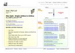
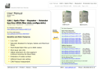
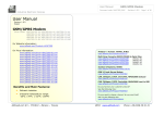
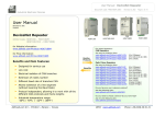
1
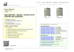
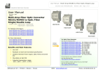
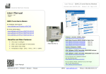
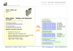
User Manual
RS232/RS485/CAN/LAN / Optical Fibres
Document code: MN67701_ENG
Revision 1.002
Page 1 of 47
Industrial Electronic Devices
User Manual
Revision 1.002
English
Copper / Optical Fiber - Converter
( Order Code: HD67701 - HD67702 )
for Website information:
www.adfweb.com?Product=HD67702-2
www.adfweb.com?Product=HD67702-4
www.adfweb.com?Product=HD67702-C
www.adfweb.com?Product=HD67702-E
for Price information:
www.adfweb.com?Price=HD67702-2-0-H5S-H5S
HD67033M
www.adfweb.com?Price=HD67702-4-0-H5S-H5S
www.adfweb.com?Price=HD67702-C-0-H5S-H5S
www.adfweb.com?Price=HD67702-E-0-H5S-H5S
www.adfweb.com?Price=HD67702-2-0-D5M-D5M
www.adfweb.com?Price=HD67702-4-0-D5M-D5M
www.adfweb.com?Price=HD67702-C-0-D5M-D5M
www.adfweb.com?Price=HD67702-E-0-D5M-D5M
Benefits and Main Features:
Resistant to harsh environmental specifications
Electrical isolation
Temperature range: -40°C / 85°C (-40°F / 185°F)
HD67702
For Optic Fibres Repeaters
See also the following links:
www.adfweb.com?Product=HD67117F (For CANopen and CAN 2.0A)
www.adfweb.com?Product=HD67117FSX (For CANopen and CAN 2.0A)
www.adfweb.com?Product=HD67180F (For DeviceNET)
www.adfweb.com?Product=HD67180FSX (For DeviceNET)
www.adfweb.com?Product=HD67181F (For CAN 2.0B)
www.adfweb.com?Product=HD67181FSX (For CAN 2.0B)
www.adfweb.com?Product=HD67182F (For J1939)
www.adfweb.com?Product=HD67182FSX (For J1939)
www.adfweb.com?Product=HD67221F (Copper Bridge)
www.adfweb.com?Product=HD67221FSX (Copper Bridge)
www.adfweb.com?Product=HD67238F (For RS232/RS485)
Do you have an your customer protocol?
See the following links:
www.adfweb.com?Product=HD67003
Do you need to choose a device? do you want help?
User Manual
ADFweb.com Srl – IT31010 – Mareno – Treviso
Ask it to the following link:
www.adfweb.com?Cmd=helpme
INFO: www.adfweb.com
Phone +39.0438.30.91.31
User Manual
RS232/RS485/CAN/LAN / Optical Fibres
Document code: MN67701_ENG
Revision 1.002
Page 2 of 47
Industrial Electronic Devices
INDEX:
INDEX
UPDATED DOCUMENTATION
REVISION LIST
WARNING
TRADEMARKS
SECURITY ALERT
EXAMPLES
CONNECTION SCHEME
CHARACTERISTICS
CONFIGURATION
POWER SUPPLY
FUNCTION MODES
LEDS
RS232
RS485
CAN
ETHERNET
USB
OPTICAL FIBER
I/O MODULE
USE OF COMPOSITOR SW67701
NEW/OPEN PROJECT
SOFTWARE OPTIONS
CONFIGURE DEVICES
MODBUS REGISTERS TABLE
UPDATE BY USB
UPDATE BY ETHERNET
MECHANICAL DIMENSIONS
ORDER CODE
ACCESSORIES
DISCLAIMER
OTHER REGULATIONS AND STANDARDS
WARRANTIES AND TECHNICAL SUPPORT
PRODUCTS AND RELATED DOCUMENTS
Page
2
2
2
2
2
3
4
6
15
15
16
17
18
19
20
21
22
22
23
24
30
31
32
33
36
38
39
41
42
45
46
46
47
47
UPDATED DOCUMENTATION:
Dear customer, we thank you for your attention and we remind you that
you need to check that the following document is:
Updated
Related to the product you own
To obtain the most recently updated document, note the “document code”
that appears at the top right-hand corner of each page of this document.
With this “Document Code” go to web page www.adfweb.com/download/
and search for the corresponding code on the page. Click on the proper
“Document Code” and download the updates.
REVISION LIST:
Revision
Date
Author Chapter
1.000
01/03/2013
Ff
All
1.001
17/02/2014
Ff
All
1.002
15/04/2015
Ff
All
Description
First Released Version
Revision
Added new features
WARNING:
ADFweb.com reserves the right to change information in this manual about
our product without warning.
ADFweb.com is not responsible for any error this manual may contain.
TRADEMARKS:
All trademarks mentioned in this document belong to their respective
owners.
Pagina 2 di 47
Pagina 247
ADFweb.com Srl – IT31010 – Mareno – Treviso
INFO: www.adfweb.com
Phone +39.0438.30.91.31
User Manual
RS232/RS485/CAN/LAN / Optical Fibres
Document code: MN67701_ENG
Revision 1.002
Page 3 of 47
Industrial Electronic Devices
SECURITY ALERT:
GENERAL INFORMATION
To ensure safe operation, the device must be operated according to the instructions in the manual. When using the device, legal and
safety regulation are required for each individual application. The same applies also when using accessories.
INTENDED USE
Machines and systems must be designed so the faulty conditions do not lead to a dangerous situation for the operator (i.e.
independent limit switches, mechanical interlocks, etc.).
QUALIFIED PERSONNEL
The device can be used only by qualified personnel, strictly in accordance with the specifications.
Qualified personnel are persons who are familiar with the installation, assembly, commissioning and operation of this equipment and
who have appropriate qualifications for their job.
RESIDUAL RISKS
The device is state-of-the-art and is safe. The instruments can represent a potential hazard if they are inappropriately installed and
operated by untrained personnel. These instructions refer to residual risks with the following symbol:
This symbol indicates that non-observance of the safety instructions is a danger for people that could lead to serious injury or
death and / or the possibility of damage.
CE CONFORMITY
The declaration is made by our company. You can send an email to [email protected] or give us a call if you need it.
ADFweb.com Srl – IT31010 – Mareno – Treviso
INFO: www.adfweb.com
Phone +39.0438.30.91.31
User Manual
RS232/RS485/CAN/LAN / Optical Fibres
Document code: MN67701_ENG
Revision 1.002
Page 4 of 47
Industrial Electronic Devices
EXAMPLE OF CONNECTION:
ADFweb.com Srl – IT31010 – Mareno – Treviso
INFO: www.adfweb.com
Phone +39.0438.30.91.31
User Manual
RS232/RS485/CAN/LAN / Optical Fibres
Document code: MN67701_ENG
Revision 1.002
Page 5 of 47
Industrial Electronic Devices
ADFweb.com Srl – IT31010 – Mareno – Treviso
INFO: www.adfweb.com
Phone +39.0438.30.91.31
User Manual
RS232/RS485/CAN/LAN / Optical Fibres
Document code: MN67701_ENG
Revision 1.002
Page 6 of 47
Industrial Electronic Devices
CONNECTION SCHEME:
Figure 1a: Connection Scheme for HD67701-2-0-xxx
ADFweb.com Srl – IT31010 – Mareno – Treviso
INFO: www.adfweb.com
Phone +39.0438.30.91.31
User Manual
RS232/RS485/CAN/LAN / Optical Fibres
Document code: MN67701_ENG
Revision 1.002
Page 7 of 47
Industrial Electronic Devices
Figure 1b: Connection Scheme for HD67702-2-0-xxx-xxx
ADFweb.com Srl – IT31010 – Mareno – Treviso
INFO: www.adfweb.com
Phone +39.0438.30.91.31
User Manual
RS232/RS485/CAN/LAN / Optical Fibres
Document code: MN67701_ENG
Revision 1.002
Page 8 of 47
Industrial Electronic Devices
Figure 1c: Connection Scheme for HD67701-4-0-xxx
ADFweb.com Srl – IT31010 – Mareno – Treviso
INFO: www.adfweb.com
Phone +39.0438.30.91.31
User Manual
RS232/RS485/CAN/LAN / Optical Fibres
Document code: MN67701_ENG
Revision 1.002
Page 9 of 47
Industrial Electronic Devices
Figure 1d: Connection Scheme for HD67702-4-0-xxx-xxx
ADFweb.com Srl – IT31010 – Mareno – Treviso
INFO: www.adfweb.com
Phone +39.0438.30.91.31
User Manual
RS232/RS485/CAN/LAN / Optical Fibres
Document code: MN67701_ENG
Revision 1.002
Page 10 of 47
Industrial Electronic Devices
Figure 1e: Connection Scheme for HD67701-C-0-xxx
ADFweb.com Srl – IT31010 – Mareno – Treviso
INFO: www.adfweb.com
Phone +39.0438.30.91.31
User Manual
RS232/RS485/CAN/LAN / Optical Fibres
Document code: MN67701_ENG
Revision 1.002
Page 11 of 47
Industrial Electronic Devices
Figure 1f: Connection Scheme for HD67702-C-0-xxx-xxx
ADFweb.com Srl – IT31010 – Mareno – Treviso
INFO: www.adfweb.com
Phone +39.0438.30.91.31
User Manual
RS232/RS485/CAN/LAN / Optical Fibres
Document code: MN67701_ENG
Revision 1.002
Page 12 of 47
Industrial Electronic Devices
Figure 1g: Connection Scheme for HD67701-E-0-xxx
ADFweb.com Srl – IT31010 – Mareno – Treviso
INFO: www.adfweb.com
Phone +39.0438.30.91.31
User Manual
RS232/RS485/CAN/LAN / Optical Fibres
Document code: MN67701_ENG
Revision 1.002
Page 13 of 47
Industrial Electronic Devices
Figure 1h: Connection Scheme for HD67702-E-0-xxx-xxx
ADFweb.com Srl – IT31010 – Mareno – Treviso
INFO: www.adfweb.com
Phone +39.0438.30.91.31
User Manual
RS232/RS485/CAN/LAN / Optical Fibres
Document code: MN67701_ENG
Revision 1.002
Page 14 of 47
Industrial Electronic Devices
Figure 1i: Connection Scheme for I/O module
ADFweb.com Srl – IT31010 – Mareno – Treviso
INFO: www.adfweb.com
Phone +39.0438.30.91.31
User Manual
RS232/RS485/CAN/LAN / Optical Fibres
Document code: MN67701_ENG
Revision 1.002
Page 15 of 47
Industrial Electronic Devices
CHARACTERISTICS
The HD67701 and HD67702 are a Copper / Optical Fiber Converters.
It has the following characteristics:
Triple isolation between Bus (copper) - Power Supply, Bus (copper) – Optical Fiber, Power Supply – Optical Fiber.;
Mountable on 35mm Rail DIN;
Two-directional information between Bus (copper) and Optical Fiber;
Wide power supply input range: 8…24V AC or 12…35V DC;
Wide temperature range: -40°C / 85°C [-40°F / +185°F].
CONFIGURATION:
You need Compositor SW67701 software on your PC in order to perform the following:
Define the parameters of RS232/RS485/CAN/Ethernet line;
Define the I/O map (if I/O module is present);
Update the device.
ADFweb.com Srl – IT31010 – Mareno – Treviso
INFO: www.adfweb.com
Phone +39.0438.30.91.31
User Manual
RS232/RS485/CAN/LAN / Optical Fibres
Document code: MN67701_ENG
Revision 1.002
Page 16 of 47
Industrial Electronic Devices
POWER SUPPLY:
The devices can be powered at 8…19V AC and 12…35V DC. For more details see the two tables below.
VAC
VDC
Vmin
Vmax
Vmin
Vmax
8V
24V
12V
35V
Consumption at 24V DC:
Device
Consumption [W/VA]
HD67701-2/4/C/E-0-xxx
3.5
HD67702-2/4/C/E-0-xxx-xxx
3.5
Caution: Not reverse the polarity power
HD67701
HD67702
ADFweb.com Srl – IT31010 – Mareno – Treviso
INFO: www.adfweb.com
Phone +39.0438.30.91.31
User Manual
RS232/RS485/CAN/LAN / Optical Fibres
Document code: MN67701_ENG
Revision 1.002
Page 17 of 47
Industrial Electronic Devices
FUNCTION MODES:
The device has got two functions mode depending of the position of the ‘Dip1 of Dip-Switch A’:
The first, with ‘Dip1 of Dip-Switch A’ at “OFF” position, is used for the normal working of the device.
The second, with ‘Dip1 of Dip-Switch A’ at “ON” position, is used for upload the Project and/or Firmware.
For the operations to follow for the updating, see ‘UPDATE DEVICE’ section.
According to the functioning mode, the LEDs will have specifics functions, see ‘LEDS’ section.
Warning:
Dip2 of ‘Dip-Switch A’ must be at ON position for working even if the Ethernet cable isn’t inserted.
ADFweb.com Srl – IT31010 – Mareno – Treviso
INFO: www.adfweb.com
Phone +39.0438.30.91.31
User Manual
RS232/RS485/CAN/LAN / Optical Fibres
Document code: MN67701_ENG
Revision 1.002
Page 18 of 47
Industrial Electronic Devices
LEDS:
The device has got five LEDs that are used to give information of the functioning status.
The various meanings of the LEDs are described in the table below.
LED
Normal Mode
Boot Mode
Blinks quickly: Boot state
1: Device State (green)
Blinks slowly (~1Hz)
2: Bus comm. (yellow)
Blinks quickly for a short time when a frame is
received (Serial, CAN or Ethernet)
Blinks quickly: Boot state
3: O.F.1 comm. (yellow)
Blinks quickly for a short time when data on Optical
Fiber 1 is received
Blinks quickly: Boot state
4: O.F.2 comm. (yellow)
Blinks quickly for a short time when data on Optical
Fiber 2 is received
Blinks very slowly (~0.5Hz): update in progress
ON: Ethernet cable inserted
Blinks quickly: Boot state
OFF: Ethernet cable not inserted
Blinks very slowly (~0.5Hz): update in progress
5: Ethernet Link (green)
(only for HD67701-E and
HD67702-E)
ADFweb.com Srl – IT31010 – Mareno – Treviso
Blinks very slowly (~0.5Hz): update in progress
Blinks very slowly (~0.5Hz): update in progress
Blinks very slowly (~0.5Hz): update in progress
Blinks quickly: Boot state
INFO: www.adfweb.com
Phone +39.0438.30.91.31
User Manual
RS232/RS485/CAN/LAN / Optical Fibres
Document code: MN67701_ENG
Revision 1.002
Page 19 of 47
Industrial Electronic Devices
RS232 (for HD67701-2-0-xxx and HD67702-2-0-xxx-xxx):
The connection from RS232 socket to a serial port must be made with a cable with these characteristics:
It is recommended that the cable not exceed 15 meters.
ADFweb.com Srl – IT31010 – Mareno – Treviso
INFO: www.adfweb.com
Phone +39.0438.30.91.31
User Manual
RS232/RS485/CAN/LAN / Optical Fibres
Document code: MN67701_ENG
Revision 1.002
Page 20 of 47
Industrial Electronic Devices
RS485 (for HD67701-4-0-xxx and HD67702-4-0-xxx-xxx):
For terminate the RS485 line with a 220Ω resistor it is necessary that the ‘Dip1’ of the Dip-Switch B is at ON position.
The maximum length of the cable should be 1200m (4000 feet).
Here some codes of cables:
Belden: p/n 8132 - 2x 28AWG stranded twisted pairs conductor + foil shield + braid shield;
Belden p/n 82842 - 2x 24AWG stranded twisted pairs conductor + foil shield + braid shield;
Tasker: p/n C521 - 1x 24AWG twisted pair conductor + foil shield + braid shield;
Tasker: p/n C522 - 2x 24AWG twisted pairs conductor + foil shield + braid shield.
ADFweb.com Srl – IT31010 – Mareno – Treviso
INFO: www.adfweb.com
Phone +39.0438.30.91.31
User Manual
RS232/RS485/CAN/LAN / Optical Fibres
Document code: MN67701_ENG
Revision 1.002
Page 21 of 47
Industrial Electronic Devices
CAN (for HD67701-C-0-xxx and HD67702-C-0-xxx-xxx):
To terminate the CAN line with a 120Ω resistor it is necessary that the ‘Dip1’ of the Dip-Switch B is at ON position.
Cable characteristics:
DC parameter:
Impedance
AC parameters:
Impedance
Delay
120 Ohm/m
5 ns/m
Length
Baud Rate [bps]
10 K
20 K
50 K
100 K
125 K
250 K
500 K
800 K
1000 K
Length MAX [m]
5000
2500
1000
650
500
250
100
50
25
ADFweb.com Srl – IT31010 – Mareno – Treviso
70
INFO: www.adfweb.com
Ohm/m
Phone +39.0438.30.91.31
User Manual
RS232/RS485/CAN/LAN / Optical Fibres
Document code: MN67701_ENG
Revision 1.002
Page 22 of 47
Industrial Electronic Devices
ETHERNET (for HD67701-E-0-xxx and HD67702-E-0-xxx-xxx):
The Ethernet connection must be made using Connector2 of HD67701-E-0-xxx anb HD67702-E-0-xxx-xxx with at least a Category 7E
cable. The maximum length of the cable should not exceed 100m. The cable has to conform to the T568 norms relative to connections in
cat.7 up to 100 Mbps. To connect the device to an Hub/Switch is recommended the use of a straight cable, to connect the device to a
PC/PLC/other is recommended the use of a cross cable.
USB (updating port)
The USB connector (Connector2) is a Type-MINI AB Female. So the cable must be a Type-MINI AB Male.
ADFweb.com Srl – IT31010 – Mareno – Treviso
INFO: www.adfweb.com
Phone +39.0438.30.91.31
User Manual
RS232/RS485/CAN/LAN / Optical Fibres
Document code: MN67701_ENG
Revision 1.002
Page 23 of 47
Industrial Electronic Devices
OPTICAL FIBER:
On optical fiber side, the SFPs (Small Factor Pluggable) are mounted: They are interchangeable modules through which you can choose the
type of optical fiber and the maximum distance that can be covered.
In relation to the order code, it is possible to have different SFPs module mounted:
Single-Mode Optical Fiber, LC connectors, Maximum distance of 10 km
Multi-Mode Optical Fiber, LC connectors, Maximum distance 275 m (with 62.5/125 µm fiber) or 550 m (with 50/125 µm fiber)
None
ADFweb.com Srl – IT31010 – Mareno – Treviso
INFO: www.adfweb.com
Phone +39.0438.30.91.31
User Manual
RS232/RS485/CAN/LAN / Optical Fibres
Document code: MN67701_ENG
Revision 1.002
Page 24 of 47
Industrial Electronic Devices
I/O MODULE:
In relation to the order code, it is possible to have an I/O module to transmit over Optical Fiber DI and DO and pilot over long distance I/O
devices.
Digital Inputs:
There are two different ways to pilot the DI inside the I/O module:
Common Power Supply;
Different Voltage for each DI.
ADFweb.com Srl – IT31010 – Mareno – Treviso
INFO: www.adfweb.com
Phone +39.0438.30.91.31
User Manual
RS232/RS485/CAN/LAN / Optical Fibres
Document code: MN67701_ENG
Revision 1.002
Page 25 of 47
Industrial Electronic Devices
Common Power Supply:
It is possible to feed the I/O Module with a single Power Supply. In this way, to pilot the DI, it enough to short the pins of the DIs’
connectors.
ADFweb.com Srl – IT31010 – Mareno – Treviso
INFO: www.adfweb.com
Phone +39.0438.30.91.31
User Manual
RS232/RS485/CAN/LAN / Optical Fibres
Document code: MN67701_ENG
Revision 1.002
Page 26 of 47
Industrial Electronic Devices
STATUS OF INPUT
STATUS OF OUTPUT
STATUS OF OUTPUT CONTACT
Open
Not activated
NO – C
Closed (short circuit)
Activated
NC - C
Warning: Maximum voltage applied on Power Supply: 24V DC
Warning: Minimum voltage applied on Power Supply: 12V DC
ADFweb.com Srl – IT31010 – Mareno – Treviso
INFO: www.adfweb.com
Phone +39.0438.30.91.31
User Manual
RS232/RS485/CAN/LAN / Optical Fibres
Document code: MN67701_ENG
Revision 1.002
Page 27 of 47
Industrial Electronic Devices
Different Power Supply for each DI:
It is possible to pilot the DI of the module using a specific voltage for each DI. In order to change the status of the DI, it is enough to apply
or not the +V on the pins 1/3/5/7 and fix pins 2/4/6/8 to 0V.
R
1/3/5/7
R
+V
L
0V
2/4/6/8
R
R
STATUS INPUT
STATUS OF OUTPUT
STATUS OF OUTPUT CONTACT
Opened (V+ not applied)
Not activated
NO – C
Closed (V+ applied)
Activated
NC - C
Warning: Maximum voltage applied +V: 24V DC
Warning: Minimum voltage applied +V: 6V DC
ADFweb.com Srl – IT31010 – Mareno – Treviso
INFO: www.adfweb.com
Phone +39.0438.30.91.31
User Manual
RS232/RS485/CAN/LAN / Optical Fibres
Document code: MN67701_ENG
Revision 1.002
Page 28 of 47
Industrial Electronic Devices
Digital Outputs:
The Digital Outputs of the I/O module have two different states in relation to the pin where you will connect:
NO: Normally Open -> When the Output is not activated, the contact is in this position, so the it is closed between C and NO;
NC: Normally Close -> When the Output is activated, the contact is in this position, so it is closed between C and NC.
Note:
The DOs are clean contacts, any voltage is supplied.
ADFweb.com Srl – IT31010 – Mareno – Treviso
INFO: www.adfweb.com
Phone +39.0438.30.91.31
User Manual
RS232/RS485/CAN/LAN / Optical Fibres
Document code: MN67701_ENG
Revision 1.002
Page 29 of 47
Industrial Electronic Devices
Leds:
The I/O module has got eight LEDs that are used to give information of the DI and DO status.
The various meanings of the LEDs are described in the table below.
LED
1: DI1 (green)
2: DI2. (green)
3: DI3 (green)
4: DI4 (green)
5: DO1 (green)
6: DO2. (green)
7: DO3 (green)
8: DO4 (green)
MEANING
ON: Opened
OFF: Closed
ON: Opened
OFF: Closed
ON: Opened
OFF: Closed
ON: Opened
OFF: Closed
ON: Activated (NC-C)
OFF: Not Activated (NO-C)
ON: Activated (NC-C)
OFF: Not Activated (NO-C)
ON: Activated (NC-C)
OFF: Not Activated (NO-C)
ON: Activated (NC-C)
OFF: Not Activated (NO-C)
ADFweb.com Srl – IT31010 – Mareno – Treviso
INFO: www.adfweb.com
Phone +39.0438.30.91.31
User Manual
RS232/RS485/CAN/LAN / Optical Fibres
Document code: MN67701_ENG
Revision 1.002
Page 30 of 47
Industrial Electronic Devices
USE OF COMPOSITOR SW67701:
To configure the Converter, use the available software that runs with Windows called SW67701. It is downloadable on the site
www.adfweb.com and its operation is described in this document. (This manual is referenced to the last version of the software present on
our web site). The software works with MSWindows (XP, Vista, Seven, 8; 32/64bit).
When launching the SW67701, the window below appears (Fig. 2).
Note:
It is necessary to have installed .Net Framework 4.
Figure 2: Main window for SW67701
ADFweb.com Srl – IT31010 – Mareno – Treviso
INFO: www.adfweb.com
Phone +39.0438.30.91.31
User Manual
RS232/RS485/CAN/LAN / Optical Fibres
Document code: MN67701_ENG
Revision 1.002
Page 31 of 47
Industrial Electronic Devices
NEW CONFIGURATION / OPEN CONFIGURATION:
The “New Configuration” button creates the folder which contains the entire device’s configuration.
A device’s configuration can also be imported or exported:
To clone the configurations of a Programmable “Copper / Optical Fiber - Converter”
in order to configure another device in the same manner, it is necessary to maintain
the folder and all its contents;
To clone a project in order to obtain a different version of the project, it is sufficient
to duplicate the project folder with another name and open the new folder with the
button “Open Configuration”.
ADFweb.com Srl – IT31010 – Mareno – Treviso
INFO: www.adfweb.com
Phone +39.0438.30.91.31
User Manual
RS232/RS485/CAN/LAN / Optical Fibres
Document code: MN67701_ENG
Revision 1.002
Page 32 of 47
Industrial Electronic Devices
SOFTWARE OPTIONS:
By pressing the “Settings” (
compositor.
) button there is the possibility to change the language of the software and check the updatings for the
In the section “Language” it is possible to change the language of the
software.
In the section “Connection Options”, it is possible to check if there are some
updatings of the software compositor in ADFweb.com website.
Checking the option “Check Software Update at Start of Program”, the
SW67701 check automatically if there are updatings when it is launched.
ADFweb.com Srl – IT31010 – Mareno – Treviso
INFO: www.adfweb.com
Phone +39.0438.30.91.31
User Manual
RS232/RS485/CAN/LAN / Optical Fibres
Document code: MN67701_ENG
Revision 1.002
Page 33 of 47
Industrial Electronic Devices
CONFIGURE DEVICES:
By pressing the “Configure Devices” button from the main window
for SW67701 (Fig. 2), the window “Configure Devices” appears (Fig.
3).
It is possible to add a new device by pressing the “Add” button and
remove an existing device by pressing the “Remove” button.
Figure 3: “Configure devices” window
When the “Add” button is pressed, the “Select Type of Board” window appears
(Fig. 4).
In this window, the type of board (Serial Device, CAN Device or Ethernet Device)
must be defined.
Figure 4: “Select Type of Board” window
ADFweb.com Srl – IT31010 – Mareno – Treviso
INFO: www.adfweb.com
Phone +39.0438.30.91.31
User Manual
RS232/RS485/CAN/LAN / Optical Fibres
Document code: MN67701_ENG
Revision 1.002
Page 34 of 47
Industrial Electronic Devices
SERIAL DEVICE:
For the Serial Devices, the fields to compile are the following (Fig. 5):
In the field “ID Board”, the ID of the board is defined;
In the field “Serial”, the type of serial port (RS232 or RS485) is
defined;
In the field “Baudrate”, the baudrate of the serial line is defined;
In the field “Parity”, the parity of the serial line is defined;
In the field “Channel”, the communication channel is defined;
you can define up to 4 channels (4 different serial networks in the
same optical fiber’s network).
Figure 5: “Serial device” fields
CAN DEVICE:
For the CAN Devices, the fields to compile are the following (Fig. 6):
In the field “ID Board”, the ID of the board is defined;
In the field “Baudrate”, the baudrate of the CAN line is defined;
In the field “Channel”, the communication channel is defined;
you can define up to 4 channels (4 different CAN networks in the
same optical fiber’s network).
Figure 6: “CAN device” fields
ETHERNET DEVICE:
For the Serial Devices, the fields to compile are the following (Fig. 7):
In the field “ID Board”, the ID of the board is defined;
In the field “IP Address”, the IP Address of the board is defined;
In the field “SubNet Mask”, the SubNet Mask is defined;
If the field “Gateway” is checked, in the field below it is possible
to insert the IP Address of the default gateway for going out to
the net.
Figure 7: “Ethernet device” fields
ADFweb.com Srl – IT31010 – Mareno – Treviso
INFO: www.adfweb.com
Phone +39.0438.30.91.31
User Manual
RS232/RS485/CAN/LAN / Optical Fibres
Document code: MN67701_ENG
Revision 1.002
Page 35 of 47
Industrial Electronic Devices
Note:
The IDs of the boards in the same network must be different between them.
After having set the general parameters for the bus mounted inside the
converter, for all the device types there is the possibility to configure
the I/O module (if it is present). The means of the fields are (Fig. 8):
If the field “Enable Additional I/O Module” is checked, the
I/O module is enabled (only if it is present);
If the field “Enable Out” is checked, the Output of the I/O
module is enabled;
In the field “Origin”, the type of command to drive the Output is
defined (Digital signal or Modbus command);
In the field “ID Board”, the source board from which the Digital
command will arrive is defined (only if you set ‘Input’ as
“Origin”);
Figure 8: “I/O settings” fields
In the field “Input”, the Input line of the I/O module of the source board from which the Digital command will arrive is defined (only
if you set ‘Input’ as “Origin”);
In the field “Modbus ID Device”, the Modbus ID of the board to address the Modbus commands is defined.
ADFweb.com Srl – IT31010 – Mareno – Treviso
INFO: www.adfweb.com
Phone +39.0438.30.91.31
User Manual
RS232/RS485/CAN/LAN / Optical Fibres
Document code: MN67701_ENG
Revision 1.002
Page 36 of 47
Industrial Electronic Devices
MODBUS REGISTERS TABLE:
The Modbus commands can be sent over Serial (RS232/RS485) or over Ethernet: in the first case, it is necessary to use Modbus RTU
format, in the second Modbus TCP.
In order to read the communication diagnostic and set the Outputs over Modbus commands, it is necessary to follow this table:
Modbus Register/Flag
16
17
18
19
24
25
26
27
0
1
2
3
5
6
7
16
17
18
19
20-21
22
Type
Coil/Input Status
Coil/Input Status
Coil/Input Status
Coil/Input Status
Coil/Input Status
Coil/Input Status
Coil/Input Status
Coil/Input Status
Holding/Input Register
Holding/Input Register
Holding/Input Register
Holding/Input Register
Holding/Input Register
Holding/Input Register
Holding/Input Register
Holding/Input Register
Holding/Input Register
Holding/Input Register
Holding/Input Register
Holding/Input Register
Holding/Input Register
ADFweb.com Srl – IT31010 – Mareno – Treviso
R/W
R/W
R/W
R/W
R/W
R
R
R
R
R
R
R
R
R
R
R
R/W (***)
R/W (***)
R/W (***)
R/W (***)
R/W (***)
R/W (***)
Meaning
Read/Write Status Output 1
Read/Write Status Output 2
Read/Write Status Output 3
Read/Write Status Output 4
Read Status Input 1
Read Status Input 1
Read Status Input 1
Read Status Input 1
ID of the board
Read Status Inputs / Outputs
Hi Byte: Type of board (*) - Low Byte: 0
Communication Channel’s Number (**)
Low Byte: nodes of loop 0 – Hi Byte: node of loop 1
Previous node on Loop 0 (Low Byte)
Previous node on Loop 1 (Low Byte)
Number of errors
Number of packets on received Optical Fiber
Number of bytes on received Optical Fiber
Test Time (minutes)
IP Address of the board (if it has Ethernet port)
Number of bytes on received copper side
INFO: www.adfweb.com
Phone +39.0438.30.91.31
User Manual
RS232/RS485/CAN/LAN / Optical Fibres
Document code: MN67701_ENG
Revision 1.002
Page 37 of 47
Industrial Electronic Devices
(*) Type of Board:
bit7
bit6
0
0
Bit3-Bit0:
Type of Board
bit5
bit4
bit3
bit2
0
x
x
x
bit1
x
bit0
x
0000B: RS485
0001B: RS232
0010B: CAN
0011B: Ethernet
Bit4:
0: I/O Module Not Present/Enabled
1: I/O Module Present/Enabled
(**) Communication Channel’s Number:
0x00: Serial Channel 1
0x01: Serial Channel 2
0x02: Serial Channel 3
0x03: Serial Channel 4
0x10: CAN Channel 1
0x11: CAN Channel 2
0x12: CAN Channel 3
0x13: CAN Channel 4
0x20: Ethernet Channel
(***) You can write these registers to ‘0’ to reset the tests and restart to analyze the communication status.
Note:
The diagnostic registers can be monitored easely with the “FO_Test” software. It is possible to download the manual from here:
www.adfweb.com/download/filefold/MNFOTEST_ENG.pdf
ADFweb.com Srl – IT31010 – Mareno – Treviso
INFO: www.adfweb.com
Phone +39.0438.30.91.31
User Manual
RS232/RS485/CAN/LAN / Optical Fibres
Document code: MN67701_ENG
Revision 1.002
Page 38 of 47
Industrial Electronic Devices
UPDATE BY USB (for Serial and CAN versions):
By pressing the “Update Device” button it is possible to load the created Configuration into
the device and also the Firmware, if is necessary.
In order to load the parameters or update the firmware in the device, follow these
instructions:
Turn off the Device;
Connect the USB cable form your PC to the converter;
Put Dip1 of Dip-Switch A at “ON” position;
Select the “COM port” and press the “Connect” button;
Select the Configuration/Device that you want to update;
Turn on the device;
Press the “Next” button;
Select which operations you want to do.
Press the “Execute update firmware” button to start the upload;
When all the operations are “OK”, turn off the device;
Put Dip1 of Dip-Switch A at “OFF” position;
Disconnect the USB Cable;
Turn on the device.
At this point the configuration/firmware on the device is correctly update.
Figure 9: “Update by USB” windows
ADFweb.com Srl – IT31010 – Mareno – Treviso
INFO: www.adfweb.com
Phone +39.0438.30.91.31
User Manual
RS232/RS485/CAN/LAN / Optical Fibres
Document code: MN67701_ENG
Revision 1.002
Page 39 of 47
Industrial Electronic Devices
UPDATE BY ETHERNET (only for Ethernet version):
By pressing the “Update Device” button, it is possible to load the created Configuration into the device; and also the Firmware, if
necessary.
If you don’t know the actual IP address of the device you have to use this procedure:
Turn off the Device;
Put Dip1 of ‘Dip-Switch A’ in ON position;
Turn on the device
Connect the Ethernet cable;
Insert the IP “192.168.2.205”;
Press the “Ping” button, “Device Found!” must appear;
Press the “Next” button;
Select which operations you want to do;
Press the “Execute update firmware” button to start the upload;
When all the operations are “OK” turn off the Device;
Put Dip1 of ‘Dip-Switch A’ at OFF position;
Turn on the device.
At this point the configuration/firmware on the device is correctly updated.
Figure 10: “Update by Ethernet” windows
ADFweb.com Srl – IT31010 – Mareno – Treviso
INFO: www.adfweb.com
Phone +39.0438.30.91.31
User Manual
RS232/RS485/CAN/LAN / Optical Fibres
Document code: MN67701_ENG
Revision 1.002
Page 40 of 47
Industrial Electronic Devices
Note:
When you install a new version of the software, if it is the first time it is better you do the update of the Firmware in the HD67701
and HD67702 device.
Note:
When you receive the device, for the first time, you also have to update the Firmware in the HD67701 and HD67702 device.
Warning:
If Fig. 11 appears when you try to do the Update try these points before seeking
assistance:
Check if the serial COM port selected is the correct one;
Check if the serial cable is connected between the PC and the device;
Try to repeat the operations for the updating;
Try to repeat the operations for the updating;
Try with another PC;
Try to restart the PC;
Check the LAN settings;
If you are using the program inside a Virtual Machine, try to use in the main Operating
System;
If you are using Windows Seven, Vista and 8 make sure that you have the
administrator privileges;
In case you have to program more than one device, using the "UDP Update", you have
to cancel the ARP table every time you connect a new device on Ethernet. For do this
you have to launch the "Command Prompt" and write the command "arp -d". Pay
attention that with Windows Vista, Seven, 8 you have to launch the "Command
Prompt" with Administrator Rights;
Figure 11: “Protection” windows
Pay attention at Firewall lock.
In the case of HD67701 or HD67702 you have to use the software “SW67701”: www.adfweb.com\download\filefold\SW67701.zip.
ADFweb.com Srl – IT31010 – Mareno – Treviso
INFO: www.adfweb.com
Phone +39.0438.30.91.31
User Manual
RS232/RS485/CAN/LAN / Optical Fibres
Document code: MN67701_ENG
Revision 1.002
Page 41 of 47
Industrial Electronic Devices
MECHANICAL DIMENSIONS:
Figure 12a: Mechanical dimensions scheme for HD67701 and HD67702
Figure 12b: Mechanical dimensions scheme for I/O Module
Note:
When the I/O module is present, the converter and the I/O module are put in the same enclosure (8M Modulbox).
ADFweb.com Srl – IT31010 – Mareno – Treviso
INFO: www.adfweb.com
Phone +39.0438.30.91.31
User Manual
RS232/RS485/CAN/LAN / Optical Fibres
Document code: MN67701_ENG
Revision 1.002
Page 42 of 47
Industrial Electronic Devices
ORDER CODES:
HD67701 serie
(Topologies: Single Loop - Point to Point)
HD67701 – x – x – xxx
Slot1:
H5S = Single Mode, Maximum distance 10 Km
D5M = Multi Mode, Maximum distance 550 m
000 = SFP not present
I/O:
1 = 4 Digital Inputs and 4 Digital Outputs
0 = Not Present
Port:
2 = RS232
4 = RS485
C = CAN
E = Ethernet
Device Family:
HD67701: Copper / Optical Fiber Converter (Single Loop – Point To Point)
ADFweb.com Srl – IT31010 – Mareno – Treviso
INFO: www.adfweb.com
Phone +39.0438.30.91.31
User Manual
RS232/RS485/CAN/LAN / Optical Fibres
Document code: MN67701_ENG
Revision 1.002
Page 43 of 47
Industrial Electronic Devices
HD67702 serie:
(Topologies: Double Loop – Multidrop)
HD67702 – x – x – xxx - xxx
Slot2:
H5S = Single Mode, Maximum distance 10 Km
D5M = Multi Mode, Maximum distance 550 m
000 = SFP not present
Slot1:
H5S = Single Mode, Maximum distance 10 Km
D5M = Multi Mode, Maximum distance 550 m
000 = SFP not present
I/O:
1 = 4 Digital Inputs and 4 Digital Outputs
0 = Not Present
Port:
2 = RS232
4 = RS485
C = CAN
E = Ethernet
Device Family:
HD67702: Copper / Optical Fiber Converter (Double Loop – Multidrop)
ADFweb.com Srl – IT31010 – Mareno – Treviso
INFO: www.adfweb.com
Phone +39.0438.30.91.31
User Manual
RS232/RS485/CAN/LAN / Optical Fibres
Document code: MN67701_ENG
Revision 1.002
Page 44 of 47
Industrial Electronic Devices
Order Code: HD67701-2-0-H5S
-
RS232 / Single-Mode Optical Fiber Converter (I/O Module not present)
Order Code: HD67701-4-0-H5S
-
RS485 / Single-Mode Optical Fiber Converter (I/O Module not present)
Order Code: HD67701-C-0-H5S
-
CAN / Single-Mode Optical Fiber Converter (I/O Module not present)
Order Code: HD67701-E-0-H5S
-
Ethernet / Single-Mode Optical Fiber Converter (I/O Module not present)
Order Code: HD67701-2-0-D5M
-
RS232 / Multi-Mode Optical Fiber Converter (I/O Module not present)
Order Code: HD67701-4-0-D5M
-
RS485 / Multi-Mode Optical Fiber Converter (I/O Module not present)
Order Code: HD67701-C-0-D5M
-
CAN / Multi-Mode Optical Fiber Converter (I/O Module not present)
Order Code: HD67701-E-0-D5M
-
Ethernet / Multi-Mode Optical Fiber Converter (I/O Module not present)
Order Code: HD67702-2-0-H5S-H5S
-
RS232 / Single-Mode Optical Fiber Converter (I/O Module not present)
Order Code: HD67702-4-0-H5S-H5S
-
RS485 / Single-Mode Optical Fiber Converter (I/O Module not present)
Order Code: HD67702-C-0-H5S-H5S
-
CAN / Single-Mode Optical Fiber Converter (I/O Module not present)
Order Code: HD67702-E-0-H5S-H5S
-
Ethernet / Single-Mode Optical Fiber Converter (I/O Module not present)
Order Code: HD67702-2-0-D5M-D5M -
RS232 / Multi-Mode Optical Fiber Converter (I/O Module not present)
Order Code: HD67702-4-0-D5M-D5M -
RS485 / Multi-Mode Optical Fiber Converter (I/O Module not present)
Order Code: HD67702-C-0-D5M-D5M -
CAN / Multi-Mode Optical Fiber Converter (I/O Module not present)
Order Code: HD67702-E-0-D5M-D5M -
Ethernet / Multi-Mode Optical Fiber Converter (I/O Module not present)
Order Code: HD67701-2-1-H5S
-
RS232 / Single-Mode Optical Fiber Converter (I/O Module present)
Order Code: HD67701-4-1-H5S
-
RS485 / Single-Mode Optical Fiber Converter (I/O Module present)
Order Code: HD67701-C-1-H5S
-
CAN / Single-Mode Optical Fiber Converter (I/O Module present)
Order Code: HD67701-E-1-H5S
-
Ethernet / Single-Mode Optical Fiber Converter (I/O Module present)
Order Code: HD67701-2-1-D5M
-
RS232 / Multi-Mode Optical Fiber Converter (I/O Module present)
Order Code: HD67701-4-1-D5M
-
RS485 / Multi-Mode Optical Fiber Converter (I/O Module present)
Order Code: HD67701-C-1-D5M
-
CAN / Multi-Mode Optical Fiber Converter (I/O Module present)
Order Code: HD67701-E-1-D5M
-
Ethernet / Multi-Mode Optical Fiber Converter (I/O Module present)
Order Code: HD67702-2-1-H5S-H5S
-
RS232 / Single-Mode Optical Fiber Converter (I/O Module present)
Order Code: HD67702-4-1-H5S-H5S
-
RS485 / Single-Mode Optical Fiber Converter (I/O Module present)
Order Code: HD67702-C-1-H5S-H5S
-
CAN / Single-Mode Optical Fiber Converter (I/O Module present)
Order Code: HD67702-E-1-H5S-H5S
-
Ethernet / Single-Mode Optical Fiber Converter (I/O Module present)
Order Code: HD67702-2-1-D5M-D5M ADFweb.com Srl – IT31010 – Mareno – Treviso
RS232 / Multi-Mode Optical Fiber Converter (I/O Module present)
INFO: www.adfweb.com
Phone +39.0438.30.91.31
User Manual
RS232/RS485/CAN/LAN / Optical Fibres
Document code: MN67701_ENG
Revision 1.002
Page 45 of 47
Industrial Electronic Devices
Order Code: HD67702-4-1-D5M-D5M -
RS485 / Multi-Mode Optical Fiber Converter (I/O Module present)
Order Code: HD67702-C-1-D5M-D5M -
CAN / Multi-Mode Optical Fiber Converter (I/O Module present)
Order Code: HD67702-E-1-D5M-D5M -
Ethernet / Multi-Mode Optical Fiber Converter (I/O Module present)
Order Code: HD67701-2-0-000
-
RS232 / Optical Fiber Converter (I/O Module not present) (SFPs not present)
Order Code: HD67701-4-0-000
-
RS485 / Optical Fiber Converter (I/O Module not present) (SFPs not present)
Order Code: HD67701-C-0-000
-
CAN / Optical Fiber Converter (I/O Module not present) (SFPs not present)
Order Code: HD67701-E-0-000
-
Ethernet / Optical Fiber Converter (I/O Module not present) (SFP not present)
Order Code: HD67702-2-0-000-000
-
RS232 / Optical Fiber Converter (I/O Module not present) (SFPs not present)
Order Code: HD67702-4-0-000-000
-
RS485 / Optical Fiber Converter (I/O Module not present) (SFPs not present)
Order Code: HD67702-C-0-000-000
-
CAN / Optical Fiber Converter (I/O Module not present) (SFPs not present)
Order Code: HD67702-E-0-000-000
-
Ethernet / Optical Fiber Converter (I/O Module not present) (SFPs not present)
Order Code: HD67701-2-1-000
-
RS232 / Optical Fiber Converter (I/O Module present) (SFPs not present)
Order Code: HD67701-4-1-000
-
RS485 / Optical Fiber Converter (I/O Module present) (SFPs not present)
Order Code: HD67701-C-1-000
-
CAN / Optical Fiber Converter (I/O Module present) (SFPs not present)
Order Code: HD67701-E-1-000
-
Ethernet / Optical Fiber Converter (I/O Module present) (SFPs not present)
Order Code: HD67702-2-1-000-000
-
RS232 / Optical Fiber Converter (I/O Module present) (SFPs not present)
Order Code: HD67702-4-1-000-000
-
RS485 / Optical Fiber Converter (I/O Module present) (SFPs not present)
Order Code: HD67702-C-1-000-000
-
CAN / Optical Fiber Converter (I/O Module present) (SFPs not present)
Order Code: HD67702-E-1-000-000
-
Ethernet / Optical Fiber Converter (I/O Module present) (SFPs not present)
ACCESSORIES:
Order Code: AC34001
-
Rail DIN - Power Supply 220/240V AC 50/60Hz – 12 V AC
Order Code: AC34002
-
Rail DIN - Power Supply 110V AC 50/60Hz – 12 V AC
ADFweb.com Srl – IT31010 – Mareno – Treviso
INFO: www.adfweb.com
Phone +39.0438.30.91.31
User Manual
RS232/RS485/CAN/LAN / Optical Fibres
Document code: MN67701_ENG
Revision 1.002
Page 46 of 47
Industrial Electronic Devices
DISCLAIMER:
All technical content within this document can be modified without notice. The content of the document is a under continual renewal.
For losses due to fire, earthquake, third party access or other accidents, or intentional or accidental abuse, misuse, or use under abnormal
conditions repairs are charged to the user. ADFweb.com S.r.l. will not be liable for accidental loss of use or inability to use this product,
such as loss of business income. ADFweb.com S.r.l. shall not be liable for consequences of improper use.
OTHER REGULATIONS AND STANDARDS:
WEEE INFORMATION
Disposal of old electrical and electronic equipment (as in the European Union and other European countries with separate
collection systems).
This symbol on the product or on its packaging indicates that this product may not be treated as household rubbish. Instead,
it should be taken to an applicable collection point for the recycling of electrical and electronic equipment. If the product is disposed
correctly, you will help prevent potential negative environmental factors and impact of human health, which could otherwise be
caused by inappropriate disposal. The recycling of materials will help to conserve natural resources. For more information about
recycling this product, please contact your local city office, your household waste disposal service or the shop where you purchased
the product.
RESTRICTION OF HAZARDOUS SUBSTANCES DIRECTIVE
The device respects the 2002/95/EC Directive on the restriction of the use of certain hazardous substances in electrical
and electronic equipment (commonly referred to as Restriction of Hazardous Substances Directive or RoHS).
CE MARKING
The product conforms with the essential requirements of the applicable EC directives.
ADFweb.com Srl – IT31010 – Mareno – Treviso
INFO: www.adfweb.com
Phone +39.0438.30.91.31
User Manual
RS232/RS485/CAN/LAN / Optical Fibres
Document code: MN67701_ENG
Revision 1.002
Page 47 of 47
Industrial Electronic Devices
WARRANTIES AND TECHNICAL SUPPORT:
For fast and easy technical support for your ADFweb.com SRL products, consult our internet support at www.adfweb.com.
Otherwise contact us at the address [email protected]
RETURN POLICY:
If while using your product you have any problem and you wish to exchange or repair it, please do the following:
Obtain a Product Return Number (PRN) from our internet support at www.adfweb.com. Together with the request, you need to
provide detailed information about the problem.
Send the product to the address provided with the PRN, having prepaid the shipping costs (shipment costs billed to us will not be
accepted).
If the product is within the warranty of twelve months, it will be repaired or exchanged and returned within three weeks. If the product is
no longer under warranty, you will receive a repair estimate.
ADFweb.com S.r.l.
Via Strada Nuova, 17
IT-31010 Mareno di Piave
TREVISO (Italy)
Phone +39.0438.30.91.31
Fax +39.0438.49.20.99
www.adfweb.com
ADFweb.com Srl – IT31010 – Mareno – Treviso
INFO: www.adfweb.com
Phone +39.0438.30.91.31