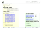
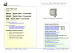
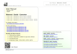
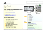
1
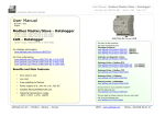
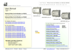
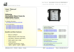
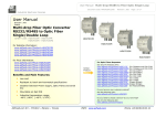
User Manual
GSM I/O and Alarms Modem
Document code: MN67302_ENG
Revision 1.100
Page 1 of 35
Industrial Electronic Devices
User Manual
Revision 1.100
English
GSM I/O and Alarms Modem
for Website information:
www.adfweb.com?Product=HD67302
for Price information:
www.adfweb.com?Price=HD67302-B2-02
www.adfweb.com?Price=HD67302-B2-20
www.adfweb.com?Price=HD67302-B2-11
Analyzer / Scanner /Sniffer, M-Bus
www.adfweb.com?Product=HD67031
Benefits and Main Features:
Very easy to configure
SMS / Call to get/trigger an input/output
Wide power input range
Temperature range: -20°C / +70°C (-4°F / +158°F)
HD67302-B2-xx
Multi-Drop Converter RS232/RS485 to Optic Fiber
www.adfweb.com?Product=HD67033M
(RS232, SL)
www.adfweb.com?Product=HD67034M
(RS232, DL)
www.adfweb.com?Product=HD67035M
(RS485, SL)
www.adfweb.com?Product=HD67036M
(RS485, DL)
Isolator & Repeater, RS485
www.adfweb.com?Product=HD67149-A1
CAN, CANopen, J1939, DeviceNet, NMEA2000 Analyzer
www.adfweb.com?Product=HD67316
CAN, CANopen, J1939, DeviceNet, NMEA2000 from/to USB
www.adfweb.com?Product=HD67390
Do you have an your customer protocol?
See the following links:
www.adfweb.com?Product=HD67003
Do you need to choose a device? do you want help?
User Manual
ADFweb.com Srl – IT31010 – Mareno – Treviso
Ask it to the following link:
www.adfweb.com?Cmd=helpme
INFO: www.adfweb.com
Phone +39.0438.30.91.31
User Manual
GSM I/O and Alarms Modem
Document code: MN67302_ENG
Revision 1.100
Page 2 of 35
Industrial Electronic Devices
UPDATED DOCUMENTATION:
INDEX:
INDEX
UPDATED DOCUMENTATION
REVISION LIST
WARNING
TRADEMARKS
SECURITY ALERT
EXAMPLE OF CONNECTION
CONNECTION SCHEME
CHARACTERISTICS
CONFIGURATION
POWER SUPPLY
FUNCTION MODES
LEDS
GSM
DIGITAL INPUT
DIGITAL OUTPUT
ANALOG INPUT
USB
USE OF COMPOSITOR SW67302
NEW CONFIGURATION
LOAD CONFIGURATION
DEVICE SETTING
INPUT SETTING
OUTPUT SETTING
PROFILES
DATE TIME SETTING
UPDATE DEVICE
SOFTWARE PREFERENCES
MECHANICAL DIMENSIONS
ORDERING INFORMATIONS
DISCLAIMER
OTHER REGULATIONS AND STANDARDS
WARRANTIES AND TECHNICAL SUPPORT
RETURN POLICY
Page
2
2
2
2
2
3
4
5
6
6
7
8
9
10
11
13
14
15
16
17
18
19
20
22
26
28
29
31
32
33
34
34
35
35
Dear customer, we thank you for your attention and we remind you
that you need to check that the following document is:
Updated
Related to the product you own
To obtain the most recently updated document, note the “document
code” that appears at the top right-hand corner of each page of this
document.
With
this
“Document
Code”
go
to
web
page
www.adfweb.com/download/ and search for the corresponding code on
the page. Click on the proper “Document Code” and download the
updates.
REVISION LIST:
Revision
0.900
1.000
1.001
1.100
Date
26/05/2011
03/09/2012
08/02/2013
15/06/2017
Author
Fl
Fl
Nt
Ff
Chapter
All
All
All
All
Description
First Release
Software changed (v1.008)
Added new chapters
New hardware version
WARNING:
ADFweb.com reserves the right to change information in this manual
about our product without warning.
ADFweb.com is not responsible for any error this manual may contain.
TRADEMARKS:
All trademarks mentioned in this document belong to their respective
owners.
ADFweb.com Srl – IT31010 – Mareno – Treviso
INFO: www.adfweb.com
Phone +39.0438.30.91.31
User Manual
GSM I/O and Alarms Modem
Document code: MN67302_ENG
Revision 1.100
Page 3 of 35
Industrial Electronic Devices
SECURITY ALERT:
GENERAL INFORMATION
To ensure safe operation, the device must be operated according to the instructions in the manual. When using the device, legal and
safety regulation are required for each individual application. The same applies also when using accessories.
INTENDED USE
Machines and systems must be designed so the faulty conditions do not lead to a dangerous situation for the operator (i.e.
independent limit switches, mechanical interlocks, etc.).
QUALIFIED PERSONNEL
The device can be used only by qualified personnel, strictly in accordance with the specifications.
Qualified personnel are persons who are familiar with the installation, assembly, commissioning and operation of this equipment and
who have appropriate qualifications for their job.
RESIDUAL RISKS
The device is state-of-the-art and is safe. The instruments can represent a potential hazard if they are inappropriately installed and
operated by untrained personnel. These instructions refer to residual risks with the following symbol:
This symbol indicates that non-observance of the safety instructions is a danger for people that could lead to serious injury or
death and / or the possibility of damage.
CE CONFORMITY
The declaration is made by our company. You can send an email to [email protected] or give us a call if you need it.
ADFweb.com Srl – IT31010 – Mareno – Treviso
INFO: www.adfweb.com
Phone +39.0438.30.91.31
User Manual
GSM I/O and Alarms Modem
Document code: MN67302_ENG
Revision 1.100
Page 4 of 35
Industrial Electronic Devices
EXAMPLE OF CONNECTION:
ADFweb.com Srl – IT31010 – Mareno – Treviso
INFO: www.adfweb.com
Phone +39.0438.30.91.31
User Manual
GSM I/O and Alarms Modem
Document code: MN67302_ENG
Revision 1.100
Page 5 of 35
Industrial Electronic Devices
CONNECTION SCHEME:
Figure 1: Connection scheme for HD67302-B2-xx
ADFweb.com Srl – IT31010 – Mareno – Treviso
INFO: www.adfweb.com
Phone +39.0438.30.91.31
User Manual
GSM I/O and Alarms Modem
Document code: MN67302_ENG
Revision 1.100
Page 6 of 35
Industrial Electronic Devices
CHARACTERISTICS:
The GSM I/O and Alarms Modem is a powerful, flexible and economic instrument which is used to control Digital and Analog I/O by SMS or
Phone Call.
It allows the following characteristics:
2 Digital Output (standard version);
2 Digital Input (standard version);
1 Analog Input (standard version);
SMS alert for state’s changing of the Digital/Analog Input;
Setting Output via SMS and/or call;
Mountable on 35mm Rail DIN;
Power Supply 8…24V AC or 12…35V DC;
Temperature range -20°C / +70°C (-4°F / +158°F).
CONFIGURATION:
You need Compositor SW67302 software on your PC in order to perform the following:
Define the Digital Input settings;
Define the Analog Input settings;
Define the Digital Output settings;
Set Date and Time;
Update the device.
ADFweb.com Srl – IT31010 – Mareno – Treviso
INFO: www.adfweb.com
Phone +39.0438.30.91.31
User Manual
GSM I/O and Alarms Modem
Document code: MN67302_ENG
Revision 1.100
Page 7 of 35
Industrial Electronic Devices
POWER SUPPLY:
The devices can be powered at 8…24V AC and 12…35V DC. The consumption depends to the code of the device. For more details see the two
tables below.
VAC
VDC
Vmin
Vmax
Vmin
Vmax
8V
24V
12V
35V
Consumption at 24V DC:
Device
[W/VA]
HD67302-B2-xx
3.5
Caution: Not reverse the polarity power
HD67302-B2-xx
ADFweb.com Srl – IT31010 – Mareno – Treviso
INFO: www.adfweb.com
Phone +39.0438.30.91.31
User Manual
GSM I/O and Alarms Modem
Document code: MN67302_ENG
Revision 1.100
Page 8 of 35
Industrial Electronic Devices
FUNCTION MODES:
The device has got two functions mode depending of the position of the ‘Dip1 of Dip-Switch A’:
The first, with ‘Dip1 of Dip-Switch A’ at “OFF” position, is used for the normal working of the device;
The second, with ‘Dip1 of Dip-Switch A’ at “ON” position, is used for uploading the Project and/or Firmware.
For the operations to follow for the updating, see ‘UPDATE DEVICE’ section.
According to the functioning mode, the LEDs will have specifics functions, see ‘LEDS’ section.
Warning:
Dip2 of ‘Dip-Switch A’ must be at ON position to work even if the Ethernet cable isn’t inserted.
ADFweb.com Srl – IT31010 – Mareno – Treviso
INFO: www.adfweb.com
Phone +39.0438.30.91.31
User Manual
GSM I/O and Alarms Modem
Document code: MN67302_ENG
Revision 1.100
Page 9 of 35
Industrial Electronic Devices
LEDS:
The device has got four LEDs that are used to give information of the functioning status.
The various meanings of the LEDs are described in the table below.
LED
Normal Mode
Boot Mode
1: Device state (green)
Blinks slowly (~1Hz)
2:GSM module comm.
(yellow)
Blinks quickly the GSM module is
communicating
Blinks quickly: Boot state
Blinks quickly when USB messages
are received
Blinks quickly: Boot state
3: USB comm. (yellow)
OFF: GSM connected
Blinks quickly: Boot state
ON: GSM not connected
Blinks very slowly (~0.5Hz): update in progress
Blinks quickly: Boot state
4: GSM comm. error
(yellow)
ADFweb.com Srl – IT31010 – Mareno – Treviso
Blinks very slowly (~0.5Hz): update in progress
Blinks very slowly (~0.5Hz): update in progress
Blinks very slowly (~0.5Hz): update in progress
INFO: www.adfweb.com
Phone +39.0438.30.91.31
User Manual
GSM I/O and Alarms Modem
Document code: MN67302_ENG
Revision 1.100
Page 10 of 35
Industrial Electronic Devices
GSM:
The HD67302 uses a Quad-band GSM/GPRS module and allows to send/receive SMS and
phone call.
The Antenna connector is a SMA Female (‘Female Outer Shell’ and ‘Female Receptacle’) so
the Antenna must have a SMA Male connector.
The SIM type is Micro-Sim.
ADFweb.com Srl – IT31010 – Mareno – Treviso
INFO: www.adfweb.com
Phone +39.0438.30.91.31
User Manual
GSM I/O and Alarms Modem
Document code: MN67302_ENG
Revision 1.100
Page 11 of 35
Industrial Electronic Devices
DIGITAL INPUTS:
Depending on the product code, you can identify what kind of inputs you have:
HD67302-B2-02: 2 Digital Inputs with driving on Positive wire;
HD67302-B2-20: 2 Digital Inputs with driving on Negative wire;
HD67302-B2-11: 1 Digital Input with driving on Positive wire and 1 Digital Input with driving on Negative wire.
Pin
1
2
3
4
Description
Positive wire
Negative wire
Positive wire
Negative wire
Port
Digital Input 1 (DI1)
Digital Input 2 (DI2)
Warning: Maximum voltage applied: 48V DC
Warning: Minimum voltage applied: 5V DC
Warning: In the case of HD67302-B2-11 Digital Input Port 1 (Connector 5) is Positive wire driving and Digital Input Port 2 (Connector 6) is
Negative wire driving
ADFweb.com Srl – IT31010 – Mareno – Treviso
INFO: www.adfweb.com
Phone +39.0438.30.91.31
User Manual
GSM I/O and Alarms Modem
Document code: MN67302_ENG
Revision 1.100
Page 12 of 35
Industrial Electronic Devices
POSITIVE WIRE CONTROL:
In this case the Input have a fixed signal that is the ground of the signal (Pin 2 / 4) and to the other Pin (1 / 3) there is the positive signal
that can be applied or not.
1/3
2/4
NEGATIVE WIRE CONTROL:
In this case the Input have the fixed signal in the Positive wire (Pin 1 / 3) and the other Pin (2 / 4) is driven, for example, by an Open
Collector output.
1/3
2/4
ADFweb.com Srl – IT31010 – Mareno – Treviso
INFO: www.adfweb.com
Phone +39.0438.30.91.31
User Manual
GSM I/O and Alarms Modem
Document code: MN67302_ENG
Revision 1.100
Page 13 of 35
Industrial Electronic Devices
DIGITAL OUTPUT:
The Digital Output are clean contact relay NO (normally opened).
Pin
1
2
3
4
Description
Relay
Relay
Relay
Relay
contact
contact
contact
contact
Port
Digital Output 1 (DO1)
Digital Output 2 (DO2)
Warning: Maximum current: 250mA.
Warning: Maximum voltage: 48V DC
ADFweb.com Srl – IT31010 – Mareno – Treviso
INFO: www.adfweb.com
Phone +39.0438.30.91.31
User Manual
GSM I/O and Alarms Modem
Document code: MN67302_ENG
Revision 1.100
Page 14 of 35
Industrial Electronic Devices
ANALOG INPUT:
The Analog Input is 0…10V DC type. The conversion is made by a 10-bit ADC.
Pin
1
2
Description
Negative wire
Positive wire (max 10V DC)
Port
Analog Input (AI)
Warning: Maximum voltage applied: 10V DC
ADFweb.com Srl – IT31010 – Mareno – Treviso
INFO: www.adfweb.com
Phone +39.0438.30.91.31
User Manual
GSM I/O and Alarms Modem
Document code: MN67302_ENG
Revision 1.100
Page 15 of 35
Industrial Electronic Devices
USB:
The USB port is used to program the module. It is necessary to use a Micro USB type B cable.
ADFweb.com Srl – IT31010 – Mareno – Treviso
INFO: www.adfweb.com
Phone +39.0438.30.91.31
User Manual
GSM I/O and Alarms Modem
Document code: MN67302_ENG
Revision 1.100
Page 16 of 35
Industrial Electronic Devices
USE OF COMPOSITOR SW67302:
To configure the Alarm Modem use the available software that runs with Windows called SW67302. It is downloadable on the site
www.adfweb.com and its operation is described in this document. (This manual is referenced to the last version of the software present on
our web site). The software works with MSWindows (XP, Vista, Seven, 8, 10; 32/64bit).
When launching the SW67302, the window below appears (Fig. 2).
Note:
It is necessary to have installed .Net Framework 4.
Figure 2: Main window for SW67302
ADFweb.com Srl – IT31010 – Mareno – Treviso
INFO: www.adfweb.com
Phone +39.0438.30.91.31
User Manual
GSM I/O and Alarms Modem
Document code: MN67302_ENG
Revision 1.100
Page 17 of 35
Industrial Electronic Devices
NEW CONFIGURATION:
By pressing the “New Configuration” button it
is possible to create a new project. It is possible
to define the name and the device type. Press
“OK” to create it.
It is possible to save a configuration by pressing
the “Save Configuration” button or save it as a
new one by pressing “Save as” button.
Figure 3: “New Configuration” window
ADFweb.com Srl – IT31010 – Mareno – Treviso
INFO: www.adfweb.com
Phone +39.0438.30.91.31
User Manual
GSM I/O and Alarms Modem
Document code: MN67302_ENG
Revision 1.100
Page 18 of 35
Industrial Electronic Devices
LOAD CONFIGURATION:
By pressing the “Load Configuration” button it
is possible to load an existing project by selecting
one of the list that appears.
A device configuration can also be imported or
exported:
To clone the configurations of a GSM I/O
and Alarms Modem in order to configure
another device in the same manner, it is
necessary to maintain the folder and all its
contents;
To clone a project in order to obtain a
different version of the project, it is
sufficient to duplicate the project folder
with another name and open the new
folder
with
the
button
“Load
Configuration”.
Figure 4: “Load Configuration” window
ADFweb.com Srl – IT31010 – Mareno – Treviso
INFO: www.adfweb.com
Phone +39.0438.30.91.31
User Manual
GSM I/O and Alarms Modem
Document code: MN67302_ENG
Revision 1.100
Page 19 of 35
Industrial Electronic Devices
DEVICE SETTING:
By pressing the “Phone Setting” button, it is possible to
select the device type and the general setting for the
management of the SIM card.
Under the section “Device Type”, it is possible to define
the device type and the general Ethernet settings
(incoming version).
Under the section “Phone Setting”, it is possible to
define:
in the field “Insert the PIN Code” the PIN code
of the SIM card;
if the field “Enable automatic switch in
“daylight saving time” and back (Only for
Europe)” is checked to enable the automatic
time setting described;
in the field “Max SMS for day” the maximum
number of SMS sent by the Alarm Modem.
Figure 5: “Device Setting” window
ADFweb.com Srl – IT31010 – Mareno – Treviso
INFO: www.adfweb.com
Phone +39.0438.30.91.31
User Manual
GSM I/O and Alarms Modem
Document code: MN67302_ENG
Revision 1.100
Page 20 of 35
Industrial Electronic Devices
INPUT SETTING:
DIGITAL SETTING
The Alarm Modem has two Digital Input. For both
of them it is possible to define the alert by SMS.
There are two possibilities:
Sending a SMS when the Input changing
from 0 to 1 by checking the field “Send
follow SMS when Digital Input change
from value 0 to value 1”;
Sending a SMS when the Input changing
from 1 to 0 by checking the field “Send
follow SMS when Digital Input change
from value 1 to value 0”.
For both cases, there is the possibility to insert
different phone numbers and different SMS texts.
The SMS will be sent only when the Input is set
to the other state for at least the time inserted in
the field “For a time major of ………
Milliseconds”.
Figure 6: “Input Setting
window
Digital Setting”
ADFweb.com Srl – IT31010 – Mareno – Treviso
INFO: www.adfweb.com
Phone +39.0438.30.91.31
User Manual
GSM I/O and Alarms Modem
Document code: MN67302_ENG
Revision 1.100
Page 21 of 35
Industrial Electronic Devices
ANALOG SETTING
The Alarm Modem has an Analog Input. It is
possible to define the alert by SMS.
There are two possibilities:
Sending a SMS when the Input goes
above a certain threshold voltage by
checking the field “Send follow SMS
when Analog Input is Higher than
……… Volt”;
Sending a SMS when the Input goes below
a certain threshold voltage by checking
the field “Send follow SMS when
Analog Input is Lower than ………
Volt”.
Figure 7: “Input Setting
Analog Setting” window
ADFweb.com Srl – IT31010 – Mareno – Treviso
For both cases there is the possibility to insert
different phone numbers, different SMS texts and
the hysteresis of the signal. The SMS will be sent
only when the Input is above or below for at least
the time inserted in the field “For a time major
of ……… Milliseconds”.
INFO: www.adfweb.com
Phone +39.0438.30.91.31
User Manual
GSM I/O and Alarms Modem
Document code: MN67302_ENG
Revision 1.100
Page 22 of 35
Industrial Electronic Devices
OUTPUT SETTING:
The device has two Digital Output. For both of them it is possible to define the modality of setting (SMS or phone call).
SMS
By pressing the field “SMS” it is possible to
enable the function of change the state of output
using a SMS.
There are three possibilities:
“SET output by SMS”, used for closing
the relay contact;
“RESET output by SMS”,
opening the relay contact;
used
for
“IMPULSE Output by SMS”, used
for sending a pulse with a defined
duration. The duration of the impulse is defined
with
the
field
“Pulse
duration
………
Milliseconds”. The maximum value that the
impulse can have is 60000ms.
Figure 8: “Output Setting
SMS” window
For all cases there is the possibility to insert, in the field on right, the text of the SMS used to trigger the event.
ADFweb.com Srl – IT31010 – Mareno – Treviso
INFO: www.adfweb.com
Phone +39.0438.30.91.31
User Manual
GSM I/O and Alarms Modem
Document code: MN67302_ENG
Revision 1.100
Page 23 of 35
Industrial Electronic Devices
If the field “Enabled on Phone Number” is checked, only the phone number written in the table is able to do the operation to the Digital
Output; otherwise all numbers that send the defined SMS are able to do the operation.
If the field “Enabled on Password” is checked, the SMS sent must contain the password written in the field near the command.
It is possible to write also other words in the SMS, it is just necessary that the SMS text contains exactly the text defined in the
compositor.
The Password can have a maximum length of 16 characters. All characters are accepted.
If the field “Send back an echo SMS” is checked, the device sends back to the sender the same SMS if the event is successful done.
In the table “Enabled users control phone number” it is possible to insert the various ‘Phone Numbers’ and for each Number give a ‘Profile’.
The possible ‘Profile’ are:
0: Always enabled;
1: Weekly 1;
2: Weekly 2;
3: Weekly 3;
4: Daily 1;
5: Daily 2;
6: Daily 3.
ADFweb.com Srl – IT31010 – Mareno – Treviso
INFO: www.adfweb.com
Phone +39.0438.30.91.31
User Manual
GSM I/O and Alarms Modem
Document code: MN67302_ENG
Revision 1.100
Page 24 of 35
Industrial Electronic Devices
CALL
By pressing the field “CALL” it is possible to
enable the function of change the state of output
using a phone call.
There are three types of operations:
“Automatic hang Up after Hang Up
Risings Number”, used to hang up after
the numbers of rings expressed in the
field “Hang Up Rings”;
“Under Ring Number”, used to trigger
an event if the number of rings is under
the value expressed in the field “Ring
Number”;
“Above Ring Number”, used to trigger
an event if the number of rings is above
the value expressed in the field “Ring
Number”.
Figure 9: “Output Setting
SMS” window
ADFweb.com Srl – IT31010 – Mareno – Treviso
INFO: www.adfweb.com
Phone +39.0438.30.91.31
User Manual
GSM I/O and Alarms Modem
Document code: MN67302_ENG
Revision 1.100
Page 25 of 35
Industrial Electronic Devices
For all operations, there are the three possibilities:
“Set output”, used for closing the relay contact;
“Reset output”, used for opening the relay contact;
“Impulse output”, used for making an impulse with a defined duration. The duration of the impulse is defined with the field “Pulse
duration ……… Milliseconds”.
In the table it is possible to insert the various ‘Phone Numbers’ and for each Number give a ‘Profile’.
The possible ‘Profile’ are the same described in the subsection ‘SMS’ of section ‘Output Setting’.
ADFweb.com Srl – IT31010 – Mareno – Treviso
INFO: www.adfweb.com
Phone +39.0438.30.91.31
User Manual
GSM I/O and Alarms Modem
Document code: MN67302_ENG
Revision 1.100
Page 26 of 35
Industrial Electronic Devices
PROFILES:
By pressing the “Prfoiles” button it is possible to set the Profiles inside the Alarm Modem. The Profiles are used to define which phone
numbers can control the Digital Outputs in which day/time.
WEEKLY
There is the possibility to define up to three
Weekly Profile “Weekly 1”, “Weekly 2”,
“Weekly 3”.
For enabling the Profile, the field “Enable Profile
Weekly X” must be checked.
For each day there are 48 time slot of 30 minutes
each.
In order to use one of Weekly Profiles, it is
necessary to select them in the “Output
Setting SMS”
or
“Output
Setting CALL”
sections.
Figure 10: “Profiles
Weekly” window
ADFweb.com Srl – IT31010 – Mareno – Treviso
INFO: www.adfweb.com
Phone +39.0438.30.91.31
User Manual
GSM I/O and Alarms Modem
Document code: MN67302_ENG
Revision 1.100
Page 27 of 35
Industrial Electronic Devices
DAILY
There is the possibility to define up to three Daily
Profile “Daily”.
For enabling the Profile, the field “Enable Profile
Daily X” must be checked.
For each day there are 48 time slot of 30 minutes
each.
In order to use one of Weekly Profiles, it is
necessary to select them in the “Output
Setting SMS”
or
“Output
Setting CALL”
sections.
Figure 11: “Profiles
Daily” window
ADFweb.com Srl – IT31010 – Mareno – Treviso
INFO: www.adfweb.com
Phone +39.0438.30.91.31
User Manual
GSM I/O and Alarms Modem
Document code: MN67302_ENG
Revision 1.100
Page 28 of 35
Industrial Electronic Devices
DATE & TIME SETTING:
By pressing the “Date Time Setting” button it is possible to change the Date & Time of the device.
DATE & TIME
In this section it is possible to change the Date &
Time of the device.
There are two possibilities:
Insert an own Date & Time, by compiling
the fields “hh”, ”mm”, ”ss”, ”dd”, ”mm”,
”yy”; and then pressing the button “Set
Custom Date & Time”;
Insert the PC date & Time, by pressing the
button “Set PC Date & Time”.
It is possible also read the Date & Time of the
device and also the Firmware Version by pressing
the “Read Status Device” button.
For doing these operations it is necessary to
connect the device through the USB to the PC
and select the COM port.
The device must be at Normal Mode.
For the year (yy) only the last two digits
must be inserted.
Figure 12: “Date Time Setting
Date Time” window
ADFweb.com Srl – IT31010 – Mareno – Treviso
INFO: www.adfweb.com
Phone +39.0438.30.91.31
User Manual
GSM I/O and Alarms Modem
Document code: MN67302_ENG
Revision 1.100
Page 29 of 35
Industrial Electronic Devices
UPDATE DEVICE:
By pressing the “Update Device” button it is
possible to load the created Configuration into the
device; and also the Firmware, if it is necessary.
In order to load the parameters or update the
firmware in the device, follow these instructions:
Connect the USB cable from your PC to the
Converter;
Select the “COM port”;
Select which operations you want to do.
Press the “Update Device” button to start
the upload;
When all the operations
disconnect the USB cable.
are
“OK”,
At this point the configuration/firmware on the
device is correctly update.
Figure 13: “Update device” windows
ADFweb.com Srl – IT31010 – Mareno – Treviso
INFO: www.adfweb.com
Phone +39.0438.30.91.31
User Manual
GSM I/O and Alarms Modem
Document code: MN67302_ENG
Revision 1.100
Page 30 of 35
Industrial Electronic Devices
Note:
When you install a new version of the software it is better if the first time you do the update of the Firmware in the HD67302 device.
Note:
When you receive the device, for the first time, you have to update also the Firmware in the HD67302 device.
Warning:
If the Fig. 14 appears when you try to do the Update before require assistance try these points:
Check if the serial COM port selected is the correct one;
Check if the USB cable is connected between the PC and the device;
Try to repeat the operations for the updating;
Try with another PC;
Try to restart the PC;
If you are using the program inside a Virtual Machine, try to use in the main
Operating System;
If you are using Windows Seven or Vista or 8 or 10, make sure that you have the
administrator privileges;
Figure 14: “Protection” window
Pay attention to Firewall lock.
ADFweb.com Srl – IT31010 – Mareno – Treviso
INFO: www.adfweb.com
Phone +39.0438.30.91.31
User Manual
GSM I/O and Alarms Modem
Document code: MN67302_ENG
Revision 1.100
Page 31 of 35
Industrial Electronic Devices
SOFTWARE PREFERENCES:
By pressing the “Software preferences” button
it is possible to define the preferences of the
software.
Figure 15: “Software preferences” window
ADFweb.com Srl – IT31010 – Mareno – Treviso
INFO: www.adfweb.com
Phone +39.0438.30.91.31
User Manual
GSM I/O and Alarms Modem
Document code: MN67302_ENG
Revision 1.100
Page 32 of 35
Industrial Electronic Devices
MECHANICAL DIMENSIONS:
Figure 16: Mechanical dimensions scheme for HD67302-B2-xx
ADFweb.com Srl – IT31010 – Mareno – Treviso
INFO: www.adfweb.com
Phone +39.0438.30.91.31
User Manual
GSM I/O and Alarms Modem
Document code: MN67302_ENG
Revision 1.100
Page 33 of 35
Industrial Electronic Devices
ORDERING INFORMATIONS:
The ordering part number is formed by a valid combination of the following:
HD67302 – B 2 – xx
Digital Input Type
02 = two Digital Input with Positive wire control
20 = two Digital Input with Negative wire control
11 = one Digital Input with Positive wire control and one Digital Input with Negative wire control
Connectors Type
2 = Fixed Screw Terminal
Enclosure Type
B = Modulbox 4M DIN Rail mounting
Device Family
HD67302 = GSM I/O and Alarms Modem
Order Code: HD67302-B2-02
-
GSM I/O and Alarms Modem with two Digital Input with Positive wire control
Order Code: HD67302-B2-20
-
GSM I/O and Alarms Modem with two Digital Input with Negative wire control
Order Code: HD67302-B2-11
-
GSM I/O and Alarms Modem with one Digital Input with Positive wire control and one Digital
Input with Negative wire control
ADFweb.com Srl – IT31010 – Mareno – Treviso
INFO: www.adfweb.com
Phone +39.0438.30.91.31
User Manual
GSM I/O and Alarms Modem
Document code: MN67302_ENG
Revision 1.100
Page 34 of 35
Industrial Electronic Devices
DISCLAIMER:
All technical content within this document can be modified without notice. The content of the document is a under continual renewal.
For losses due to fire, earthquake, third party access or other accidents, or intentional or accidental abuse, misuse, or use under abnormal
conditions repairs are charged to the user. ADFweb.com S.r.l. will not be liable for accidental loss of use or inability to use this product, such
as loss of business income. ADFweb.com S.r.l. shall not be liable for consequences of improper use.
OTHER REGULATIONS AND STANDARDS:
WEEE INFORMATION
Disposal of old electrical and electronic equipment (as in the European Union and other European countries with separate
collection systems).
This symbol on the product or on its packaging indicates that this product may not be treated as household rubbish. Instead, it
should be taken to an applicable collection point for the recycling of electrical and electronic equipment. If the product is disposed
correctly, you will help prevent potential negative environmental factors and impact of human health, which could otherwise be
caused by inappropriate disposal. The recycling of materials will help to conserve natural resources. For more information about
recycling this product, please contact your local city office, your household waste disposal service or the shop where you purchased
the product.
RESTRICTION OF HAZARDOUS SUBSTANCES DIRECTIVE
The device respects the 2002/95/EC Directive on the restriction of the use of certain hazardous substances in electrical
and electronic equipment (commonly referred to as Restriction of Hazardous Substances Directive or RoHS).
CE MARKING
The product conforms with the essential requirements of the applicable EC directives.
ADFweb.com Srl – IT31010 – Mareno – Treviso
INFO: www.adfweb.com
Phone +39.0438.30.91.31
User Manual
GSM I/O and Alarms Modem
Document code: MN67302_ENG
Revision 1.100
Page 35 of 35
Industrial Electronic Devices
WARRANTIES AND TECHNICAL SUPPORT:
For fast and easy technical support for your ADFweb.com SRL products, consult our internet support at www.adfweb.com.
Otherwise contact us at the address [email protected]
RETURN POLICY:
If while using your product you have any problem and you wish to exchange or repair it, please do the following:
Obtain a Product Return Number (PRN) from our internet support at www.adfweb.com. Together with the request, you need to
provide detailed information about the problem.
Send the product to the address provided with the PRN, having prepaid the shipping costs (shipment costs billed to us will not be
accepted).
If the product is within the warranty of twelve months, it will be repaired or exchanged and returned within three weeks. If the product is no
longer under warranty, you will receive a repair estimate.
ADFweb.com S.r.l.
Via Strada Nuova, 17
IT-31010 Mareno di Piave
TREVISO (Italy)
Phone +39.0438.30.91.31
Fax +39.0438.49.20.99
www.adfweb.com
ADFweb.com Srl – IT31010 – Mareno – Treviso
INFO: www.adfweb.com
Phone +39.0438.30.91.31