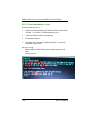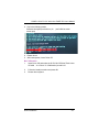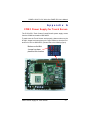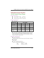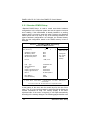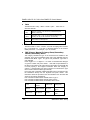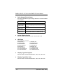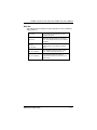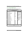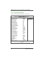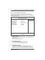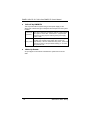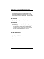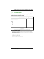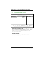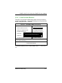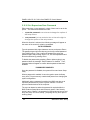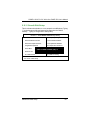
1
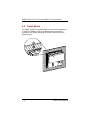
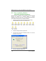
PANEL1150-675 All-in-One 15.0” Super Slim PANEL PC User’s Manual Disclaimers The information in this manual has been carefully checked and is believed to be accurate. AXIOMTEK Co., Ltd. assumes no responsibility for any infringements of patents or other rights of third parties, which may result from its use. AXIOMTEK assumes no responsibility for any inaccuracies that may be contained in this document. AXIOMTEK makes no commitment to update or to keep current the information contained in this manual. AXIOMTEK reserves the right to make improvements to this document and/or product at any time and without notice. No part of this document may be reproduced, stored in a retrieval system, or transmitted, in any form or by any means, electronic, mechanical, photocopying, recording, or otherwise, without the prior written permission of AXIOMTEK Co., Ltd. ©Copyright 2004 by AXIOMTEK Co., Ltd. All rights reserved. April 2005, Version A2 Printed in Taiwan ii Safety Approvals CE Marking FCC Class A FCC Compliance This equipment has been tested and complies with the limits for a Class A digital device, pursuant to Part 15 of the FCC Rules. These limits are designed to provide reasonable protection against harmful interference in a residential installation. If not installed and used in accordance with proper instructions, this equipment might generate or radiate radio frequency energy and cause harmful interference to radio communications. However, there is no guarantee that interference will not occur in a particular installation. If this equipment does cause harmful interference to radio or television reception, which can be determined by turning the equipment off and on, the user is encouraged to try to correct the interference by one or more of the following measurers: 1. Reorient or relocate the receiving antenna. 2. Increase the separation between the equipment and receiver. 3. Connect the equipment into an outlet on a circuit different from that to which the receiver is connected. 4. Consult the dealer technician for help. or an experienced radio/TV Shielded interface cables must be used in order to comply with emission limits.ou iii Safety Precautions Before getting started, read the following important cautions. 1. The PANEL1150-675 does not come equipped with an operating system. An operating system must be loaded first before installing any software into the computer. 2. Be sure to ground yourself to prevent static charge when installing the internal components. Use a grounding wrist strap and place all electronic components in any static-shielded devices. Most electronic components are sensitive to static electrical charge. 3. Disconnect the power cord from the PANEL1150-675 before making any installation. Be sure both the system and the external devices are turned OFF. Sudden surge of power could ruin sensitive components. Make sure the PANEL1150-675 is properly grounded. 4. The brightness of the flat panel display decreases with usage. However, hours of use vary depending on the application environment. 5. Turn OFF the system power before cleaning. Clean the system using a cloth only. Do not spray any liquid cleaner directly onto the screen. The PANEL1150-675 may come with or w/o a touchscreen. Although the touchscreen is chemical resistant, it is recommended that you spray the liquid cleaner on a cloth first before wiping the screen. In case your system comes without the touchscreen, you must follow the same procedure and not spray any cleaner on the flat panel directly. 6. Avoid using sharp objects to operate the touchscreen. Scratches on the touchscreen may cause malfunction or internal failure to the touchscreen. 7. The flat panel display is not susceptible to shock or vibration. When assembling the PANEL1150-675, make sure it is securely installed. iv 8. Do not open the system’s back cover. If opening the cover for maintenance is a must, only a trained technician is allowed to do so. Integrated circuits on computer boards are sensitive to static electricity. To avoid damaging chips from electrostatic discharge, observe the following precautions: 9 Before handling a board or integrated circuit, touch an unpainted portion of the system unit chassis for a few seconds. This will help to discharge any static electricity on your body. 9 When handling boards and components, wear a wrist-grounding strap, available from most electronic component stores. Trademarks Acknowledgments AXIOMTEK is a trademark of AXIOMTEK Co., Ltd. IBM, PC/AT, PS/2, VGA are trademarks of International Business Machines Corporation. Intel and Pentium are trademarks of Intel Corporation. MS-DOS, Microsoft C and QuickBASIC are trademarks of Microsoft Corporation. VIA is a trademark of VIA Technologies, Inc. SST is a trademark of Silicon Storage Technology, Inc. UMC is a Corporation. trademark of United Microelectronics Other brand names and trademarks are the properties of their respective owners. v Table of Contents Chapter 1.1 1.2 1.2.1 system 1.2.2 1.2.3 1.2.4 1.3 1.4 1.5 1 Introduction............................................1 General Description......................................1 Specifications ...............................................2 Core System for PANEL1150-675 SBC83675-based 2 I/O System ........................................................... 3 Built-in Peripherals .............................................. 4 System Specification .......................................... 4 Dimensions ...................................................5 I/O Outlets......................................................7 Utilities Supported........................................8 C h a p t e r 2 System Configuration ........................17 2.1 2.1.1 2.2 System Configuration ................................17 Front View .......................................................... 17 Panel Mount ................................................18 C h a p t e r 3 System Installation ...............................19 3.1 3.2 3.3 3.3.1 3.3 3.4 3.5 3.6 3.7 3.8 3.9 3.10 Chapter 4.1 4.2 vi CPU, HDD, and DRAM Installation ............20 FDD Installation ..........................................22 CD-ROM Installation ...................................24 Package ............................................................ 24 3 x Serial Ports............................................27 Parallel Port.................................................28 VGA ..............................................................28 Ethernet .......................................................28 Digital I/Os ...................................................29 Keyboard .....................................................29 Riser Card Assembly..................................30 PS/2 Mouse..................................................31 4 Driver Installation..................................32 System .........................................................32 Touch Screen ..............................................33 4.2.1 Specification ..................................................... 33 4.2.2 Driver Installation- Windows 98/2000/XP/CE.NET/XP-Embedded................................ 34 4.2.3 Driver Installation- DOS..................................... 36 4.2.4 Driver Installation- Linux ................................... 38 A p p e n d i x A COM 3 Power Supply for Touch Screen ...................................................................................41 Appendix B Power Supply Specifications .......43 Appendix C SBC83675 BIOS Setup...................50 vii PANEL1150-675 15.0” All-in-One PANEL PC User’s Manual Chapter 1 Introduction This chapter contains the general information and the detail specifications of the PANEL1150-675. Chapter 1 includes the following sections: z General Description z System Specification z Dimensions z I/O Outlets z Utilities Supported 1.1 General Description The PANEL1150-675 super slim industrial PANEL PC is mainly designed for industrial automation and some space-constricted embedded applications. For some space-concerned industries, a traditional PC with a separate main system, display monitor and keyboard is too complex for system integration. Ruggedly designed Industrial Panel PC, the PANEL1150-675, is an all-in-one system which is 100% IBM PC/AT compatible. It includes integrated 15.0” TFT LCD, touch screen, super I/Os, Ethernet, and packs special industrial features like watchdog timer, CMOS double backup. The industrial-graded PANEL1150-675 can be easily applied to any embedded applications. It allows the system to continuously operate in any hostile industrial environments where stability and reliability is a must. Common applications of the PANEL1150-675 include tooling machine, POI terminal, stand-alone KIOSK, medical instrument, mobile communication device and banking system - to name just a few. Designed by the Industrial PC experts, the PANEL1150-675 is virtually the ultimate one-step solution for your space-limited applications. Introduction 1 PANEL1150-675 15.0” All-in-One PANEL PC User’s Manual 1.2 Specifications 1.2.1 Core System for PANEL1150-675 SBC83675-based system z CPU: Intel Celeron 533MHz ~ 1.3G MHz; Intel Pentium III 550 ~ 1.4G MHz VIA Cyrix-III/C3 Family at 100/133MHz FSB z System Chipset: VIA VT8606(Twist-T) + VT82C686B z BIOS: Phoenix-Award BIOS, 4Mbit with RPL/PXE LAN boot ROM, SmartView and customer BIOS backup. z System Memory: One 168-pin DIMM Socket Maximum of 512MB SDRAM ECC/parity z L2 Cache: Integrated in CPU z Bus Clock: 66/100/133 MHz z Watchdog Timer: Generates a system reset or NMI by jumper selectable; software programmable Time interval; 64 levels, 0.5~8 / 5~80 / 50~800 / 100~1600 seconds 2 Introduction PANEL1150-675 15.0” All-in-One PANEL PC User’s Manual 1.2.2 I/O System z Standard I/O: 4 x serial ports with power; 3 x RS-232, 1 x RS-232/422/485 jumper selectable 1 x parallel port, SPP/EPP/ECP 1 x Keyboard Interface 1 x PS/2 Mouse Interface 2 x USB Ports 1.1 compliant z Digital I/O: Input x 4, Output x 4 z Ethernet: z z Realtek RTL 8100C PCI Bus 10/100M Base-T Wake-On-LAN RJ-45 interface equipped Audio: AC-97 Codec 32-bit Sound Blaster and sound Pro compatible 16-bit stereo ADC and DAC PC97/PC98 and WHQL specifications Full-duplex operation for simultaneous record and playback Internal MIC-in, Line-in, Speaker/Line-out interface reserved VGA/Flat Panel Controller: VIA Twister chip with integrated S3 Pro Savage4 2D/3D/Video accelerator 8/16/32MB frame buffer sharing system memory Supports up to 1280 X 1024 256-color resolution on noninterlaced CRT monitors, and 1024 x 768 16 bit-color on LCD panel monitors Introduction 3 PANEL1150-675 15.0” All-in-One PANEL PC User’s Manual 1.2.3 Built-in Peripherals z 15.0” TFT LCD z 15.0” anti-glare analog resistive touch screen with RS- 232 controller sharing COM3 z Slim Floppy Drive z System cooling fan z 100W AC power supply 1.2.4 System Specification z 15.0” TFT with 1024 x 768 resolution z NEMA 4/12 sealed front panel z 24X slim type CD-ROM drive (Optional) z Slim floppy disk drive z Heat dispensing design z Two free slots for PCI/ISA and ISA expansion, or two free slots for PCI/ISA and PCI expansion This slot only comes standard with the riser card assembly. Net weight: z 7.7 Kgs (without the riser card assembly mounted) 8.8 Kgs. (with the riser card assembly mounted) Dimension (main body size): z 433 x 358 x 91.30 mm (without the riser card assembly mounted) 433 x 358 x 145.5 mm (with the riser card assembly mounted) z Operating Temperature Range: 0 o C ~ 45 o C z Relative Humidity: 5% ~ 95%; non-condensing 4 Introduction PANEL1150-675 15.0” All-in-One PANEL PC User’s Manual 1.3 Dimensions The following diagrams show the dimensions and outlines of PANEL1150-675. Introduction 5 PANEL1150-675 15.0” All-in-One PANEL PC User’s Manual 6 Introduction PANEL1150-675 15.0” All-in-One PANEL PC User’s Manual 1.4 I/O Outlets The following figure shows the I/O locations of the PANEL1150-675. Most of the I/O connectors are located on the back panel of the PANEL1150-675. 1: CD-ROM 10: VGA Port 2: Slim FDD 11: COM1 3: Power Switch 12: COM2 4: AC inlet 13: COM4 5: USB v1.1 14: PRN (Parallel Port) 6: USB v1.1 15: DIO (4Channel Digital Inputs/Outputs) 7: LAN (RJ45) 16: Line-In 8: Keyboard 17: MIC 9: Mouse 18: Line-Out Introduction 7 PANEL1150-675 15.0” All-in-One PANEL PC User’s Manual 1.5 Utilities Supported z Watchdog Utility z Ethernet Utility z VGA Drivers z Touch screen Utility 8 Introduction PANEL1150-675 15.0” All-in-One PANEL PC User’s Manual Chapter 2 System Configuration This chapter details the system parts and components with figures. Sections include z System Major Parts z Panel Mount 2.1 System Configuration 2.1.1 Front View The figure below shows the features and controls on the PANEL1150-675 front panel. System Configuration 17 PANEL1150-675 15.0” All-in-One PANEL PC User’s Manual 2.2 Panel Mount The PANEL1150-675 is mainly designed for panel mount application. To mount the PANEL1150-675, the standard set of mounting kit (included in the system packaging) is needed. Please refer to the following figure. 18 System Configuration PANEL1150-675 15.0” All-in-One PANEL PC User’s Manual Chapter 3 System Installation This chapter describes the system installation and the cable connection to the I/O connectors. See system board User’s Manual that came with your PANEL PC packaging for more details. Sections in this chapter includes z CPU z DRAM z HDD z 3 x Serial Ports z Parallel Port z VGA z Ethernet z Digital I/O z Keyboard z PS/2 Mouse z Expansion Slot z System O/S and Software Installation The PANEL1150-675 has a Pentium III little board with a free ISA and PCI slots inside the riser card assembly. It already builds in a Pentium III CPU, relevant DRAM and a 3.5” HDD (or Dual 2.5” optional HDD). These are all standard and the system is ready to play. System performance can be increased by upgrading to a higher performance CPU, higher capacity DRAM modules and hard disk drive. The user can use the I/O ports located at the backside of the chassis to connect external peripheral devices, such as a monitor, serial devices, parallel printer…etc. NOTE: Make sure the power cord is disconnected before any installation. To install any internal device such as CPU, DRAM and HDD, take out the rear chassis cover first. System Installation 19 PANEL1150-675 15.0” All-in-One PANEL PC User’s Manual 3.1 CPU, HDD, and DRAM Installation The standard PANEL1150-675 system was designed Pentium III / Celeron level CPUs, and a 3.5” (or Dual 2.5”) hard disk drives. The build-in CPU board, SBC83675, provides one 168-pin DIMM socket that supports system memory up to 512MB. When upgrading the CPU, HDD, or DRAM, refer to the following illustration and instructions: HDD Bracket DRAM 20 CPU System Installation PANEL1150-675 15.0” All-in-One PANEL PC User’s Manual z Remove the 3 screws securing the riser card assembly’s back cover. Take off the cover by sliding it outward and pulling it upwards as pointed by the arrows. If your system does not come with a riser card assembly. z Another 6 screws, located on the upper perimeter (3) and lower half (3), needs to be removed. These screws are the screws bolting the system’s rear cover to the main unit. z You may now take off the system’s rear cover (along with the riser card assembly). z See the illustration for the exact locations of your HDD, CPU and DRAM sockets. z After making the necessary upgrades or modifications to your HDD, CPU, and DRAM, restore the system back to its original form by following instructions 4 to 1. System Installation 21 PANEL1150-675 15.0” All-in-One PANEL PC User’s Manual 3.2 FDD Installation When upgrading the CD-ROM or FDD, refer to the following illustration and instructions: z Remove the 3 screws securing the riser card assembly’s back cover. Take off the cover by sliding it outward and pulling it upwards as pointed by the arrows. If your system does not come with a riser card assembly. z Another 6 screws, located on the upper perimeter (3) and lower half (3), needs to be removed. These screws are the screws bolting the system’s rear cover to the main unit. z You may now take off the system’s rear cover (along with the riser card assembly). z See the illustration for the exact locations of your CD-ROM and FDD slots. There are 2 screws mounted on the cover of each slot. Remove these screws. Store the covers at a safe place for future use. z Mount the FDD and CD-ROM drives as shown on the illustration. Make sure to secure the drives using all 8 screws located on both sides of the expansion bay. z After completing the installation, restore the system back to its original form by following instructions 3 to 1. 22 System Installation PANEL1150-675 15.0” All-in-One PANEL PC User’s Manual System Installation 23 PANEL1150-675 15.0” All-in-One PANEL PC User’s Manual 3.3 CD-ROM Installation In order to reduce the unnecessary cost burden for the customer, AXIOMTEK offers the CD-ROM Kit as an optional accessory. Customer can install the CD-ROM by themselves with the following simple steps. Note: There is the electrical limitation, so it is only installed one from Axiomtek’s standard CD-ROM kit. 3.3.1 Package There are four major components in the package: z Slim CD-ROM Drive(1) z CD-ROM FPC Cable(2) z CD-ROM Holder(3) z Screws(4) (2) (1) (4) (3) (4) Remove the 3 screws securing the riser card assembly’s back cover. Take off the cover by sliding it outward and pulling it upwards as pointed by the z 24 System Installation PANEL1150-675 15.0” All-in-One PANEL PC User’s Manual arrows. If your system does not come with a riser card assembly. System Installation 25 PANEL1150-675 15.0” All-in-One PANEL PC User’s Manual z Another 6 screws, located on the upper perimeter (3) and lower half (3), needs to be removed. These screws are the screws bolting the system’s rear cover to the main unit. z You may now take off the system’s rear cover (along with the riser card assembly). z Remove the HDD holders. z Slide the CD-ROM to the Holder and fasten by two screws on both sides. z Slide the CD-ROM Holder to the Panel1150 and fasten the hold to the chassis by two screws. z Connect the FPC Cable to both CD-ROM and the I/O board. (as the following figure) z After completing the installation, restore the system back to its original form by following instructions 3 to 1. Connection to CD-ROM 26 Connection to I/O Board System Installation PANEL1150-675 15.0” All-in-One PANEL PC User’s Manual 3.3 3 x Serial Ports The PANEL1150-675 provides four onboard serial ports installed on the back bottom side of the chassis. For systems, COM1 and COM2 are RS-232 and COM4 is RS-232/422/485. Each serial port is with +5V/+12V power capabilities on both Pin 1 and Pin 9, ready to accommodate a wide array of serial devices, such as fax modem, scanner, serial mouse and touch screen...etc. If the touch screen option is included, its controller will share COM3. COM1 to COM4 are all D-SUB 9-pin connectors. To connect any serial devices, just plug in the device connector to the 9-pin D-SUB. In terms of transmission distance, the RS-422/485 will perform better than RS-232. In this case, COM2 is suggested to be set to RS-422/485 and the related jumpers have to be set correctly first (see the system board User’s Manual). The RS-422/485 pin assignment is listed as follows; Pin # 1 2 6 3 7 4 8 System Installation 5 9 Signal Name R2-422 RS-485 1 2 3 4 5 6 7 TXNo connector TX+ No connector RX+ No connector RX- DATANo connector DATA+ No connector No connector No connector No connector 8 9 10 No connector GND No connector No connector GND No connector 27 PANEL1150-675 15.0” All-in-One PANEL PC User’s Manual 3.4 Parallel Port The printer interface is a 25-pin D-SUB connector. To connect any parallel device, just plug in the device connector to the 25-pin D-SUB. 3.5 VGA The PANEL1150-675 has an analog RGB interface connector. It is able to connect to an expansion CRT monitor, and the system can display on both the flat panel and the CRT simultaneously. 3.6 Ethernet The PANEL1150-675 provides an NE2000 compatible Ethernet (RJ-45) interface. For network connection, just plug in one cable end of the PANEL1150-675 100-Base-T Hub into the standard RJ-45 connector. The pin assignment of the RJ-45 is listed below; RJ-45 Connector Pin Assignment 1 2 3 4 5 6 7 8 RJ-45 Pin Description 1 Tx+ (Data transmission positive) 2 Tx- (Data transmission negative) 3 Rx+(Data reception positive) 6 Rx- (Data reception negative) others Not use 28 System Installation PANEL1150-675 15.0” All-in-One PANEL PC User’s Manual 3.7 Digital I/Os The PANEL1150-675 provides a digital I/O of 4-channel inputs/outputs for simple automation control. For example, it can be used to control the opening and closing of the cash drawer on a POS system. It can also be used for UPS control. It comes with a 15-pin D-SUB connector, and its pin position and pin assignment is shown on the following page. Digital I/O Pin Assignment 1 6 2 11 12 3.8 7 3 8 4 9 5 10 13 14 15 P1 OUT 1 P9 GND P2 OUT 2 P10 GND P3 OUT 3 P11 IN1 P4 OUT4 P12 IN2 P5 GND P13 IN3 P6 GND P14 IN4 P7 GND P15 GND P8 GND Keyboard The PANEL1150-675 provides a standard PS/2 keyboard connector. System Installation 29 PANEL1150-675 15.0” All-in-One PANEL PC User’s Manual 3.9 Riser Card Assembly The PANEL1150-675 can be equipped with an optional riser card for PCI or ISA slots expansion. There are 2 riser card options available for PANEL1150-675, 1PCI/2ISA or 2PCI/2ISA. The riser card assembly directly plugs its riser card onto the PISA slot on SBC83675. This makes the PANEL1150-675 flexible for versatile applications. When no riser card assembly is needed, a metal cover is placed on the PISA slot opening. The riser card assembly is made up of two sections: the main cabinet and the cover. The main cabinet has 3 internal and 3 external screws that secure the cabinet tightly on the PANEL1150-675. The cover on the other hand, also has 6 screws that hold it to the main cabinet, 3 on each side. The riser card assembly can accommodate both half-size and/or full-size expansion cards. To install the riser card and riser card assembly onto the main unit, refer to the following figure and instructions below: z Take off the rear cover of the riser card assembly by pushing it sideways and then pulling it up, as shown by the arrows. z There are 4 screw holes located at the bottom of the assembly that indicate the riser card placement. Fasten the riser card as shown in the figure. z Plug either an ISA or PCI card into the ISA or PCI slot on the riser card and screw the expansion card to the metal opening piece. All the connectors of the expansion card will come out from the opening along the side for further connection. z Plug the riser card into the onboard PCI and ISA slots. z Mount the riser card assembly onto the main system by fastening 4 screws, working from within the riser card assembly. 30 System Installation PANEL1150-675 15.0” All-in-One PANEL PC User’s Manual z Slide the riser card assembly’s rear cover back into place. Screw the lid back to the main section by fastening 3 more screws located on top of the cover. 3.10 PS/2 Mouse The PANEL1150-675 has one PS/2 mouse connector. A simple plug-in will make the connection. System Installation 31 PANEL1150-675 15.0” All-in-One PANEL PC User’s Manual Chapter 4 Driver Installation 4.1 System PANEL1150-675 could support with Windows 95, Windows 98 or Windows 2000/XP. To facilitate installation system driver, you should read the instructions in this chapter carefully before you attempt installation. 1. Insert Driver CD and select the \P1150-675\Driver\.. 2. Select all files and follow the install procedure and press OK. 32 Driver Installation PANEL1150-675 15.0” All-in-One PANEL PC User’s Manual 4.2 Touch Screen 4.2.1 Specification Touch Screen: For 8-wire analog resistive type Touch Screen Controller: DMC9000 Communications: RS-232 Baud Rate: 19200 baud rate fixed Resolution: 1024 x 1024 (10-bit A/D converter inside) Power Input: 5V to 12V DC Power Consumption: 12V: 27mA+ i where (i = v/touch screen sheet R) 5V: 23mA+ i where (i = v/touch screen sheet R) Board Size: 6.0 x 2.0 cm Portrait: Support 90o to 270o screen rotation Static Protection: ESD device option Others: Touch activate indication LED on board Driver Installation 33 PANEL1150-675 15.0” All-in-One PANEL PC User’s Manual 4.2.2 Driver Installation- Windows 98/2000/XP/CE.NET/XP-Embedded The touch screen of PANEL1150-675 provides a driver for use with Windows 95, Windows 98 or Windows 2000/XP. To facilitate installation of the touch screen driver, you should read the instructions in this chapter carefully before you attempt installation. 1. Insert Driver CD and select the D:\P1150-675\Driver\Touch screen\Windows 9x or 2k or XP or CE\Setup.exe 2. Follow the install procedure and press OK. 3. Click Start menu and select “PenMount Utilities”. You can see PenMount Control Panel 4. Select the “Standard Calibrate” tab 34 Driver Installation PANEL1150-675 15.0” All-in-One PANEL PC User’s Manual 5. Calibration: To adjust the display with touch panel, click “Calibration” and follow the calibrate point to do calibration; there are five points on screen for calibration. 6. Press OK. Driver Installation 35 PANEL1150-675 15.0” All-in-One PANEL PC User’s Manual 4.2.3 Driver Installation- DOS Using “INSTALL.EXE” software driver. utility to install PenMount 1. Insert Driver CD and select the D:\P1150-675\Driver\Touch screen\DOS\ Install.exe 2. Press ENTER key to install the drivers to drive C or use keyboard to key-in the hard disc drive that you plan to install the driver. 3. The driver will ask “Do you want to modify your Autoexec.bat to initialize PenMount? (Y/N)” Suggest you choose “YES” for generating the initialization instructions in AUTOEXEC.BAT files. Then follow up the instructions to complete the installation. Identify the communication port and IRQ number 1. For the first time installation, or changing PenMount Touch Screen’s COM port, use PMDETECT (e.g. C:\PENMOUNT\PMDETECT) to check the COM port and IRQ number. PMDETECT will save the correct data to PMOUSE.CFG file for further use. The driver detects your communication COM port and IRQ number from COM1 IRQ4, COM2 IRQ3, COM3…. to COM4 IRQ15. PenMount driver can find the COM port and IRQ number automatically. The screen will then show: PenMount is initialized successfully!!! Create file “pmouse.cfg”. Success. PenMount internal settings: Comm. Port: COM<n> IRQ<n> .......... 1. PMDETECT program is able to skip the IRQ number detecting if you Touchscreen Driver Installation 13 do not need to detect the specified IRQ number. For example, you do not need to detect IRQ5, and the command is: C:\PENMOUNT\PMDETECT -N5 36 Driver Installation PANEL1150-675 15.0” All-in-One PANEL PC User’s Manual If you do not need to detect IRQ5 and IRQ9, the command is: C:\PENMOUNT\PMDETECT -N5 -N9 Do Calibration 1. To adjust the touch screen mapping properly to display screen, use PM.BAT (C:\PENMOUNT\PM) to do calibration. Choose “1” DO CALIBRATION (adjust screen mapping). 2. The message on screen asks you to select video mode number. Select by keyboard to start the calibration, touch the upper-center point, then right-center point, bottom-center point and left-center point in sequence. After calibration, the data is shown in the screen, press any key to continue the progress. 3. After the calibration, suggest you to test touch screen and display mapped results by choose “3” DRAWING TEST under PM.BAT Initializing the PenMount driver If you don’t have the initialization commands in AUTOEXEC.BAT, initialize PenMount C:\PENMOUNT\PMINIT) controller before you use the PenMount Touch Screen. The display will show the initialization message: PenMount V7.06 Copyright(c) SALT International Corp. Test:COM<n> IRQ<n> (<n> is the number after PMDETECT done) PenMount communication settings: COM<N> IRQ<n> Baud Rate: <xxxx> ... ... ... ... ... ... ... ... ... ... Demonstration To demonstrate or test touch screen operation, selecting “3” DRAWING TEST in PM.BAT file of Utility Directory. Drawing on screen.The other demonstration program called “ICECREAM.EXE” in the “PENMOUNT” directory can also be applied. Driver Installation 37 PANEL1150-675 15.0” All-in-One PANEL PC User’s Manual 4.2.4 Driver Installation- Linux Install PenMount driver 1. Insert Driver CD and select the D:\P1150-675\Driver\Touch\Linux XFree86 4.x.x Driver V2.1\Driver\penmount_drv.o 2. Follow the install procedure and press OK. 3. Please reboot system. 4. Click Start menu and select “PenMount Utilities”. You can see PenMount Control Panel Advance Setup 1. Before install the Touch Screen Driver, please open the file in Linux File /etc/rc.local 38 Driver Installation PANEL1150-675 15.0” All-in-One PANEL PC User’s Manual 2. Key-in the following words. Setserial /dev/ttyS2 port 0x3e8 irq 10 screen port) (set COM3 as touch 3. Save and exit. 4. Please reboot. 5. After reset system, Insert Driver CD. Do Calibration 1. Insert Driver CD and select the D:\P1150-675\Driver\Touch\Linux XFree86 4.x.x Driver V2.1\Calibration\ pencal-2.00 2. Follow the install procedure and press OK. 3. Please reboot system. Driver Installation 39 PANEL1150-675 15.0” All-in-One PANEL PC User’s Manual This page does not contain any information. 40 Driver Installation PANEL1150-675 15.0” All-in-One PANEL PC User’s Manual Appendix A COM 3 Power Supply for Touch Screen The P1150-675’s Touch Screen Control Board’s power supply comes from the COM3 box header of SBC83675. To make sure the Touch Screen work properly, please make sure the 2P Mini Jumper has been place on the right location to short the Pin1 and Pin3 of JP4 on SBC83675. (Please refer to the following figure) Make sure the Mini Jumper has been placed at this location. COM 3 Power Supply for Touch Screen 41 PANEL1150-675 15.0” All-in-One PANEL PC User’s Manual This page does not contain any information. 42 COM 3 Power Supply for Touch Screen PANEL1150-675 15.0” All-in-One PANEL PC User’s Manual Appendix B Power Supply Specifications The power supply used in the PANEL1150-675 is a 100W open frame power supply. The specifications and features of this special power supply are listed in the following sections. AT 100W Power Supply This Power Supply is a triple output 110 watts power supply. Output Specifications Load Range Output Min. Load Max. Load Voltage Accuracy +5V 0A 15A 4.95V to 5.05V +12V 0A 5A 11.40V to 12.60V -12V 0A 0.5A -11.40V to -12.60V Total output power The max. power is 120W that works with 18CFM air forced cooling Line regulation: less than +/- 0.5% Ripple and noise:: 1% pk~pk max. Input Specifications Input voltage range: 90~264 VAC Inrush current: 3.0A at 115VAC or 6.0A at 230VAC (cold start) Input frequency: 47~63 Hz Power Supply Specifications 43 PANEL1150-675 15.0” All-in-One PANEL PC User’s Manual General Specifications Efficiency: 80% typ. Environmental Specifications Operating temperature range: 0°C to 50°C Storage temperature range: -40°C to +85°C Humidity, non-condensing: 5% ~ 95% International Standards Safety Standards Designed to meet the following standards: UL 60950, CSA 22.2 NO. 234, VDE EN 60 950 EMI Standards Designed to meet the following limits: FCC docket 20780 curve “B”, EN55022 “B”, EN 61000-3-2 EMS Standards Designed to meet the following standards: EN61000-4-2 6KV contact discharge, 8KV air discharge criteria A EN61000-4-3 10V/m criteria A EN61000-4-4 2KV criteria A EN61000-4-5 2KV criteria A EN61000-4-6 3V criteria A EN61000-4-11 30% dips 10ms criteria B 60% dips 100ms criteria C 95% dips 5000ms criteria C 44 Power Supply Specifications PANEL1150-675 15.0” All-in-One PANEL PC User’s Manual Optional DC Power Supplies +18~56V 100W DC Power Supply Input Specifications Input voltage range: +18~56V DC Input current: 8A @ +18V DC max. Input protection: FUSE, 12A/125V. Output Specifications Load Range: MODEL NO. INPUT SDU-100BQ1 V1 V2 V3 V4 VOLTAGE +5V +12V -5V -12V MIN.LOAD 0.5A 0A 0A 0A MAX.LOAD 15A 3.5A 0.5A 0.5A +5%~-4% +5%~-5% +5%~-4% +8%~-5% 60mV 120mV 100mV 150Mv REGULATION RIPPLE&NOISE (MAX) Output maximum 100 watts. (Forced air cooling) The output voltage load regulation is less than the values in the above table by changing each output load ±40% from 60% of rated load, and keep another output at 60% of rated load. Electronic Characteristics: Power efficiency: 72% (Typ.) While 48V DC input and full load condition. RISE TIME : 20mS MAX. Over voltage protection: Output over voltage protection: +5V +5.8V ~+7.0V +12V +13.8V ~+17.5V Power Supply Specifications 45 PANEL1150-675 15.0” All-in-One PANEL PC User’s Manual Short circuit protection: When output short to ground, the power supply will shutdown and auto recovery when fault condition has been removed. Over load protection: When output power over 115% to 180% of 100W, the power supply will shutdown and auto recovery when fault condition has been removed. Mechanical Data: Outline dimension: W 84×L 133.5×H 38 mm Cooling: Natural cooling, when exceed 80 watts load, a 16CFM (min.) DC fan required. Safety: This product is design to comply with the following standards: UL 60950 3rd edition (2000) standard. CSA C22.2 NO.60950 3rd edition (2000) standard. TUV EN 60950 3rd edition (2000) standard. IEC 60950 3rd edition (1999) standard. EMKO-TSE (74-SEC) 207/94 standard. EMC: This product is design to comply with the following standards: FCC CFR part 15 subpart J class B limit EN 50081-1:1997 emission standard EN 55022: 1997 class B limit. CNS 13438 class B. 46 Power Supply Specifications PANEL1150-675 15.0” All-in-One PANEL PC User’s Manual ATX 100W Power Supply This Power Supply is a triple output 110 watts power supply. Output Specifications Load Range Output Min. Load Rated Load Max. Load Voltage Accuracy +5V 1A 8A 14A 5.05V to 5.15V +12V 0A 2.5A 6A 11.25V to 11.75V -12V 0A 0.5A 1A -11.25V to -13.0V 3.3V 0A 8A 12A 3.10V to 3.50V +5Vsb 0A 0.75A 4.80V to 5.20V Total output power The maximum combined output power on the 3.3V and 5V rails is 70W. The max. load can not be exceed 120W. Line regulation: less than +/- 1% Ripple and noise: 1% pk~pk max. Input Specifications Input voltage range: 90~264 VAC Inrush current: 3A at 115VAC or 1.5A at 230VAC. Input frequency: 47~63 Hz Power Supply Specifications 47 PANEL1150-675 15.0” All-in-One PANEL PC User’s Manual General Specifications Efficiency: higher than 70% typ. Environmental Specifications Operating temperature range: 0°C to 50°C Storage temperature range: -20°C to +70°C Humidity, non-condensing: 10% ~ 90% Altitude: 0 to 10000ft, International Standards Safety Standards Designed to meet the following standards: UL 1950, CSA 22.2 NO. 234, VDE EN 60 950 EMI Standards Designed to meet the following limits: FCC docket 20780 curve “B”, EN55022 “B” CE Standards Designed to meet the following standards: IEC-801-2 Level 3 IEC-801-3 Level 3 IEC-801-4 Level 3 48 8KV air discharge 3V/M 2KV Power Supply Specifications PANEL1150-675 15.0” All-in-One PANEL PC User’s Manual Power Supply Specifications 49 PANEL1150-675 15.0” All-in-One PANEL PC User’s Manual Appendix C SBC83675 BIOS Setup The board used in the PANEL1150-675 is SBC83675. The different settings available in the Award BIOS that comes with the SBC83675. Also contained here are instructions on how to set up the BIOS configuration. C.1 BIOS Introduction The Award BIOS (Basic Input/Output System) installed in the system ROM supports Intel processors in a standard IBM-AT compatible I/O system. The BIOS provides critical low-level support for standard devices such as disk drives, serial and parallel ports. It also adds virus and password protection as well as special support for detailed fine-tuning of the chipset controlling the entire system. C.2 BIOS Setup The Award BIOS provides a Setup utility program for specifying the system configurations and settings. The BIOS ROM of the system stores the Setup utility. When the computer is turned ON, the Award BIOS is immediately activated. The following message will appear on the screen. Press <DEL> to Enter Setup Then, press the <Del> key immediately to enter the Setup utility. The delay of pressing the <Del> key will cause POST (Power On Self Test) to continue with the test routines, thus preventing invoking the Setup. In this case, the system has to be restarted for entering the BIO setup by pressing the ”Reset” button or simultaneously pressing the <Ctrl>, <Alt> and <Delete> keys. Besides, turning the system OFF first and then ON again can also restart the system. When entering the Setup utility, the Main Menu screen will appear on the screen. Various setup functions and exit choices can be selected from this menu. 50 SBC83675 BIOS Setup PANEL1150-675 15.0” All-in-One PANEL PC User’s Manual In general, the arrow keys are used to highlight items, <Enter> to select, the <PgUp> and <PgDn> keys to change entries, <F1> for help and <Esc> to quit. CMOS Setup Utility-Copyright © 1984-2001 Award Software ` Standard CMOS Features ` Advanced BIOS Features Load Optimized Defaults ` Advanced Chipset Features Set Supervisor Password ` Integrated Peripherals Set User Password ` Power Management Setup Save & Exit Setup ` PnP/PCI Configurations Exit Without Saving ` PC Health Status Esc : Quit F9 : Menu in BIOS F10 : Save & Exit Setup F6 : SAVE CMOS TO BIOS ` Frequency/Voltage Control Ç È Æ Å : Select Item F7 : LOAD CMOS FROM BIOS Time, Date, Hard Disk Type… The section below the setup items in the Main Menu displays the control keys for this menu. Another section located at the bottom of the Main Menu, just below the control keys section, displays information on the currently highlighted item in the list. NOTE: If the computer cannot boot after making and saving system changes with Setup, the Award BIOS, via its built-in override feature, resets your system to the CMOS default settings. Avoid making any changes to the chipset defaults are strongly recommanded. These defaults have been carefully chosen by both Award and the system manufacturer to provide the absolute maximum performance and reliability. SBC83675 BIOS Setup 51 PANEL1150-675 15.0” All-in-One PANEL PC User’s Manual C.2.1 Standard CMOS Setup “Standard CMOS Setup” is used to record some basic hardware configurations in the computer system and set the system clock and error handling. If the motherboard is already installed in a working system, there is no need to enter this option. However, the Standard CMOS option has to be setup in any of the following situations: the system hardware configurations are changed, the onboard battery fails, and the configuration stored in the CMOS memory is lost or damaged. Phoenix – AwardBIOS CMOS Setup Utility Standard CMOS Features Date (mm:dd:yy) Time (hh:mm:ss) f f f f IDE IDE IDE IDE Wed, Aug 13 : Primary Master Primary Slave Secondary Master Secondary Slave 7 2002 9 : 11 None None None None Menu Level f Change the Day, month, Year and Century Drive A 1.44M, 3.5 in. LCD Type Screen Expansion TV Type Display Type During Post Display Type After Post Halt on T9 800x600 TFT Enable NTSC VGA Default VGA Default All, But keyboard Base Memory Extended Memory 640K 65535K ÇÈÆÅ : Move Item Help Enter: Select +/-/PU/PD: Value F10: Save ESC: Exit F1: General Help F5: Previous Values F6: Fail-Safe Defaults F7: Optimized Defaults At the bottom of the menu are the control keys for the use of this menu. The <F1> key can be pressed in each item field to display the relevant information for help. The memory display at the lower right-hand side of the menu is read-only. It will adjust automatically according to the memory changed. The following pages describe each 52 SBC83675 BIOS Setup PANEL1150-675 15.0” All-in-One PANEL PC User’s Manual item of this menu. SBC83675 BIOS Setup 53 PANEL1150-675 15.0” All-in-One PANEL PC User’s Manual Date z The date format is <day>, <date> <month> <year>. Press <F3> to show the calendar. day The day of week, from Sun to Sat, determined by the BIOS, is read only date The date, from 1 to 31 (or the maximum allowed in the month), can key in the numerical / function key month The month, Jan through Dec. year The year, depends on the year of BIOS Time z The time format is <hour> <minute> <second> accepting either function key or numerical key. The time is calculated based on the 24-hour military-time clock. For example, 1 p.m. is 13:00:00. IDE Primary Master/Primary Slave/Secondary Master/Secondary Slave z This category identifies the type of the channel that is installed in the computer. There are 45 predefined types and 2 user definable types for Enhanced IDE BIOS. Type 1 to Type 45 are predefined. Type User is user-definable. Press <PgUp>/<+> or <PgDn>/<−> to select a numbered hard disk type or type the number and press <Enter>. Note that the specifications of the drive in the system must match with the drive table. The hard disk will not work properly if the improper information within this category is entered. If the disk drive type does not match or is not listed, the Type User is used to define the drive type manually. If the Type User is selected, related information has to be entered. Enter the information directly from the keyboard and press <Enter>. This information should be provided in the documentation from the hard disk vendor or the system manufacturer. If the controller of HDD interface is ESDI, select “Type 1”. If the controller of HDD interface is SCSI, select “None”. If the controller of HDD interface is CD-ROM, select “None”. 54 CYLS. number of cylinders HEADS number of heads SECTORS PRECOMP write precom LANDZONE MODE landing zone number of sectors HDD access mode SBC83675 BIOS Setup PANEL1150-675 15.0” All-in-One PANEL PC User’s Manual If there is no hard disk drive installed, select NONE and press <Enter>. SBC83675 BIOS Setup 55 PANEL1150-675 15.0” All-in-One PANEL PC User’s Manual Drive A type/Drive B type z The category identifies the types of floppy disk drive A or drive B installed in the computer. None No floppy drive installed 360K, 5.25 in 5.25 inch PC-type standard drive; 360Kb capacity 1.2M, 5.25 in 5.25 inch AT-type high-density drive; 1.2MB capacity 720K, 3.5 in 3.5 inch double-sided drive; 720Kb capacity 1.44M, 3.5 in 3.5 inch double-sided drive; 1.44MB capacity 2.88M, 3.5 in 3.5 inch double-sided drive; 2.88MB capacity Select Display Device z This item selection includes Auto, CRT, LCD and CRT+LCD LCD Type z This item selection includes: T0 640x480 TFT T2 1024x768 TFT T4 640x480 DSTN T6 1024x768 DSTN T8 640x480 TFT T10 1024x768 TFT T12 1400x1050 DSTN T14 1024x768 DSTN T1 800x600 TFT T3 1280x1024 TFT T5 800x600 DSTN T7 1024x768 TFT T9 800x600 TFT T11 1280x1024 TFT T13 800x600 DSTN T15 1280x1024 DSTN Display Type During Post z This item selection includes VGA DEFAULT, CRT, LCD, CRT+LCD Display Type After Post z This item selection includes VGA DEFAULT, CRT, LCD, CRT+LCD, 56 SBC83675 BIOS Setup PANEL1150-675 15.0” All-in-One PANEL PC User’s Manual Halt On This field determines whether the system will halt if an error is detected during power up. No errors The system boot will halt on any error detected. (default) All errors Whenever the BIOS detects a non-fatal error, the system will stop and you will be prompted. All, But Keyboard The system boot will not stop for a keyboard error; it will stop for all other errors. All, But Diskette The system boot will not stop for a disk error; it will stop for all other errors. All, But Disk/Key The system boot will not stop for a keyboard or disk error; it will stop for all other errors. SBC83675 BIOS Setup 57 PANEL1150-675 15.0” All-in-One PANEL PC User’s Manual C.2.2 Advanced BIOS Features This section is used to configure and improve the system and set up some system features according to the user’s preference. Phoenix – AwardBIOS CMOS Setup Utility Advanced BIOS Features Virus Warning CPU Internal Cache External Cache CPU L2 Cache ECC Checking Processor Number Feature Quick Power On Self Test First Boot Device Second Boot Device Third Boot Device Boot Other Device Onboard Lan boot Rom Swap Floppy Drive Boot Up Floppy Seek Boot Up NumLock Status Gate A20 Option Typematic Rate Setting Typematic Rate (Chars/Sec) Typematic Delay (Msec) Security Option OS Select For DRAM > 64MB Video BIOS Shadow C8000-CBFFF Shadow CC000-CFFFF Shadow D0000-D3FFF Shadow D4000-D7FFF Shadow D8000-DBFFF Shadow DC000-DFFFF Shadow Small Logo(EPA) Show ÇÈÆÅ : Move Disabled Enabled Enabled Enabled Enabled Enabled HDD-0 Floppy LS120 Enabled Disable Disabled Enabled On Fast Disabled 6 250 Setup Non-OS2 Enabled Disabled Disabled Disabled Disabled Disabled Disabled Disabled Item Help Menu Level f Allows you to choose the VIRUS warning feature for IDE Hard disk boot sector protection. If this function is enable and someone attempts to write data into this area, BIOS will show a warning message on screen and alarm beep +/-/PU/PD: Value F10: Save ESC: Exit F1: General Help F5: Previous Values F6: Fail-Safe Defaults F7: Optimized Defaults 58 Enter: Select SBC83675 BIOS Setup PANEL1150-675 15.0” All-in-One PANEL PC User’s Manual z Virus Warning This item protects the boot sector and partition table of the hard disk against accidental modifications. If an attempt is made, the BIOS will halt the system and display a warning message. If this occurs, the user can either continue the operation or run an anti-virus program to locate and remove the problem. NOTE: z Many disk diagnostic programs, which attempt to access the boot sector table, can cause the virus warning. Thus, disable the Virus Warning feature while running any of these programs.. CPU Internal Cache / External Cache Cache memory is additional memory that is much faster than conventional DRAM (system memory). CPUs from 486-type and up contain internal cache memory, and most, but not all, modern PCs have additional (external) cache memory. When the CPU requests data, the system transfers the requested data from the main DRAM into cache memory, for even faster access by the CPU. These items are used to enable (speed up memory access) or disable the cache function. By default, these are Enabled. z CPU L2 Cache ECC Checking When enabled, this allows ECC checking of the CPU’s L2 cache. By default, this field is Enabled. z z Processor Number Feature When a Pentium® III CPU is installed, the system automatically detects it and displays this item. Quick Power On Self Test This option speeds up Power On Self Test (POST) after turning on the system power. If it is set as Enabled, BIOS will shorten or skip some check items during POST. The default setting is “Enabled”. z Enabled Enable Quick POST Disabled Normal POST First/Second/Third Boot Device These items allow the selection of the 1st, 2nd, and 3rd devices that the system will search for during its boot-up sequence. The wide range of SBC83675 BIOS Setup 59 PANEL1150-675 15.0” All-in-One PANEL PC User’s Manual selection includes Floppy, LS120, ZIP100, HDD0~3, SCSI, CDROM, USB Floppy, USB CDROM ,USB HDD,and LAN. 60 SBC83675 BIOS Setup PANEL1150-675 15.0” All-in-One PANEL PC User’s Manual z Boot Other Device This item allows the user to enable/disable the boot device not listed on the First/Second/Third boot devices option above. The default setting is Enabled. Onboard Lan boot rom Choice Enable when you need boot on Lan Funtion ,Like PXE ,RPL ……. z Swap Floppy Drive This allows you to determine whether to enable Swap Floppy Drive or not. When enabled, the BIOS swaps floppy drive assignments so that Drive A becomes Drive B, and Drive B becomes Drive A. By default, this field is set to “Disabled”. z Boot Up Floppy Seek During POST, BIOS will determine the floppy disk drive type, 40 or 80 tracks. 360Kb type is 40 tracks while 720Kb, 1.2MB and 1.44MB are all 80 tracks. The default value is “Enabled”. z Enabled BIOS searches for floppy disk drive to determine if it is 40 or 80 tracks. Note that BIOS can not tell from 720K, 1.2M or 1.44M drive type as they are all 80 tracks. Disabled BIOS will not search for the type of floppy disk drive by track number. There will be no warning message displayed if the drive installed is 360K. Boot Up NumLock Status This option enables and disables the numberlock function of the keypad. The default value is “On”. On Keypad functions confine with numbers Off Keypad functions convert to special functions (i.e., left/right arrow keys) SBC83675 BIOS Setup 61 PANEL1150-675 15.0” All-in-One PANEL PC User’s Manual Gate A20 Option z The default value is “Fast”. Normal The A20 signal is controlled by keyboard controller or chipset hardware. Fast Default: Fast. The A20 signal is controlled by Port 92 or chipset specific method. Typematic Rate Setting z This determines the typematic rate of the keyboard. The default value is “Disabled”. Enabled Enable typematic rate and typematic delay programming Disabled Disable typematic rate and typematic delay programming. The system BIOS will use default value of these 2 items and the default is controlled by keyboard. Typematic Rate (Chars/Sec) z This option refers to the number of characters the keyboard can type per second. The default value is “6”. 6 6 characters per second 8 8 characters per second 10 10 characters per second 12 12 characters per second 15 15 characters per second 20 20 characters per second 24 24 characters per second 30 30 characters per second Typematic Delay (Msec) z This option sets the display time interval from the first to the second character when holding a key. The default value is “250”. 62 250 250 msec 500 500 msec 750 750 msec SBC83675 BIOS Setup PANEL1150-675 15.0” All-in-One PANEL PC User’s Manual 1000 SBC83675 BIOS Setup 1000 msec 63 PANEL1150-675 15.0” All-in-One PANEL PC User’s Manual Security Option z This item limits the access to the system and Setup, or just to Setup. The default value is “Setup”. System The system will not boot and access to Setup will be denied if the incorrect password is entered at the prompt. Setup The system will boot, but access to Setup will be denied if the correct password is not entered at the prompt. NOTE: To disable security, select PASSWORD SETTING at Main Menu and then password is asked to enter. Do not type anything, just press <Enter> and it will disable security. Once the security is disabled, the system will boot and you can enter Setup freely. OS Select for DRAM > 64MB z This segment is specifically created for OS/2 when DRAM is larger than 64MB. If the operating system is OS/2 and DRAM used is larger the 64MB, “OS 2” has to be selected; otherwise (under non-OS2), default is “NON-OS2”. Video BIOS Shadow z Video shadowing increases the video speed by copying the video BIOS into RAM. However, it is still optional depending on the chipset design. The default value of this option is “Enabled”. Enabled Video BIOS shadowing is enabled Disabled Video BIOS shadowing is disabled C8000 - CBFFF Shadow/DC000 - DFFFF Shadow z Shadowing ROM reduces available memory between 640KB and 1024KB. These fields determine whether optional ROM is copied to RAM or not. 64 SBC83675 BIOS Setup PANEL1150-675 15.0” All-in-One PANEL PC User’s Manual C.2.3 Advanced Chipset Features Since the features in this section are related to the chipset on the CPU board and are completely optimized, changing the default settings in this setup table are not recommended unless the user is well oriented with the chipset features. Phoenix – AwardBIOS CMOS Setup Utility Advanced Chipset Features DRAM Timing By SPD X DRAM Clock X SDRAM Cycle Length X Bank Interleave Memory Hole P2C/C2P Concurrency System BIOS Cacheable Video RAM Cacheable Frame Buffer Size AGP Aperture Size AGP-4X Mode AGP Driving Control AGP Driving Value OnChip USB USB Keyboard Support OnChip Sound OnChip Modem CPU to PCI Write Buffer PCI Dynamic Bursting PCI Master 0 WS Write PCI Delay Transaction PCI#2 Access #1 Retry AGP Master 1 WS Write AGP Master 1 WS Read ÇÈÆÅ : Move Enabled Host CLK 3 Disabled Disabled Enabled Disabled Disabled 16M 64M Enabled Auto DA Enabled Disabled Auto Disabled Enabled Enabled Enabled Disabled Enabled Disabled Disabled Item Help Menu Level f Enter: Select +/-/PU/PD: Value F10: Save ESC: Exit F1: General Help F5: Previous Values F6: Fail-Safe Defaults F7: Optimized Defaults SBC83675 BIOS Setup 65 PANEL1150-675 15.0” All-in-One PANEL PC User’s Manual DRAM Timing By SPD z This item is selected depending on whether the board has paged DRAMs or EDO (extended data output) DRAMs. DRAM Clock The DRAM clock value is set depending on whether the board has paged DRAMs or EDO (extended data output) DRAMs. The available choices are 66 MHz and Host CLK. SDRAM Cycle Length z When synchronous DRAM is installed, the number of clock cycles of CAS latency depends on the DRAM timing. Do not reset this field from the default value specified by the system designer. The default setting is 3. Memory Hole z To improve performance, certain space in memory is reserved for ISA cards. This memory must be mapped into the memory space below 16MB. The available choices are 15M-16M and Disabled. P2C/C2P Concurrency z This item enables or disables the PCI to CPU and CPU to PCI concurrency. By default, this field is set to Enabled. System BIOS Cacheable z Selecting “Enabled” allows caching of the system BIOS ROM at F0000h-FFFFFh, resulting in better system performance. However, if any program writes to this memory area, a system error may result. The choice: Enabled, Disabled. Video RAM Cacheable z Selecting “Enabled” allows caching of the A/B segment, resulting in better system performance. The choice: Enabled, Disabled. AGP Aperture Size z The field sets aperture size of the graphics. The aperture is a portion of the PCI memory address range dedicated for graphics memory address space. Host cycles that hit the aperture range are forwarded to the AGP without any translation. 66 SBC83675 BIOS Setup PANEL1150-675 15.0” All-in-One PANEL PC User’s Manual The choice: 4M, 8M, 16M, 32M, 64M, 128M and 256M. SBC83675 BIOS Setup 67 PANEL1150-675 15.0” All-in-One PANEL PC User’s Manual OnChip USB z This should be enabled if the system has a USB installed on the system board and the USB will be used. Even when equipped, if a higher performance controller is added, this feature should be disabled. The choice: Enabled, Disabled. USB Keyboard Support Select “Enabled” if the system contains a Universal Serial Bus (USB) controller and you have a USB keyboard. The choice: Enabled, Disabled. CPU to PCI Write Buffer z When this field is “Enabled”, writes from the CPU to the PCI bus are buffered to compensate for the speed differences between the CPU and the PCI bus. When “Disabled”, the writes are not buffered and the CPU must wait until the write is complete before starting another write cycle. PCI Dynamic Bursting z This item is to enable/ disable the PCI dynamic bursting function. PCI Master 0 WS Write z When “Enabled”, writes to the PCI bus are executed with zero wait states. PCI Delay Transaction z The chipset has an embedded 32-bit posted write buffer to support delay transactions cycles. Select “Enabled” to support compliance with PCI specification version 2.1. The default setting is Disabled. PCI#2 Access #1 Retry z When “Disabled”, PCI#2 will not be disconnected until access finishes (default). When “Enabled”, PCI#2 will be disconnected if max retries are attempted without success. AGP Master 1 WS Write z When “Enabled”, writes to the AGP (Accelerated Graphics Port) are executed with one wait states. 68 SBC83675 BIOS Setup PANEL1150-675 15.0” All-in-One PANEL PC User’s Manual z AGP Master 1 WS Read When “Enabled”, read to the AGP (Accelerated Graphics Port) are executed with one wait states. SBC83675 BIOS Setup 69 PANEL1150-675 15.0” All-in-One PANEL PC User’s Manual C.2.4 Integrated Peripherals This option sets the hard disk configuration, mode and port. Phoenix – AwardBIOS CMOS Setup Utility Integrated Peripherals OnChip IDE Channel0 OnChip IDE Channel1 IDE Prefetch Mode Primary Master PIO Primary Slave PIO Secondary Master PIO Secondary Slave PIO Primary Master UDMA Primary Slave UDMA Secondary Master UDMA Secondary Slave UDMA Init Display First IDE HDD Block Mode Onboard FDD Controller Onboard Serial Port 1 Onboard Serial Port 2 UART 2 Mode IR Function Duplex TX, RX inverting enable Onboard Parallel Port Onboard Parallel Mode X ECP Mode Use DMA X Parallel Port EPP Type Onboard Legacy Audio X Sound Blaster X SB I/O Base Address X SB IRQ Select X SB DMA Select X MPU-401 X MPU-401 I/O Address ÇÈÆÅ : Move Enabled Enabled Enabled Auto Auto Auto Auto Auto Auto Auto Auto PCI Slot Enabled Enabled 3F8/IRQ4 2F8/IRQ3 Standard Half No, Yes 378/IRQ7 Normal 3 EPP1.9 Disabled Disabled 220H IRQ 5 DMA 1 Disabled 330-333H Item Help Menu Level f +/-/PU/PD: Value F10: Save ESC: Exit F1: General Help F5: Previous Values F6: Fail-Safe Defaults F7: Optimized Defaults 70 Enter: Select SBC83675 BIOS Setup PANEL1150-675 15.0” All-in-One PANEL PC User’s Manual OnChip IDE Channel0 The integrated peripheral controller contains an IDE interface with support for two IDE channels. Select Enabled to activate each channel separately. IDE Prefetch Mode The onboard IDE drive interfaces supports IDE prefetching for faster drive accesses. If you install a primary and/or secondary add-in IDE interface, set this field to Disabled if the interface does not support prefetching. Primary Master/Slave PIO The four IDE PIO (Programmed Input/Output) fields let you set a PIO mode (0-4) for each of the two IDE devices that the onboard IDE interface supports. Modes 0 through 4 provide successively increased performance. In Auto mode, the system automatically determines the best mode for each device. The options available are Auto, Mode 0, Mode 1, Mode 2, Mode 3, and Mode 4. Primary Master/Slave UDMA Ultra DMA 66/100 implementation is possible only if your IDE hard drive supports it and the operating environment includes a DMA driver (Windows 95 OSR2 or a third-party IDE bus master driver). If your hard drive and your system software support Ultra DMA 33/66/100, select Auto to enable BIOS support. The options available are Auto, Mode 0, Mode 1, and Mode 2. Init Display First This item allows you to decide to active whether PCI Slot or AGP first. The options available are PCI Slot, AGP. IDE HDD Block Mode This field allows your hard disk controller to use the fast block mode to transfer data to and from your hard disk drive. Onboard FDD Controller Select Enabled if your system has a floppy disk controller (FDC) installed on the system board and you wish to use it. If you install and-in FDC or the system has no floppy drive, select Disabled in this field. The options available are Enabled, Disabled. SBC83675 BIOS Setup 71 PANEL1150-675 15.0” All-in-One PANEL PC User’s Manual Onboard Serial Port 1/Port 2 Select an address and corresponding interrupt for the first and second serial ports. The options available are 3F8/IRQ4, 2E8/IRQ3, 3E8/IRQ4, 2F8/IRQ3, Disabled, Auto. UART 2 Mode The second serial port offers these infrared interface modes: 9 9 9 IrDA ASKIR IrDA-compliant serial infrared port Normal (default value) NOTE: The UART Mode Select will not appear on the menu once you disable the setting of Onboard Serial Port 2. When UART Mode Select is set as ASKIR or IrDA, the options RxD, TxD Active and IR Transmittion delay will appear. IR Function Duplex This item allows you to select the IR half/full duplex funcion. TX,RX inverting enable This item allow you to enable the TX, RX inverting which depends on different H/W requirement. This field is not recommended to change its default setting for avoiding any error in your system. Onboard Parallel Port This item allows you to determine access onboard parallel port controller with which I/O address. The options available are 378H/IRQ7, 278H/IRQ5, 3BC/IRQ7, Disabled. Onboard Parallel Port Mode Select an operating mode for the onboard parallel (printer) port. Select Normal unless your hardware and software require one of the other modes offered in this field. The options available are EPP1.9, ECP, SPP, ECPEPP1.7, EPP1.7. ECP Mode Use DMA Select a DMA channel for the parallel port for use during ECP mode. 72 SBC83675 BIOS Setup PANEL1150-675 15.0” All-in-One PANEL PC User’s Manual Parallel Port EPP Type Select EPP port type 1.7 or 1.9. SBC83675 BIOS Setup 73 PANEL1150-675 15.0” All-in-One PANEL PC User’s Manual Onboard Serial Port 3 This item allows you to determine access onboard serial port 3 which I/O address. The options available are 3F8H/2F8H/3E8H/2E8H/Disabled. with Serial Port 3 Use IRQ Select an corresponding interrupt for the 3rd. serial port. The options available are IRQ10/11/3/4/5/7/9. Onboard Serial Port 4 This item allows you to determine access onboard serial port 4 which I/O address. The options available are 3F8H/2F8H/3E8H/2E8H/Disabled. with Serial Port 4 Use IRQ Select an corresponding interrupt for the 4th. serial port. The options available are IRQ10/11/3/4/5/7/9. 74 SBC83675 BIOS Setup PANEL1150-675 15.0” All-in-One PANEL PC User’s Manual 4.2.5 Power Management Setup The Power Management Setup is to save energy of the system effectively. It will shut down the hard disk and turn OFF video display after a period of inactivity. Phoenix – AwardBIOS CMOS Setup Utility Power Management Setup ACPI Function Power Management PM Control by APM Video Off Option Video Off Method MODEM Use IRQ Soft-Off by PWRBTN Wake Up Events ÇÈÆÅ : Move Disabled Press Enter Yes Suspend -> Off V/H SYNC+Blank 3 Instant-Off Press Enter Item Help Menu Level f +/-/PU/PD: Value F10: Save ESC: Exit F1: General Help F5: Previous Values F6: Fail-Safe Defaults F7: Optimized Defaults z Enter: Select ACPI Function This item is to enable/disable the Advanced Configuration and Power Interface (ACPI). The choice: Enabled, Disabled. z Power Management This item is to select the Power Management mode. The choice: User Define, Min Saving, Max Saving. z PM Control by APM When enabled, an Advanced Power Management device will be activated to enhance the Max. Power Saving mode and stop the CPU internal clock. If Advance Power Management (APM) is installed on the SBC83675 BIOS Setup 75 PANEL1150-675 15.0” All-in-One PANEL PC User’s Manual system, selecting “Yes” gives better power savings. If the Max. Power Saving is not enabled, this will be preset to “No”. 76 SBC83675 BIOS Setup PANEL1150-675 15.0” All-in-One PANEL PC User’s Manual z Video Off Option When enabled, this feature allows the VGA adapter to operate in a power saving mode. Monitor will remain on during power saving modes. Monitor blanked when the system enters the Suspend mode. Monitor blanked when the system enters either Suspend or Standby modes. Monitor blanked when the system enters any power saving mode. Always On Suspend --> Off Susp,Stby --> Off All Modes --> Off z Video Off Method This determines the manner in which the monitor is blanked. z V/H SYNC + Blank This causes the system to turn off the vertical and horizontal synchronization ports and write blanks to the video buffer. DPMS Select this option if your monitor supports the Display Power Management Signaling (DPMS) standard of the Video Electronics Standards to select video power management values. Blank Screen This option only writes blanks to the video buffer. Video Off Method In suspending, this item is to select the CRT closed method under APM mode. The choice: Blank Screen, V/H SYNC+Blank, DPMS z MODEM Use IRQ APM 1.2 function used only. The choice: NA, 3, 4, 5, 7, 9, 10, 11 SBC83675 BIOS Setup 77 PANEL1150-675 15.0” All-in-One PANEL PC User’s Manual Soft-off by PWRBTN z This only works with the system using an ATX power supply. It also allows user to define the type of soft power OFF sequence for the system to follow. Instant-Off (default) This option follows the conventional manner systems perform when power is turned OFF. Instant-Off is a soft power OFF sequence requiring only the switching of the power supply button to OFF. Upon turning OFF system from the power switch, this option will delay the complete system power OFF sequence by Delay 4 Sec. approximately 4 seconds. Within this delay period, system will temporarily enter into Suspend Mode enabling you to restart the system at once. Wake Up Events z An input signal on the network 2 awakens the system from a soft-off state. 78 SBC83675 BIOS Setup PANEL1150-675 15.0” All-in-One PANEL PC User’s Manual C.2.6 PNP/PCI Configuration This section describes the PCI bus system configuration. PCI or Personal Computer Interconnect is a system which allows I/O devices to operate at speeds nearing the speed of the CPU when communicating with its own special components. This section covers some very technical items, and it is strongly recommended that only experienced users should make changes to the default settings. Phoenix – AwardBIOS CMOS Setup Utility PnP/PCI Configurations PNP OS Installed Reset Configuration Data Resources Controlled By XIRQ Resources XDMA Resources PCI/VGA Palette Snoop Assign IRQ For VGA Assign IRQ For USB ÇÈÆÅ : Move No Disabled Auto (ESCD) Press Enter Press Enter Disabled Enabled Enabled Item Help Menu Level f Select Yes if you are using a Plug and play capable operating system select No if you need the BIOS to configure non-boot devices Enter: Select +/-/PU/PD: Value F10: Save ESC: Exit F1: General Help F5: Previous Values F6: Fail-Safe Defaults F7: Optimized Defaults PNP OS Installed This item is to determine install PnP OS or not. The options available are Yes and No. Reset Configuration Data Normally, this field is “Disabled”. Select “Enabled” to reset Extended System Configuration Data (ESCD). When exiting Setup or installed a new add-on, the system reconfiguration has caused such a serious conflict that the operating system cannot boot. The options available are Enabled and Disabled. configure all of the boot and Plug and Play compatible devices. However, this capability means absolutely nothing unless you are using a Plug and Play operating system such as Windows®95. The options available are Auto and Manual. SBC83675 BIOS Setup 79 PANEL1150-675 15.0” All-in-One PANEL PC User’s Manual Resource controlled by The Award Plug and Play BIOS has the capacity to automatically configure all of the boot and the Plug and Play compatible devices. However, this capability means absolutely nothing unless using a Plug and Play operating system such as Windows®98. The options available are Auto and Manual. IRQ Resources When resources are controlled manually, assign each system interrupt a type, depending on the type of device using the interrupt. DMA Resources When resources are controlled manually, assign each system DMA channel as one of the following types, depending on the type of device using the interrupt: 1. 2. Legacy ISA Devices compliant with the original PC AT bus specification, requiring a specific DMA channel. PCI/ISA PnP Devices compliant with the Plug and Play standard, whether designed for PCI or ISA bus architecture. The default value is “PCI/ISA PnP”. PCI/VGA Palette Snoop Leave this field at “Disabled”. The choice: Enabled, Disabled. Assign IRQ For USB/VGA This item is to enable or disable the IRQ assignment for USB/VGA. The options available are Enabled, Disabled 80 SBC83675 BIOS Setup PANEL1150-675 15.0” All-in-One PANEL PC User’s Manual C.2.7 PC Health Status This section is to monitor the current hardware status of the CPU fan speeds and the core voltages. This is available only if there is hardware monitoring mechanism onboard. Phoenix – AwardBIOS CMOS Setup Utility PC Health Status Current CPU FAN1 Speed Current CPU FAN2 Speed Vcore 2.5V 3.3V 5V 12V ÇÈÆÅ : Move Enter: Select +/-/PU/PD: Value F10: Save ESC: Exit F1: General Help F5: Previous Values F6: Fail-Safe Defaults F7: Optimized Defaults Current CPUFAN Speed These optional and read-only fields show the current speeds in RPM (revolution per minute) for the CPU fan and chassis fan as monitored by the hardware monitoring IC. z 2.5V/3.3V/5V/12V Show the voltage of 2.5V/3.3V/5V/12V SBC83675 BIOS Setup 81 PANEL1150-675 15.0” All-in-One PANEL PC User’s Manual C.2.8 Frequency/Voltage Control CMOS Setup Utility-Copyright © 1984-2001 Award Software Frequency/Voltage Control Auto Detect DIMM/PCI Clk Enabled Spread Spectrum Disabled Menu Level f CPU Host/PCI Clock Default ÇÈÆÅ : Move Enter: Select +/-/PU/PD: Value General Help F10: Save ESC: Exit F1: F5: Previous Values F6: Fail-Safe Defaults F7: Optimized Defaults Auto Detect DIMM/PCI Clk z When enabled, this item will auto detect if the DIMM and PCI socket have devices and will send clock signal to DIMM and PCI devices. When disabled, it will send the clock signal to all DIMM and PCI socket. The choice: Enabled, Disabled. Spread Spectrum z This item is to enable/disable the spread spectrum modulate. The choice: Enabled, Disabled. 82 SBC83675 BIOS Setup PANEL1150-675 15.0” All-in-One PANEL PC User’s Manual C.2.9 Load Fail-Safe Defaults This option is to load the troubleshooting default values permanently stored in the BIOS ROM. These default settings are non-optimal and disable all high-performance features. Phoenix – AwardBIOS CMOS Setup Utility ` Standard CMOS Features ` ` Advanced BIOS Features Load Fail-Safe Defaults ` Advanced Chipset Features Load Optimized Defaults ` Integrated Peripherals Set Supervisor Password ` Power Ma ` PnP/PCI C ` PC Health Status Frequency/Voltage Control Load Fail-Safe Defaults (Y/N)? N Esc : Quit F10 : Save & Exit Setup Exit Without Saving Ç È Æ Å : Select Item Load Fail-Safe Defaults To load BIOS defaults value to CMOS SRAM, enter “Y”. If not, enter “N”. SBC83675 BIOS Setup 83 PANEL1150-675 15.0” All-in-One PANEL PC User’s Manual C.2.10 Set Supervisor/User Password Either supervisor or user password, or both of them can be set in this option. The differences between them are: 1. supervisor password: can enter and change the options of the setup menus. 2. user password: just can enter but do not have the right to change the options of the setup menus. When this function is selected, the following message will appear at the center of the screen for creating a password. ENTER PASSWORD: Type the password with eight characters at most, and press <Enter>. The password typed will now clear any previously entered password from CMOS memory. Then, confirm the password by typing the password again and pressing <Enter>. Or, not enter a password and abort the selection by pressing <Esc>. To disable the password by pressing <Enter> without typing in any password when the message “Enter Password” is showed. Then, message below will appear to confirm that the password has been disabled. PASSWORD DISABLED. Once the password is disabled, the system will boot and enter Setup freely. When a password is enabled, it has to be typed to enter the Setup every time. This prevents any unauthorized person from changing the system configuration. Additionally when a password is enabled, the BIOS can also set to request a password every time the system reboots. This would prevent unauthorized use of the computer. The user can determine when the password is required within the BIOS Features Setup Menu and its Security option. If the Security option is set to “System”, the password is required during boot up and entry into Setup. If it set as “Setup”, prompting will only occur prior to entering Setup. 84 SBC83675 BIOS Setup PANEL1150-675 15.0” All-in-One PANEL PC User’s Manual C.2.11 Save & Exit Setup This is to determine whether or not to accept the modifications. Typing “Y” quits the setup utility and saves all changes into the CMOS memory. Typing “N” brigs back to Setup utility. Phoenix – AwardBIOS CMOS Setup Utility ` Standard CMOS Features ` ` Advanced BIOS Features Load Fail-Safe Defaults ` Advanced Chipset Features Load Optimized Defaults ` Integrated Peripherals Set Supervisor Password ` Power Man ` PnP/PCI Con ` PC Health Status Frequency/Voltage Control SAVE to CMOS and EXIT (Y/N)? Y Esc : Quit F10 : Save & Exit Setup SBC83675 BIOS Setup Exit Without Saving Ç È Æ Å : Select Item 85 PANEL1150-675 15.0” All-in-One PANEL PC User’s Manual C.2.12 Exit Without Saving Select this option to exit the Setup utility without saving the changes made in this session. Typing “Y” will quit the Setup utility without saving the modifications. Typing “N” will return to Setup utility. Phoenix – AwardBIOS CMOS Setup Utility ` Standard CMOS Features ` ` Advanced BIOS Features Load Fail-Safe Defaults ` Advanced Chipset Features Load Optimized Defaults ` Integrated Peripherals Set Supervisor Password ` Power Man ` PnP/PCI Con ` PC Health Status Frequency/Voltage Control Quit Without Saving (Y/N)? N Esc : Quit F10 : Save & Exit Setup Exit Without Saving Ç È Æ Å : Select Item Abandon all Datas 86 SBC83675 BIOS Setup